


control2
User Guide
KVM series2-1611
Keyboard/Video/Mouse Switch
English
KVM series2-1611
Installer/User Guide
Edition October 2005
Comments... Suggestions... Corrections
The User Documentation Department would like to know your opinion of this manual. Your feedback helps us optimize our documentation to suit your individual needs.
Fax forms for sending us your comments are included in the back of the manual.
There you will also find the addresses of the relevant User
Documentation Department.
Certified documentation according to DIN EN ISO 9001:2000
To ensure a consistently high quality standard and user-friendli- ness, this documentation was created to meet the regulations of a quality management system which complies with the requirements of the standard DIN EN ISO 9001:2000.
Copyright and Trademarks
Copyright © 2005 Fujitsu Siemens Computers GmbH.
All rights reserved.
Delivery subject to availability; right of technical modifications reserved.
All hardware and software names used are trademarks of their respective manufacturers.
This manual is printed on paper treated with chlorine-free bleach.

Contents |
|
|
1 |
Preface . . . . . . . . . . . . . . . . . . . . . . . . |
1 |
1.2 |
Summary of contents . . . . . . . . . . . . . . . . . . . . . . . . . . . . . . . . . . . . . |
. 2 |
1.3 |
Notational Conventions . . . . . . . . . . . . . . . . . . |
2 |
2 |
Safety notes . . . . . . . . . . . . . . . . . . . . . . |
3 |
2.1 |
Radio frequency information . . . . . . . . . . . . . . . . . . . . . . . . . . . . . . . |
. 3 |
2.2 |
Precautions and rack mount safety . . . . . . . . . . . . . |
. 4 |
3 |
KVM series2-1611 . . . . . . . . . . . . . . . . . . . |
. 5 |
3.1Preinstallation . . . . . . . . . . . . . . . . . . . . . . 5
3.1.1Getting started . . . . . . . . . . . . . . . . . . . . . . 5
3.1.1.1 Supplied with the KVM series2-1611 . . . . . . . . . . . . . . . . . . . . . . . . . . 5
3.1.1.2Additional items needed . . . . . . . . . . . . . . . . . . 5
3.1.4Setting up your network . . . . . . . . . . . . . . . . . . 5
3.1.3Rack mounting your appliance . . . . . . . . . . . . . . . 6
3.1.3.1Installing the rack mount brackets . . . . . . . . . . . . . . 6
3.2KVM series2-1611 hardware . . . . . . . . . . . . . . . . 7
3.2.1 Power ratings . . . . . . . . . . . . . . . . . . . . . . . . . . . . . . . . . . . . . . . . . . . . 8
3.2.2Dimensions and environmental conditions . . . . . . . . . . . 8
3.2.3Standards . . . . . . . . . . . . . . . . . . . . . . . 8
3.3Installing the KVM series2-1611 . . . . . . . . . . . . . . . 9
3.3.1Installing the KVM series2-1611 hardware . . . . . . . . . . 10
3.3.2Configuring the KVM series2-1611 hardware . . . . . . . . . 10
3.3.3Adjusting the mouse acceleration . . . . . . . . . . . . . . 11
3.3.3.1Adjusting the mouse using Microsoft Windows NT® . . . . . . . 11
3.3.3.2Adjusting the mouse using Microsoft Windows 2000/XP . . . . . 11
3.3.3.3Adjusting the mouse using Solaris . . . . . . . . . . . . . 11
3.3.4Connecting a KVM s2-Adapter to each server . . . . . . . . . 11
3.3.5 Adding a KVM switch . . . . . . . . . . . . . . . . . . . . . . . . . . . . . . . . . . . . . 12 3.3.6 Connecting/turning on your KVM s2-1611 . . . . . . . . . . . . . . . . . . . . . 13
590-332-501E

Contents
3.4 Setting Up the KVM s2-1611/Client System . . . . . . . . . . 13
4 Operations . . . . . . . . . . . . . . . . . . . . . . 15
4.1Controlling Your System at the Analog Port . . . . . . . . . . 15
4.2Viewing and Selecting Ports and Servers . . . . . . . . . . . 15
4.2.1Accessing the Main dialog box . . . . . . . . . . . . . . . 15
4.2.2 |
Viewing the status of your appliance . . . . . . . . . . . . 16 |
4.2.3Selecting servers . . . . . . . . . . . . . . . . . . . . 16
4.2.3.1Selecting the previous server . . . . . . . . . . . . . . . 16
4.2.3.2Disengaging the user from a server . . . . . . . . . . . . . 16
4.2.4 Soft switching . . . . . . . . . . . . . . . . . . . . . 17
4.2.4.1Configuring servers for soft switching . . . . . . . . . . . . 17
4.2.4.2 Soft switching to a server . . . . . . . . . . . . . . . . . 17 4.3 Navigating OSCAR . . . . . . . . . . . . . . . . . . . 17 4.4 Configuring OSCAR . . . . . . . . . . . . . . . . . . . 19
4.4.1Accessing the Setup menu . . . . . . . . . . . . . . . . 19
4.4.2Assigning server names . . . . . . . . . . . . . . . . . 20
4.4.2.1Accessing the Names dialog box . . . . . . . . . . . . . . 20
4.4.2.2Assigning names to servers . . . . . . . . . . . . . . . . 21
4.4.3Assigning device types . . . . . . . . . . . . . . . . . . 21
4.4.3.1Accessing the Devices dialog box . . . . . . . . . . . . . . 22
4.4.3.2Assigning a device type . . . . . . . . . . . . . . . . . . 22
4.4.4Changing the display behavior . . . . . . . . . . . . . . . 23
4.4.4.1Accessing the Menu dialog box . . . . . . . . . . . . . . . 23
4.4.4.2Choosing the default display order of servers . . . . . . . . . 24
4.4.4.3Setting a Screen Delay Time for OSCAR . . . . . . . . . . . 24
4.4.5Controlling the status flag . . . . . . . . . . . . . . . . . 24
4.4.5.1Accessing the Flag dialog box . . . . . . . . . . . . . . . 25
4.4.5.2Determining how the status flag is displayed . . . . . . . . . 25
4.4.6Setting console security . . . . . . . . . . . . . . . . . . . . . . . . . . . . . . . . . . . 26
4.4.6.1Accessing the Security dialog box . . . . . . . . . . . . . . 26
4.4.6.2Setting or changing the password . . . . . . . . . . . . . . 27
590-332-501E

Contents
4.4.6.3 Password protecting your console . . . . . . . . . . . . . . . . . . . . . . . . . . . 27 4.4.6.4 Logging in to your console . . . . . . . . . . . . . . . . . . . . . . . . . . . . . . . . . 28 4.4.6.5 Removing password protection from your console: . . . . . . . . . . . . . . 28
4.4.6.6Enabling the screen saver mode with no password protection . . . 28
4.4.6.7Exiting the screen saver mode . . . . . . . . . . . . . . . 29
4.4.6.8Turning off the screen saver . . . . . . . . . . . . . . . . 29
4.4.6.9 Immediately turning on the screen saver . . . . . . . . . . . . . . . . . . . . . . 29
4.5Viewing/Disconnecting User Connections . . . . . . . . . . . 29
4.5.1Viewing current user connections . . . . . . . . . . . . . . 29
4.5.1.1 Disconnecting a user . . . . . . . . . . . . . . . . . . . 29
4.6Resetting Your Keyboard and Mouse . . . . . . . . . . . . 30
4.6.1Resetting the mouse and keyboard values . . . . . . . . . . 30
4.7Displaying Version Information . . . . . . . . . . . . . . . 30
4.8Scanning Your System . . . . . . . . . . . . . . . . . . 32
4.8.1 Adding servers to the scan list . . . . . . . . . . . . . . . . . . . . . . . . . . . . . . 33
4.8.2Removing a server from the scan list . . . . . . . . . . . . 34
4.8.3Starting the scan mode . . . . . . . . . . . . . . . . . . 34
4.8.4 Cancelling scan mode . . . . . . . . . . . . . . . . . . 35
4.9Broadcasting to Servers . . . . . . . . . . . . . . . . . 35
4.9.1Accessing the Broadcast dialog box . . . . . . . . . . . . . 35
4.9.1.1Broadcasting to selected servers: . . . . . . . . . . . . . . 36
4.9.1.2Turning broadcasting off . . . . . . . . . . . . . . . . . 36
4.10Terminal Operations . . . . . . . . . . . . . . . . . . . 36
4.10.1Configuring the Terminal menu . . . . . . . . . . . . . . . 36
4.10.1.1 Accessing the Terminal menu . . . . . . . . . . . . . . . 37
4.10.2Network Configuration . . . . . . . . . . . . . . . . . . 37
4.10.2.1Firmware Management . . . . . . . . . . . . . . . . . . 37
4.10.2.2Enable Debug Messages . . . . . . . . . . . . . . . . . 37
4.10.2.3Set/Change Password . . . . . . . . . . . . . . . . . . 37 4.10.2.3.1 Activating security . . . . . . . . . . . . . . . . . . . 38 4.10.2.3.2 Changing the password . . . . . . . . . . . . . . . . . 38
590-332-501E

Contents
4.10.2.4 Exit . . . . . . . . . . . . . . . . . . . . . . . . . . 39
5 Appendices . . . . . . . . . . . . . . . . . . . . . . 39
5.1 FLASH Upgrades . . . . . . . . . . . . . . . . . . . . 39
5.1.1Uploading a new FLASH file . . . . . . . . . . . . . . . . 39
5.1.2Upgrading the KVM s2-Adapter firmware . . . . . . . . . . . 40
5.1.2.1Simultaneously upgrading multiple KVM s2-Adapters . . . . . . . . . . . . 40
5.1.2.2Upgrading KVM s2-Adapter firmware individually . . . . . . . . 41
5.2 Sun Advanced Key Emulation . . . . . . . . . . . . . . . 43
5.3Technical Support . . . . . . . . . . . . . . . . . . . . 45
590-332-501E

1 Preface
The Fujitsu Siemens KVM series2-1611 (KVM s2-1611) switches combine analog and digital technology to provide flexible, centralized control of data center servers. This solution delivers secure digital access and flexible server management from anywhere at any time.
Throughout the documentation you will see the word “appliance” used generically to describe the KVM s2-1611 switch.
The KVM s2-1611 consists of a rack mountable keyboard, video and mouse
(KVM) switch configurable for analog or digital connectivity. Each KVM s2-1611 has 16 Fujitsu Siemens Rack Interface (RI) ports for connecting devices and operates over standard LAN connections. Access servers across a 100BaseT Ethernet connection or directly through an analog port on the KVM s2-1611 for analog KVM connectivity and administration. Video resolutions through the analog port can be up to 1600 x 1280 with an end-to-end cable length of up to 15 meters (50 feet). Digital users can achieve video resolution of up to 1280 x 1024 with a cable length of up to 10 meters (32 feet) between the KVM s2-1611 and the server.
KVM series2-Adapter
The Fujitsu Siemens KVM series2-Adapters (KVM s2-Adapters) with CAT 5 design dramatically reduce cable clutter, while providing optimal digital display resolution and video settings. The built-in memory of the KVM s2-Adapter simplifies configuration by assigning and retaining unique server names or Electronic ID
(EID) numbers for each attached server. This integrated intelligence enhances security and prevents unauthorized access to a server through cable manipulation. The KVM s2-Adapter is powered directly from the server and provides Keep Alive functionality even if the KVM s2-1611 is not powered.
Access via network connection
No special software or drivers are required on the attached computers. Digital users access the KVM s2-1611 and all attached systems via Ethernet from a PC running the KVM series2-Client (KVM s2-Client or Client) software. This software resides on the user’s PC only. User PCs can be located anywhere a valid network connection exists. The KVM s2-1611 can be configured on a separate network from your data network, allowing access to your servers even if your applications network is down.
Point and click control with KVM s2-Client software
The KVM s2-Client software is a cross-platform management application that allows you to view and control the KVM s2-1611 and all attached servers.
The Client software provides secure authentication, data transfers and username/
590-332-501E |
1 |
Summary and Notational Conventions |
Preface |
|
|
password storage. By utilizing a browser interface for navigation with an intuitive split-screen interface, this software provides you with a single point of access for your entire system. From here, you can manage the KVM s2-1611, install a new KVM s2-1611 or launch a video session to a system server. Multiple servers can be accessed by one user; each additional computer’s video will appear in a separate program window.
Throughout the documentation and KVM s2-Client user interface, you will see the word “appliance” used generically to describe the
KVM s2-1611 switch.
1.2Summary of contents
Safety notes
It is essential to read the following “Safety notes” chapter before starting to work with the KVM s2-1611. That chapter contains essential information for proper installation and handling of the
KVM s2-1611 device.
This manual describes how to install the KVM s2-1611 and explains how to configure and operate the appliance.
1.3Notational Conventions
The following notational conventions are used in this manual:
Bold |
This indicates emphasis in the text. |
Key |
This indicates keys or key combinations in continuous text. |
Italics |
This indicates commands, file names, menu names and inputs in con- |
|
tinuous text. |
|
This indicates additional information and tips. |
Title |
This indicates information, which if not heeded, may jeopardize your |
|
health, the functioning of your system or the security of your data. |
|
This indicates a step that you have to perform. |
- and • |
These characters symbolize itemized lists. |
590-332-501E
2 Safety notes
This chapter provides radio frequency and safety information for your appliance.
2.1Radio frequency information
United States radio frequency information
Warning: Changes or modifications to this unit not expressly approved by the party responsible for compliance could void the user's authority to operate the equipment.
This equipment has been tested and found to comply with the limits for a Class A digital device, pursuant to Part 15 of the FCC Rules. These limits are designed to provide reasonable protection against harmful interference when the equipment is operated in a commercial environment. This equipment generates, uses and can radiate radio frequency energy and, if not installed and used in accordance with the instruction manual, may cause harmful interference to radio communications. Operation of this equipment in a residential area is likely to cause harmful interference in which case the user will be required to correct the interference at his own expense.
Canadian radio frequency information
This digital apparatus does not exceed the Class A limits for radio noise emissions from digital apparatus set out in the Radio Interference Regulations of the Canadian Department
of Communications.
Le présent appareil numérique n’émet pas de bruits radioélectriques dépassant les limites applicables aux appareils numériques de la classe A prescrites dans le Règlement sur le brouillage radioélectrique édicté par le Ministère des Communications du Canada.
Japanese radio frequency information
590-332-501E |
3 |
Precautions and rack mount safety |
Safety notes |
|
|
2.2Precautions and rack mount safety
Avoiding potential video and/or keyboard problems when using the KVM s2-1611
•If the building has 3-phase AC power, ensure that the computer and monitor are on the same phase. For best results, they should be on the same circuit.
•Use only Fujitsu Siemens-supplied cable to connect computers and KVM switches. Fujitsu Siemens warranties do not apply to damage resulting from user-supplied cable.
Avoiding potentially fatal shock hazard and possible damage to equipment
•Do not use a 2-wire extension cord in any of the Fujitsu Siemens product configurations.
•Test AC outlets at the computer and monitor for proper polarity and grounding.
•Use only with grounded outlets at both the computer and monitor. When using an Uninterruptible Power Supply (UPS), power the computer, the monitor and the appliance off the supply.
The AC inlet is the main disconnect.
Rack mount safety considerations
•Elevated Ambient Temperature: If installed in a closed rack assembly, the operation temperature of the rack environment may be greater than room ambient. Use care not to exceed the rated maximum ambient temperature of the unit.
•Reduced Air Flow: Installation of the equipment in a rack should be such that the amount of airflow required for safe operation of the equipment is not compromised.
•Mechanical Loading: Mounting of the equipment in the rack should be such that a hazardous condition is not achieved due to uneven mechanical loading.
•Circuit Overloading: Consideration should be given to the connection of the equipment to the supply circuit and the effect that overloading of circuits might have on overcurrent protection and supply wiring. Consider equipment nameplate ratings for maximum current.
•Reliable Earthing: Reliable earthing of rack mounted equipment should be maintained. Pay particular attention to supply connections other than direct connections to the branch circuit (for example, use of power strips).
590-332-501E

3 KVM series2-1611
3.1Preinstallation
The KVM s2-1611 system requires that the KVM s2-Client software be installed prior to use. The KVM s2-Client software allows you to view and control a server attached to the appliance system, configure and maintain the system and prevent unauthorized access to the appliance via IP connection.
The analog port does not require the Client software for operation. The analog port uses the On-Screen Configuration and Activity Reporting interface (OSCAR®).
The KVM s2-1611 system uses Ethernet networking infrastructure and TCP/IP protocol to transmit keyboard, video and mouse information between operators and connected computers. Although 10BaseT Ethernet may be used, a dedicated, switched 100BaseT network provides improved performance.
3.1.1 Getting started
Before installing your KVM s2-1611 appliance, refer to the following list to ensure you have all items that shipped with the appliance as well as other items necessary for proper installation.
3.1.1.1Supplied with the KVM series2-1611
• KVM s2-1611 unit
• Power cord
• Rack mounting kit
• One straight-through null modem serial cable
• KVM series2-1611 Installer/User Guide
• KVM series2-Client software Installer/User Guide
• KVM series2-1611 Quick Installation Guide
3.1.1.2Additional items needed
•One KVM s2-Adapter per attached server or switch
3.1.2 Setting up your network
The KVM s2-1611 system uses IP addresses to uniquely identify the appliances and the computers running Client software. The KVM s2-1611 appliance supports both BootP (a subset of DHCP) and static IP addressing.
Fujitsu Siemens recommends that IP addresses be reserved for each unit and that they remain static while the appliances are connected to the network.
590-332-501E |
5 |
Rack mounting your appliance |
KVM series2-1611 |
|
|
3.1.3 Rack mounting your appliance
Your KVM s2-1611 appliance ships with rack mounting brackets for easy integration into your rack. Before installing the appliance and other components in the rack cabinet (if not already installed), stabilize the rack in a permanent location. Install your equipment starting at the bottom of the rack cabinet, then work to the top. Avoid uneven loading or overloading of rack cabinets.
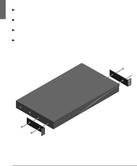
3.1.3.1 Installing the rack mount brackets
Line up the holes in the “long side” of the kit’s side brackets with the screw holes in the switch.
With a Phillips screwdriver, fasten the mounting brackets to the switch using two 8/32” x 1/2” pan head screws on each side.
Attach the four cage nuts or clip nuts to the rack mounting flange of the rack cabinet so that the nut is positioned on the inside of the rack.
Mount the switch assembly to the rack cabinet by matching the holes in the “short side” of each bracket to an appropriate set of matching holes on your rack cabinet. Next, insert the combination hex head screws through the slots in the bracket and the holes in the mounting rail, then into the cage nuts or clip nuts.
Figure 1: KVM s2-1611 Horizontal Installation
590-332-501E

KVM series2-1611 |
KVM s2-1611 hardware |
|
|
3.2KVM series2-1611 hardware
The following table lists the port and connection information for your appliance.
Server Ports |
|
|
|
Number |
16 |
|
|
|
|
|
|
|
|
|
|
Types |
PS/2, Sun and USB KVM s2-Adapters |
|
|
Connectors |
RJ45 |
|
|
Sync Types |
Separate horizontal and vertical |
|
|
Plug and Play |
DDC2B |
|
|
Video Resolution |
Analog Port Maximum: 1600 x 1280 @ 75 Hz |
|
|
|
Digital Port Maximum 1280 x 1024 @ 75 Hz |
|
|
Configuration Port |
|
|
|
Number |
1 |
|
|
Type |
Serial RS232 with terminal set to 9600 baud, 8 |
|
|
|
bits, 1 stop bit, no parity and no flow control |
|
|
Connector |
DB9 Male |
|
|
Network Connection |
|
|
|
Number |
1 |
|
|
Type |
Ethernet: IEEE 802.3, 10BaseT, |
|
|
|
Fast Ethernet: IEEE 802.3U, 100BaseT |
|
|
Connector |
RJ45 |
|
|
Analog Port |
|
|
|
Number |
1 |
|
|
Type |
PS/2 and VGA |
|
|
Connectors |
PS/2 MiniDIN and 15-pin D |
|
|
Table 1: KVM s2-1611 Ports and Connections
590-332-501E |
7 |

Power, Dimensions and Standards KVM series2-1611
3.2.1 Power ratings
|
|
Heat Dissipation |
92 BTU/Hr |
|
|
Airflow |
8 cfm |
|
|
Power Consumption |
25 W |
|
|
AC-input power |
40 W maximum |
|
|||
|
|
AC-input voltage rating |
100 to 240 VAC Autosensing |
|
|
AC-input voltage rating |
100 to 240 VAC Autosensing |
|
|
AC-input current rating |
1A |
|
|
AC-input cable |
18 AWG three-wire cable, with a three-lead |
|
|
|
IEC-320 receptacle on the power supply end |
|
|
|
and a country or region dependent plug on the |
|
|
|
power resource end |
|
|
AC-frequency |
50/60 Hz |
Table 2: KVM s2-1611 Power Ratings
3.2.2 Dimensions and environmental conditions
Dimensions |
|
(H x W x D) |
4.45 x 43.18 x 27.94 cm 1U form factor |
|
(1.75 x 17.00 x 11.00 in) |
Weight |
3.6 kg (8 lb) without cables |
Environmental |
|
Temperature |
10º to 50º Celsius( 50º to 122º Fahrenheit) |
|
operating |
|
-20º to 60º Celsius (-4º to 140º Fahrenheit) |
|
nonoperating |
Humidity |
20 to 80% noncondensing operating |
|
5 to 95% noncondensing nonoperating |
Table 3: KVM s2-1611 Dimensions and Environmental Information |
|
3.2.3 Standards |
|
|
|
Agency Approvals |
EN55022 Class A, EN55024, EN61000-3-3, |
|
FCC15 Class A, VCCI Class A, |
|
IEC950, EN60950, UL 1950/60950 third edition, |
|
CSA C22.2 No. 950 |
Table 4: KVM s2-1611 Standard Information
590-332-501E
KVM series2-1611 |
Installing the KVM s2-1611 |
|
|
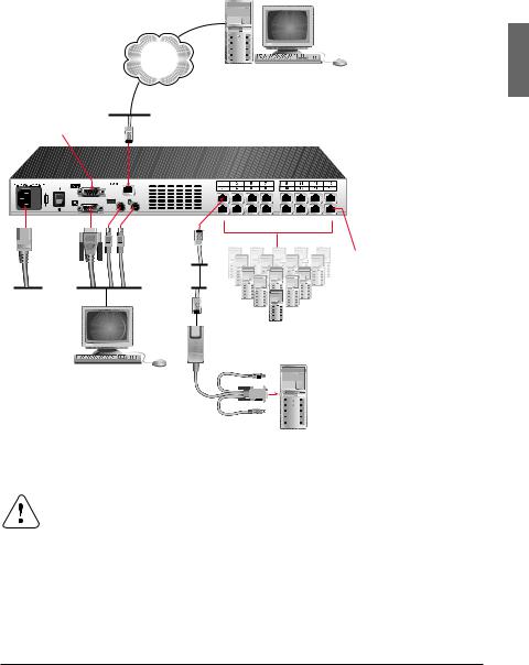
3.3Installing the KVM series2-1611
Figure 2 illustrates one possible configuration for your KVM s2-1611 appliance.
Follow the detailed set of procedures following Figure 2 to successfully install your appliance.
Network
Digital User
Configuration Port
for updating firmware
KVM s2-1611 Appliance
RI |
Port |
Power Cord
Servers 2-16
Local Analog
User
KVM s2-Adapter
PS/2, USB and
Sun cables are
available
Server 1
Figure 2: Basic KVM s2-1611 Configuration
Reducing the risk of electric shock or damage to your equipment
•Do not disable the power cord grounding plug. The grounding plug is an important safety feature.
•Plug the power cord into a grounded (earthed) outlet that is easily accessible at all times.
•Disconnect the power from the unit by unplugging the power cord from either the electrical outlet or the unit.
590-332-501E |
9 |
Installing/Configuring the KVM s2-1611 |
KVM series2-1611 |
|
|
3.3.1 Installing the KVM series2-1611 hardware
Connect a terminal or PC running terminal emulation software (such as
HyperTerminal) to the configuration port on the back panel of the appliance using a RS232 DB9 null modem cable. The terminal should be set to 9600 baud, 8 bits, 1 stop bit, no parity and no flow control.
Plug the supplied power cord into the back of the appliance and then into an appropriate power source.
When you turn on the power, the Power indicator on the front of the unit will blink for 30 seconds while performing a self-test. Approximately 10 seconds after it stops blinking, press the Enter key to access the main menu.
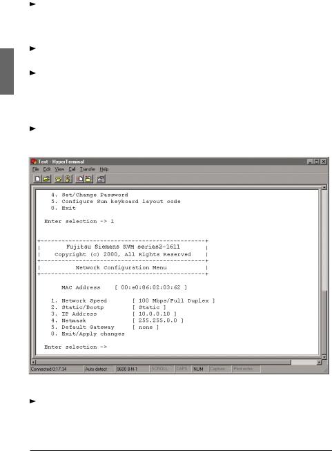
3.3.2 Configuring the KVM series2-1611 hardware
You will see the Terminal Applications menu with six options. Select option 1,
Network Configuration.
Figure 3: Network Configuration Menu
Select option 1 to set your network speed. When possible, you should set your connection manually without relying on the auto negotiate feature. Once
10 |
590-332-501E |
 Loading...