


Copyright
Fujitsu PC Corporation has made every eVort to ensure the accuracy and completeness of this document. However, as ongoing development eVorts are continually improving the capabilities of our products, we cannot guarantee the accuracy of the contents of this document. We disclaim liability for errors, omissions, or future changes.
LifeBook, Fujitsu,and the Fujitsu logo are trademarks of Fujitsu Limited.
The following are registered trademarks of IBM Corporation:IBM,IBM PC AT, IBM PS/2.
The following are registered trademarks of Microsoft Corporation:MS,MS-DOS, Windows NT, Microsoft Windows for Workgroups, Windows 95.
PCMCIA is a trademark of the Personal Computer Memory Card International Association.
Phoenix and the Phoenix logo are registered trademarks of Phoenix Technologies,Ltd. Pentium and MMX technology are trademarks of Intel Corporation.
All Kensington Corporation products are registered trademarks of Kensington Microware Limited.
PC-Doctor is a trademark of watergate.software.inc. SoftPEG™ is a registered trademark of CompuCore Multimedia Inc.
LapLink is registered trademark of Traveling Software Inc.
All other products are trademarks or registered trademarks of their respective companies.
We cannot guarantee the accuracy of the contents of this document. We disclaim liability for errors, omissions, or future changes.
© Copyright 1996 Fujitsu PC Corporation. All rights reserved. No part of this publication may be copied, reproduced, or translated, without prior written consent of Fujitsu PC Corporation. No part of this publication may be stored or transmitted in any electronic form without the written consent of
Fujitsu PC Corporation.
C A U T I O N
Changes or modification not expressly approved by Fujitsu PC Corporation could void this user’s authority to operate the equipment.
FCC Notices
Notice to Users of Radios and Television
These limits are designed to provide reasonable protection against harmful interference in a residential installation. This equipment generates,uses, and can radiate radio frequency energy and, if not installed and used in accordance with the instructions,may cause harmful interference to radio communications. However, there is no guarantee that interference will not occur in a particular installation. If this equipment does cause harmful interference to radio or television reception, which can be determined by turning the equipment oV and on, the user is encouraged to try to correct the interference by one or more of the following measures:
■Reorient or relocate the receiving antenna.
■Increase the separation between the equipment and receiver.
■Connect the equipment into an outlet that is on a diVerent circuit than the receiver.
■Consult the dealer or an experienced radio/TV technician for help.
Shielded interconnect cables must be employed with this equipment to ensure compliance with the pertinent RF emission limits governing this device.
If you experience trouble with this equipment please contact your support representative, toll free at 1-800- 8FUJITSU (1-800-838-5487) or Fujitsu Computer Products of America (FCPA),7300 NE Evergreen Parkway, Hillsboro, OR 97124, telephone 503-681-7300.
DOC (Industry Canada) Notices
Notice to Users of Radios and Television
This Class B digital apparatus meets all requirements of the Canadian Interference-Causing Equipment Regulations.
CET appareil numérique de la class B respecte toutes les exigence du Réglement sur le matérial brouilleur du Canada.
UL Notice(For Authorized Repair Technicians Only)
CAUTION: For continued protection against risk of fire, replace only with the same type and rating fuse.
CAUTION:Danger of explosion if CMOS battery is incorrectly replaced. Replace only with the same or equivalent type recommended by the manufacturer. Dispose of used batteries according to the manufacturer’s instruction.
WARNING: CMOS Battery may explode if mistreated. Do not recharge, disassemble or dispose of in fire.

T a b l e o f C o n t e n t s

T a b l e o f C o n t e n t s
Preface . . . . . . . . . . . . . . . . . . . vi
Section One
Setting Up Your LifeBook 400 Series
Unpacking. . . . . . . . . . . . . . . . . . |
. . 2 |
Overview of Features . . . . . . . . . . . . . |
. 3 |
Component Identification . . . . . . . . . . |
. 4 |
Power Sources. . . . . . . . . . . . . . . . . |
. 9 |
Data Security . . . . . . . . . . . . . . . . . |
. 9 |
Starting Your NoteBook for the First Time |
. 10 |
User Registration . . . . . . . . . . . . . . |
. 13 |
Learning About Your Operating System |
|
and Application Software. . . . . . . . . . |
14 |
Section Two
Using Your LifeBook 400 Series
Using your LifeBook 400 Series
from Fujitsu . . . . . . . . . . . . . . . . . 16 Status Indicator Panel . . . . . . . . . . . . . 17 Power Management Controls . . . . . . . . . 20 Power On . . . . . . . . . . . . . . . . . . . 22 Special Operating System Features . . . . . . 23 Power OV . . . . . . . . . . . . . . . . . . . 23 Restarting the System . . . . . . . . . . . . . 24 Battery . . . . . . . . . . . . . . . . . . . . . 25 Integrated TouchPad Pointing Device . . . . 28 Using the Keyboard . . . . . . . . . . . . . . 30 Floppy Disk Drive . . . . . . . . . . . . . . . 32 CD-ROM Drive . . . . . . . . . . . . . . . . 35 Hard Drive . . . . . . . . . . . . . . . . . . . 35 Power-Saving . . . . . . . . . . . . . . . . . 36 Video and Audio Functions. . . . . . . . . . 41 File Transfers. . . . . . . . . . . . . . . . . . 43
Infrared Communication Port . . . . . . . . 43 Anti-Virus Software . . . . . . . . . . . . . . 43
Section Three
Configuring Your LifeBook 400 Series
Boot Sequence . . . . . . . . . . . . . . . . . 46
Identifying the Drives . . . . . . . . . . . . . 46 BIOS Setup Utility. . . . . . . . . . . . . . . 47 Navigating Through the Setup Utility . . . . 48 Main Menu – Setting System Parameters . . 50 Exiting from the Main Menu . . . . . . . . . 59 Advanced Menu – Setting Device Controls . 59 Exiting from the Advanced Menu . . . . . . 66 Security Menu . . . . . . . . . . . . . . . . . 67 Exiting from the Security Menu . . . . . . . 69 Power Savings Menu . . . . . . . . . . . . . 71 Exiting from the Power Savings Menu . . . . 71 Boot Menu – Selecting the
Operating System Source. . . . . . . . . . 73 Exiting from the Boot Menu . . . . . . . . . 74 Exit Menu – Leaving the Setup Utility . . . . 74 Setting Up Your Save-To-Disk
File Allocation. . . . . . . . . . . . . . . . 75
ii

Section Four |
|
User Installable Features |
|
RAM Module . . . . . . . . . . . . . . . . . |
78 |
PC Cards . . . . . . . . . . . . . . . . . . . . |
81 |
Installing a Theft Prevention Lock . . . . . . |
84 |
Optional External Installation of |
|
Floppy Disk Drive . . . . . . . . . . . . . |
84 |
Nickel Metal Hydride Battery Pack . . . . . . |
85 |
Multi-function Bay . . . . . . . . . . . . . . |
86 |
CD-ROM Drive . . . . . . . . . . . . . . . . |
87 |
Removable Floppy Disk Drive . . . . . . . . |
88 |
Installing Devices on the LPT Port . . . . . . |
88 |
Installing Devices on the COM Port . . . . . |
88 |
Installing External Monitors . . . . . . . . . |
88 |
Installing a Mouse or Keyboard . . . . . . . |
88 |
Installing a Replicator Port or |
|
Mini-Docking Station . . . . . . . . . . . |
88 |
Installing Audio Input Devices . . . . . . . . |
89 |
Installing Audio Output Devices . . . . . . . |
89 |
L i f e B o o k 4 0 0 S e r i e s f r o m F u j i t s u
T a b l e o f C o n t e n t s
Section Five
Troubleshooting
Identifying the Problem . . . . . . . . . . . . 92
Specific Problems . . . . . . . . . . . . . . . 93 Power On Self Test Messages . . . . . . . . 112 Emergency CD-ROM Tray Release . . . . . 115 Installing and Removing the
Internal Hard Drive . . . . . . . . . . . . 115 Restoring Your Pre-installed Software
from CD-ROM . . . . . . . . . . . . . . 116
Section Six
Care and Maintenance
Care and Maintenance . . . . . . . . . . . . 119 Caring for Your Notebook . . . . . . . . . . 119 Increasing Battery Life . . . . . . . . . . . . 119
Appendices
Appendix A Specifications . . . . . . . . . . 122 Warranty . . . . . . . . . . . . . . . . . . . 122
LifeBook 435Dx Specifications . . . . . . . 122 Approvals . . . . . . . . . . . . . . . . . . . 124 Popular Accessories . . . . . . . . . . . . . 124 Appendix B Glossary. . . . . . . . . . . . . 126
Index . . . . . . . . . . . . . . . . . . . . 134
iii

P r e f a c e
L i f e B o o k 4 0 0 S e ri e s f r o m F u j i t su

P r e f a c e
Preface
The LifeBook 400 Series from Fujitsu PC Corporation is a powerful notebook computer. It is powered by an Intel Pentium microprocessor with MMX technology, has a built-in color display, a CD-ROM drive and brings the computing power of desktop personal computers (PCs) to a portable environment.
This manual explains how to operate your LifeBook 400 Series’ hardware and built-in system software. The LifeBook 400 Series is compatible with the IBM PC AT.® Depending on your model,it comes with Windows® 95, Windows for Workgroups™ Version 3.11 and MS-DOS Version 6.22 or only Windows 95 pre-installed. When you first start your notebook, you will be asked to select a single operating system if both are present.
(See pages 10–13 for more information on selecting your operating system.)
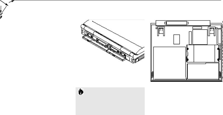
Your LifeBook 400 Series is a completely selfcontained unit with a passive-matrix (DSTN) color LCD display. It has a powerful interface that enables it to support a variety of optional features. (Figure P-1.)
C A U T I O N
When you first turn on your LifeBook 400 Series the Windows 95 Setup screen will appear. This is true even if you will be using Windows for Workgroups.
vi

L i f e B o o k 4 0 0 S e r i e s f r o m F u j i t s u
L i f e B o o k 4 0 0 S e r i e s f r o m F u j i t s u
Figure P-1 LifeBook 400 Series
with both Fujitsu and
Third Party Options
vii

P r e f a c e
Conventions Used in the Guide
In this manual, figures which show screens are intended as examples only, and screen and file names may diVer in actual use.
Messages displayed by your LifeBook 400 Series appear in Courier type.
Example: Starting MS-DOS
Commands that you enter into your notebook using the keyboard appear in Courier type. Example: C:>DIR/P
Keyboard keys are shown in boldface Helvetica type.
Example: Fn, F1, Esc, and Ctrl.
Pages with additional information about a specific topic are cross-referenced within the text. Example: (See page xx.)
P O I N T |
|
C A U T I O N |
The point icon highlights information |
|
The caution icon highlights information |
that will enhance your understanding of |
|
that is important to your safety, to the |
the subject material. |
|
safe operation of your notebook, or to |
|
|
the integrity of your files. Please read all |
|
||
|
|
caution information carefully. |
|
|
|
viii

S e c t i o n O n e
Setting Up Your LifeBook 400 Series
Unpacking . . . . . . . . . . . . . . . . . . . 2
Overview of Features . . . . . . . . . . . . . 3
Component Identification . . . . . . . . . . . 4
Power Sources . . . . . . . . . . . . . . . . . 9
Data Security. . . . . . . . . . . . . . . . . . 9
Starting Your Notebook for the First Time . . 10
User Registration . . . . . . . . . . . . . . . 13
Learning About Your Operating System
and Application Software . . . . . . . . . . . 14
S e c t i o n O n e
Section ONE
Setting Up Your LifeBook 400 Series from Fujitsu
This section describes how to set up your LifeBook 400 Series from Fujitsu. We strongly recommend that you read it before using your notebook – even if you are already familiar with notebook computers.
Unpacking
When you receive your notebook,unpack it carefully, and compare the parts you have received with the items listed below.
For a standard configuration you should have:
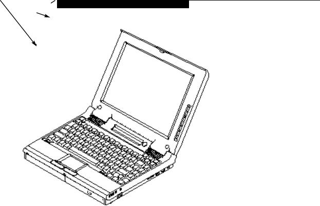
■LifeBook 400 Series from Fujitsu.(Figure 1-1.)
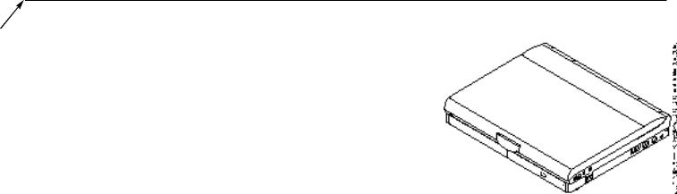
■AC Adapter with AC power cord (located in the accessories box).(Figure 1-2.)
■Modular 10-speed CD-ROM Drive (already installed in your notebook).
■Modular 3.5" Floppy Disk Drive (located in the accessories box).(Figure 1-3.)
■User’s Guide.
■Registration card and customer information pack.
■Microsoft Windows 95 Manual.
■Additional equipment and documentation depending on the option package you have purchased.
Figure 1-1 LifeBook 400 Series Notebook
Figure 1-2 AC Adapter Unit
Figure 1-3 Floppy Disk Drive
2

Once you have checked and confirmed that your notebook system is complete, connect the AC Adapter and follow the instructions on pages 10–13 to accept the conditions for using the LifeBook 400 Series and for selecting the operating system you will use. When you have completed that setup process please complete and send in your registration card.
Overview of LifeBook 400 Series Features
The LifeBook 400 Series is a compact, yet powerful notebook computer available with standard features including:
(See Appendix A, pages 122–125, for detailed information.)
■133 MHz Intel Pentium™ processor with MMX technology.
■16MB EDO RAM standard, expandable to 80MB.
■12.1" passive-matrix (DSTN) color display with 800 x 600 resolution.
■1MB Video RAM.
S e t t i n g U p Y o u r L i f e B o o k 4 0 0 S e r i e s
■Built-in 1.3GB hard drive.
■Multi-function bay which supports warm swapping of the following:
■3.5" floppy disk drive (included with all models).
■10-speed CD-ROM drive (included with all models).
■Nickel Metal Hydride (NiMH) Battery Pack.
■16-bit Sound Blaster™-compatible sound chip.
■Zoomed Video port for full motion video acceleration.
■Built-in stereo speakers.
■Two Type II or one Type III PC Card slot.
■IrDA 1.0 compatible infrared port for wireless data transfer.
■Integrated TouchPad Pointing Device for easy cursor control.
■External monitor support.
L i f e B o o k 4 0 0 S e r i e s f r o m F u j i t s u
■Full size keyboard with three dedicated Windows 95 keys.
■Hot swap connection for an external keyboard or an external mouse.
■Stereo line in jack.
■Stereo headphone jack.
■Standard Pre-installed software:
■Operating System.
■LapLink®7.0 for file transfers via modem, cable or infrared port.
■PC-Doctor™ for system diagnostics.
■SoftPEG™ from CompCore,a MPEG-1 video player.
■ESS AudioRack™, to take advantage of the notebook’s audio capabilities.
■McAfee® VirusScan®.
■Some models may include additional software.
3
S e c t i o n O n e
Component Identification
For detailed specifications refer to Appendix A on pages 122–125.
Display Panel Latch
This latch locks and releases the display panel.
LCD Display Panel
This is a color LCD panel with back lighting for the display of text and graphics.
Brightness Control
The brightness control adjusts the overall intensity of the display screen back lighting.
Contrast Control
The contrast control adjusts the contrast of the display screen. It is located just below the brightness control.
Status Indicator Display
LCD display of the status of the power state and source, Suspend Mode, battery charge, floppy disk drive activity, hard drive activity, CD-ROM drive activity, PC Card activity, Caps Lock, Num Lock and Scroll Lock.
Suspend/Resume Button
The Suspend/Resume Button allows you to suspend computer activity without turning oV your notebook power, and to return it to an active state. This feature saves power, and is particularly useful when your notebook is running only on battery power. (See pages 20–22, 36–41,and 69–72 for more information on Power Management.)
Display Latch
Figure 1-4 Top and Front Panel
4
L i f e B o o k 4 0 0 S e r i e s f r o m F u j i t s u
S e t t i n g U p Y o u r L i f e B o o k 4 0 0 S e r i e s
Display Latch
LCD Display
Status Indicator Display
Stereo Speaker
Brightness Control
Keyboard
 Contrast Control
Keyboard Removal Tab
Suspend/Resume Button
Closed Cover Switch
Stereo Speaker
TouchPad Pointing Device
Multi-function Bay |
Keyboard Removal Tab |
|
Figure 1-5 LifeBook 400 Series with Display Open |
5
S e c t i o n O n e
C A U T I O N
Be sure you know what settings are active for your Suspend/Resume Button before you use it as misuse can result in data loss. (See the Power Savings Menu of the BIOS Setup Utility on pages 69–72 for more information.)
Closed Cover Switch
This switch turns oV the LCD back lighting when the display panel is closed,thus saving power.
Speakers
The built-in dual speakers output stereo sound from your notebook.
Keyboard
A full size keyboard with dedicated Windows 95 keys for input into your notebook.
Keyboard Removal Tabs
A pair of tabs which cover screws which hold
the front of the keyboard in place.Lifting the tabs is only necessary to access the Memory Expansion Chamber which is under the keyboard. (See pages 78–81 for more information. )
C A U T I O N
Do not attempt to install or remove a RAM Module if your notebook has been recently used. The surface area under the keyboard can be very hot and may injure you.
TouchPad Pointing Device
A touch sensitive cursor control system with two click buttons.
Multi-function Bay
This bay accommodates:
■10-speed CD-ROM drive.
■3.5" floppy disk drive.
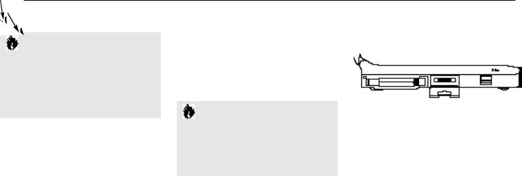
PC Card |
Eject |
Optional External |
Built in |
Slots |
Buttons |
Floppy Disk Drive |
Microphone |
|
|
Adapter Connector |
|
Lock |
Battery Eject Button |
Figure 1-6 LifeBook 400 Series Left Side Panel
PC Card Slots, with Cover,
Lock and Eject Button
The PC Card Slots allow you to install two type I or II PC Cards or one type III PC Card. (See pages 81–83 for more information on PC Cards.) The buttons to the left of the card slots lock the cards in place,and the buttons to the right of the slot ejects the card(s) from the slot.
External Floppy Disk Drive Adapter Connector
A connector for attaching an optional external floppy disk drive adapter. The adapter allows you to use your modular floppy disk drive when the multi-function bay is being used for another purpose.
6
Main Battery Eject Button
This button releases the Removable Main Nickel Metal Hydride Battery Pack for removal and installation.
Built-in Microphone
The built-in microphone allows mono audio input to your notebook.
Volume Control
This knob provides hardware control of sound level of audio outputs from your notebook.
Audio Stereo Line In Jack
The Audio Input Jack allows you to connect an external audio source to your notebook,like an audio cassette player. This jack will not support an external microphone.
Headphone Jack
You can install headphones or powered external speakers in the Headphone Jack.
Multi-function Bay Release Button
This is the release to allow removal and installation of devices in the Multi-function Bay.
L i f e B o o k 4 0 0 S e r i e s f r o m F u j i t s u
S e t t i n g U p Y o u r L i f e B o o k 4 0 0 S e r i e s
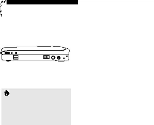
Power Switch |
PS/2 Connector |
This switch is the main power switch for |
The PS/2 Connector allows you to connect |
your notebook. |
an external PS/2 keyboard,mouse, or |
|
numeric keypad. |
Volume |
Headphone |
Power Switch DC Power |
Control |
Jack |
Input Connector |
Audio |
Multi-function Bay |
PS/2 |
Theft |
Stereo |
Prevention |
||
Line In |
Release Button |
Connector |
Lock Slot |
Jack |
|
|
|
Figure 1-7 LifeBook 400 Series Right Side Panel
DC Power Input Connector
The DC Power Input Connector allows you to plug in the Fujitsu AC Adapter or the optional Fujitsu Auto Adapter.
Theft Prevention Lock Slot
This is a slot that allows you to attach a physical lock down device.
Serial Interface Connector (COM Port)
The Serial Interface Connector allows you to connect serial RS-232C devices, such as a serial printer or a serial scanner.
C A U T I O N
There are software volume controls. The knob setting and the software settings will interact. Software volume Off will override the knob setting. (See Volume Control on pages 42–43 for more information.)
Expansion Bus Connector
This connector is for connection to an optional port replicator or docking station. The connector cover must be closed and the sliding panel opened to reveal only the Expansion Bus Connector when connecting a port replicator or docking station.
7
S e c t i o n O n e
Parallel Interface Connector (LPT Port)
The Parallel Interface Connector allows you to connect parallel devices, such as a parallel printer, to your notebook.
External SVGA or Hi Res Monitor Connector
This connector allows you to connect an external VGA or SVGA CRT or Hi-Res monitor to your notebook.
Infrared IrDA Compatible Communication Port
The IrDA compatible Communication Port allows you to communicate with another IrDA compatible device without a cable. (See page 43 for more information.)
Tilt Adjustment Feet
These are a pair of feet which flip down and hold the back of the keyboard approximately 6° higher than the front when resting on a flat surface. They are designed to make using your notebook keyboard more comfortable.
Main Unit Label
This label has the model number, serial number and other information about your notebook.
COM Port
Expansion Bus Connector
LPT Port
Monitor Connector
Infrared Port
Figure 1-8 LifeBook 400 Series Back
C A U T I O N
The cover which closes over the connectors on the rear of your notebook can be damaged if it is left open when your notebook is moved around.
Tilt Adjustment Foot |
Tilt Adjustment Foot |
Configuration
Label
Main
Unit
Label
Internal
Hard Drive
Chamber
Multi-function Bay
Battery Chamber
Figure 1-9 LifeBook 400 Series Bottom
Configuration Label
This label has manufacturer information that you will need to give your support representative so that he or she can help you. It identifies exactly the version of various component parts of your notebook.
8

Internal Hard Drive Chamber
This chamber houses the internal hard drive. It should only be accessed for maintenance by an authorized maintenance provider.
Battery Chamber
This chamber houses the Nickel Metal Hydride Battery Pack or the optional Lithium ion Battery Pack.
C A U T I O N
The Nickel Metal Hydride Battery Pack is not charged when you purchase your notebook. Initially you will need to connect the AC Adapter or the Auto Adapter to use it. It can take up to 3 hours to charge a Battery Pack if your notebook is Off or in Suspend Mode. If your notebook is in use, it can take up to 9 hours or more to charge a Battery Pack.
L i f e B o o k 4 0 0 S e r i e s f r o m F u j i t s u
S e t t i n g U p Y o u r L i f e B o o k 4 0 0 S e r i e s
Power Sources
Your notebook has three possible power sources: the Nickel Metal Hydride Battery Pack, the AC Adapter, or the optional Auto Adapter.
Connecting the Power Adapters
The AC Adapter or the Auto Adapter provides power for operating your notebook and charging the battery pack.(Figure 1-10.)
To Connect the AC Adapter
1.Plug the DC output cable of the AC Adapter into the DC Power Input Connector on the right side panel of your notebook.
2.Plug the AC Adapter into an AC electrical outlet.
To Connect the Optional Auto Adapter
1.Plug the DC output cable into the DC Power Input Connector on the right side panel of your notebook.
2.Plug the Auto Connector into the cigarette lighter of a car or other vehicle with the ignition key in the On or the Accessories position.
Data Security
Your LifeBook 400 Series from Fujitsu has a built-in hardware control password security feature that allows you to protect stored data from unauthorized access. Your operating system and some applications have software control password security features that allows you to protect all or portions of the data stored in your notebook from unauthorized access.
Hardware Data Security Features
When you are using the built-in hardware control password to gain access to your notebook the actual password will not appear on the screen. This is a safety precaution. The hardware control security parameters are set from the BIOS Setup Utility. (See Security Menu on pages 67–69 for more information on setting and clearing passwords and enabling and disabling built-in security features.)
9

S e c t i o n O n e
Software Data Security Features
The operating system and some applications have security features that are independent of the built-in hardware protection features that are controlled from the BIOS. See your software documentation for more information about these features.
C A U T I O N
Make sure you memorize your passwords for both hardware and software. If you forget, you may not be able to use your notebook, and you will have to contact your service provider and arrange to have them reset the hardware system password. See your software manuals for what to do if you forget your software security password(s).
C A U T I O N
Software security feature passwords may not be the same as the hardware security passwords. Be sure you know which features are controlled from software and which from hardware or you may lock yourself out of your own data or lock
up your hardware and not be able to operate your notebook.
Starting Your Notebook for the First Time
Booting the System
The first time that you turn on your notebook you will need to attach your AC Adapter as the battery is not charged when it arrives. We strongly recommend that you do not attach any other external devices and do not put any CD or floppy disk in the drives until you have gone through the initial power on sequence.
When you turn on your notebook for the first time it will p erform a power on self test and display some status information on the screen with a message:
Press <F2> for Setup.
If you do nothing the system will read the hard drive for the operating system software and the Windows 95 Setup Screen will appear.
(See Power On on pages 22–23 for additional help.) You will then be stepped through the condition of useand operating system selection process. You must complete this initial process before you will be able to use your notebook.
C A U T I O N
If you have purchased a system which allows you to use a choice of operating systems, the Operating System selection can only be made once. You cannot change your mind, the option will never be available again.
10

Conditions of Use
The first time you start your notebook you must confirm your acceptance of the copyright limitations for your pre-installed software. If you have purchased a unit which allows you to
use a choice of operating systems you must choose between Windows 95 and Windows for Workgroups. Once you have chosen your operating system you cannot change your mind, the other system will not be available to you.Please decide carefully. After your notebook completes the installation of the operating system it will not ask you again for confirmation of the conditions of use nor to choose an operating system.
C A U T I O N
When you first turn on your notebook the Windows 95 Setup screen will appear. This is true even if you will be using Windows for Workgroups.
S e t t i n g U p Y o u r L i f e B o o k 4 0 0 S e r i e s
Every LifeBook 400 Series Model has 10 screens to read carefully and/or answer questions by typing in information. If your notebook has a choice to use Windows for Workgroups there will be three additional screens. All of the screens are Windows 95 Setup screens.
You cannot use your notebook until this setup process is completed. The bottom of each screen has a <Back Button, a Next> Button and a Cancel Button which are activated by the Integrated Touchpad Pointing Device cursor control and button click. The <Back Button will return you to the previous screen. The Next> Button activates any choices or information you have entered and takes you on to the next screen. The Cancel Button allows you to stop the setup process. If you stop the process your notebook will come back to the place in the Windows 95 Setup where you left oV the next time you start your machine. The screens you will be required to respond to are shown with the required action.
L i f e B o o k 4 0 0 S e r i e s f r o m F u j i t s u
Welcome to Windows Setup
Read and then click on the Next> Button.
Regional Settings
Select language, number format,date format, etc. for the operating system to use by moving cursor up and down the list to the desired world region shown in the table and then click on the Next> Button. Use the up arrow ’ and down arrow ‘ keys to move down up and down the text one line at a time.
Keyboard Layout
Select the keyboard language and format you wish to use by moving cursor up and down the list to the desired selection shown in the table and then click on the Next> Button. You can scroll through the text using the up arrow ’ and down arrow ‘ keys to move down up and down the text one line at a time.
User Information – Software Licensing
Fill in your name and your company name as you would like to see it on the software license and then click on the Next> Button. You must make an entry in order to continue.
11
S e c t i o n O n e
P O I N T
If your system comes with Windows 95 only, you will find a Recovery CD-ROM packet in your accessories box. Please store the packet in a safe place in case there is a loss of data. (See Restoring Your Pre-installed Software from CDROM on page 116.)
License of Windows 95
Read carefully and then click on the Next> Button.
License Agreement
Read the agreement carefully. You can scroll through the text using the Integrated TouchPad Pointing Device to activate the scroll bar or use the up arrow ’ and down arrow ‘ keys to move up and down the text one line at a time. When you finish reading simply point and click to accept or reject the terms of the agreement and then click on the Next> Button.
P O I N T
If you reject the terms of the license agreement the operating system setup will abort and shutdown your notebook. When you turn on the system the next time, it will begin the Setup process again.
Certificate of Authenticity
Look in the box that your notebook came in and you will find a Windows 95 Certificate of Authenticity and a Windows 95 Users manual. On the certificate – and also on the back of the manual – you will find a bar-code with a number above it. These numbers should be the same. They are your product code and the number you should enter on the Certificate of Authenticity screen. When you have entered the number exactly as shown then click on the Next> Button.
C A U T I O N
If your system came with a choice of operating systems, you will need to make back up disks. (See Create System Disks page 13.)
*Windows Version
To select Windows for Workgroups point and click on the Change Button. To select Windows 95 point and click on the Next> Button.
(If you select Windows 95 you will go directly to the Configuring the Computer Screen.)
*Operating System Choice
To select Windows for Workgroups point and click on the Windows for Workgroups selection and then point and click on the Next> Button. To select Windows 95 point and click on the Windows 95 selection and then point and click on the Next> Button.
Configuring the Computer
If you have a unit with only Windows 95 or have selected Windows 95 this screen will appear when Windows 95 is ready to install. (If you purchased a LifeBook 400 Series which only comes with Windows 95 this screen will appear immediately after the Certificate of Authenticity Screen.) You may be prompted for
time zone and printer. You do not need to select a printer at this time.
12

Installing Devices
This screen will appear while your notebook loads the operating system and when it finishes it will automatically go to the next screen.
C A U T I O N
If you have chosen Windows for Workgroups please follow the instructions on the coupon that is included in the accessories box with your notebook. This provides for exchanging the Windows 95 manual for a Windows
for Workgroups manual.
*Create System Disks
If your system came with a choice of operating systems, you will be prompted to create system disks. We strongly recommend that you make a system backup so you can restore your factory installed software in case of data loss. If you
S e t t i n g U p Y o u r L i f e B o o k 4 0 0 S e r i e s
have chosen Windows 95 you will need to backup your operating system and your factory installed applications and drivers. The backup will require 40 floppy disks. If you have chosen
Windows for Workgroups you only need to backup the factory installed applications and drivers. The backup will require 9 floppy disks.
Finishing Setup
Click on the Finish Button and your notebook will restart with the selected Windows operating system ready for normal operation.
P O I N T
If you do not have enough floppy disks available during the setup process you can create system backup disks at any time. From the Start Menu, select Accessories, then System Tools, then Create System Disks.
L i f e B o o k 4 0 0 S e r i e s f r o m F u j i t s u
User Registration
There are three ways to register your notebook.
1.Mail-in Registration – Fill in the registration card provided in the box with your LifeBook
400 Series and mail it to Fujitsu.
2.On-line Electronic Registration – Fill out the registration form behind the Fujitsu Icon on your Desktop and send it by e-mail.
3.Internet Registration – Use the registration utility on the Fujitsu PC S ervice and Support Web Site at www.8fujitsu.com to register your notebook.
13

S e c t i o n O n e
Learning About Your Operating System
and Application Software
Tutorials
All operating systems and most application software have built-in tutorials. We highly recommend that you step through the tutorial before you use an application, even if you
are familiar with the same application on a diVerent machine,an earlier version of the application, or with a similar p roduct.
Manuals
In the accessories box you will find manuals f or Windows 95 and other pre-installed software. If you have Windows for Workgroups,and have chosen it as your operating system, follow the instructions on the coupon in the accessories box in order to exchange the Windows 95 manual for a Windows for Workgroups manual. Software manuals of pre-installed software that
are not in the accessories box are available online. See the help screens of your pre-installed software. We recommend that you review these manuals for general information on the use of these applications and to get a basic understanding of what is covered in the manual,and how it is organized,should questions arise as you use the applications.
14

S e c t i o n T w o
Using Your LifeBook 400 Series from Fujitsu
Using Your LifeBook 400 Series from Fujitsu |
. |
16 |
|||
Status Indicator Panel. . . . . . . . |
. . . . . 17 |
||||
Power Management Controls. . . . |
. . . . . 20 |
||||
Power On . . . . . . . . . . . . . |
. . . . . 22 |
||||
Special Operating System Features . |
. . . . . 23 |
||||
Power Off . . . . . . . . . . . . . |
. |
. . |
. |
. |
23 |
Restarting the System . . . . . . . |
. |
. . |
. |
. |
24 |
Battery . . . . . . . . . . . . . . . |
. |
. . |
. |
. |
25 |
Integrated TouchPad Pointing Device. |
. . |
. |
. |
28 |
|
Using the Keyboard. . . . . . . . . . |
. . |
. |
. |
30 |
|
Floppy Disk Drive . . . . . . . . . . |
. |
. . |
. |
. |
32 |
CD-ROM Drive . . . . . . . . . . . |
. |
. . |
. |
. |
35 |
Hard Drive . . . . . . . . . . . . . |
. |
. . |
. |
. |
35 |
Power-Saving. . . . . . . . . . . . |
. |
. . |
. |
. |
36 |
Video and Audio Functions . . . . . |
. |
. . |
. |
. |
41 |
File Transfers . . . . . . . . . . . . . . . . . 43
Infrared Communication Port . . . . . . . . . 43
Anti-Virus Software. . . . . . . . . . . . . . 43
S e c t i o n T w o
Section TWO
Using Your LifeBook 400 Series from Fujitsu
This section describes the indicators, buttons, connections and operating modes of your notebook and their use.
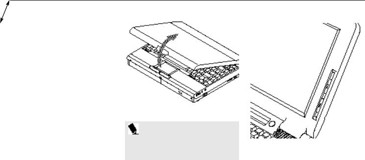
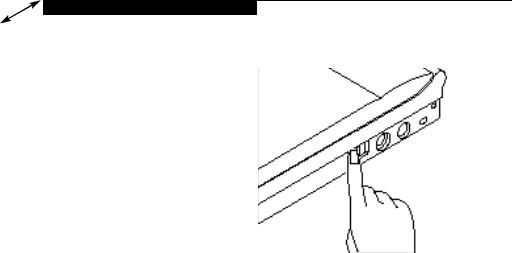
Opening the Unit
Lifting the latch releases the cover and allows your notebook to be opened.Lift the display backward until the screen is at a comfortable viewing angle.(Figure 2-1.)
Adjusting the Built-in Display
When you turn on your notebook, you may want to adjust the brightnesslevel of the screen for best visibility. To do this, adjust the brightness slider on the right side of the built-in display screen. You may need to adjust the brightness periodically for diVerent operating environments. You will probably want to adjust the contrast as well as the brightness. To do this, use the contrast slider on the right side of the built-in display screen just below the brightness control.(Figure 2-2.)
Figure 2-1 Opening the LCD Display
P O I N T
The higher the level of brightness, the more power your notebook will consume, and the faster the battery will discharge.
Adjusting the Keyboard Angle
On the bottom of your notebook, near the back,are a pair of feet which flip down and hold the back of the keyboard about 6° higher than the front when resting on a flat surfa ce.
Brighter
Less Bright
More Contrast
Less Contrast
Figure 2-2 Display Adjustments
They are designed to make using your notebook more comfortable when using the keyboard. The feet must be folded flat against the bottom of your notebook when opening or using a CD-ROM or it will not open or operate properly. (See Figure 1-9 on page 8. )
16
C A U T I O N
Do not operate the CD-ROM drive or attempt to open the tray unless your notebook is sitting on a flat surface and the adjustment feet are folded against the bottom of your notebook. Using a CDROM drive when it is not level may damage the drive or prevent proper operation.
C A U T I O N
When you are not using the adjustment feet be sure that they are folded flat against the bottom of your notebook. They could be broken off, or injure someone, if not used properly.
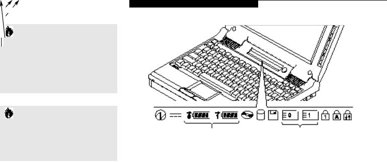
Status Indicator Panel
The Status Indicator LCD Display Panel is located in the recess just above the keyboard. (Figure 2-3.) The appropriate indicators become visible when you use your notebook.
L i f e B o o k 4 0 0 S e r i e s f r o m F u j i t s u
U s i n g Y o u r L i f e B o o k 4 0 0 S e r i e s
Power |
Battery |
Battery |
Unused CD-ROM |
Floppy |
|
NumLock |
Scroll Lock |
AC |
Charging |
Level |
Drive |
Disk |
PC Card Indicator |
Indicator |
|
Adapter |
Inidcator |
|
Access |
Drive |
Access |
CAP Lock |
|
|
|
|
Indicator |
Access |
Indicators |
||
|
|
|
Indicator |
||||
|
|
Battery |
Hard |
Indicator |
|||
|
|
|
|
||||
|
|
Identifier |
Drive |
|
PC Card |
|
|
|
|
|
Access |
|
Identifier |
|
|
|
|
|
Indicator |
|
|
|
|
Figure 2-3 Status Indicators
17
S e c t i o n T w o
Power Indicator
The Power Indicator tells you when the system is operational. It is on steady when there is power to your notebook, and blinks when the system is in Suspend Mode. It goes oV when the system has entered Save-to-Disk Mode, has entered the Windows 95 shutdown inactivity state, or the power is turned oV from the Power Switch.
P O I N T
When your notebook has been shutdown from Windows 95, it is the same as turned off from the Power Switch except that it can be turned on by pressing the Suspend/Resume Button. It is not drawing current in this state.
AC Adapter Indicator
The AC Adapter Indicator tells you whether the system is operating on the AC or Auto Adapter, or running on battery alone. The indicator is On
when either of the adapters is active and OV when power comes from the battery alone. If a battery is charging the power adapter is active regardless of the setting of the Power Switch.
The AC Adapter is also active in the Windows shutdown state, regardless of the battery status. If there is no battery charging, and the Power Switch is OV, then the AC Adapter Indicator and the Battery Condition Indicator will all be OV.
Battery Condition Indicator
This indicator shows whether or not the Nickel Metal Hydride Battery Pack is installed and indicates the condition.(Figure 2-3.) Battery 0 is the Nickel Metal Hydride Battery Pack. The Battery Status Indicator is displayed only if the battery is installed.(Battery 1 display will flash when you power up but will never be displayed.)
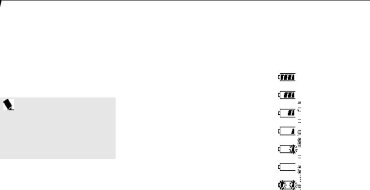
A small arrow icon appears to the left of the battery symbol and above the number if the battery is charging. The charging indicator flashes if the battery is too hot or too cold to charge. The charging indicator operates whether the Power Switch is OV or On. The symbols inside the bat-
tery outline indicate the operating level available for the battery. (Figure 2-4.) If there is no battery charging and the Power Switch is OV then the AC Adapter Indicator and the Battery
Condition Indicator will all be OV.
76–100%
51–75%
26–50%
13–25%
Low Battery ≤12%
Dead Battery
Shorted Battery
Figure 2-4 Battery Condition Indicator
18

C A U T I O N
Turning off the power with the Power Switch or using the Suspend/Resume Button when any of the Access Indicators are On may cause loss of data and/or system errors.
CD-ROM Drive Access Indicator
The CD-ROM Access Indicator tells you a CD-ROM is being accessed.
P O I N T
When using Windows 95, the CD-ROM automatic insertion function periodically checks for a CD installed in the drive, causing the access indicator to flash. The CD automatic insertion function allows the system to automatically start a CD application as soon as a CD is inserted in the drive and the tray is closed. It will begin playing an audio CD or will start an application if the CD has an auto run file on it.
L i f e B o o k 4 0 0 S e r i e s f r o m F u j i t s u
U s i n g Y o u r L i f e B o o k 4 0 0 S e r i e s
P O I N T
If you do not wish to have the CD automatic insertion function you can disable it.
7.Click on the + to the left of the CD-ROM icon. The manufacturer and model of the installed CD-ROM Drive will be displayed.
8.Click on the CD-ROM Drive manufacturer and model identification.
In order to disable the CD automatic insertion function proceed as follows:
1.Save all data and close all applications.
2.Click on the Start Button.
3.Point to Settings.
4.Click on the Control Panel. The Control Panel window will be displayed.
5.Double click on the System icon. The System Properties dialogue box will be displayed.
6.Click on the Device Manager tab. The device list will be displayed.
9.Click on Properties. The CD-ROM Drive Properties dialogue box will be displayed.
10.Click on the Settings tab.
11.Click on the automatic insertion box to toggle it OV.
12.Click on OK.
13.Click on OK in the System Properties dialogue box.
14.Restart your notebook according to the message displayed.
You can re-enable the function by repeating the process except in step 11 change the setting to On.
19

S e c t i o n T w o
C A U T I O N
If you switch off power using the Power Switch or operate the Suspend/Resume Button while any of the access indicators are on, you may cause data to be lost and/or a system error to occur.
Hard Drive Access Indicator
The Hard Drive Access Indicator tells you when the internal hard disk is being accessed.
Floppy Disk Drive Access Indicator
The Floppy Disk Drive Access Indicator tells you a floppy disk is being accessed.
PC Card Access Indicators
The PC Card Access Indicator tells you an installed PC Card is being accessed. Card 0 is the bottom connector and Card 1 is the upper connector in the card slot. Type III cards are always Card 0 only.
P O I N T
Windows 95 displays of PC Card slot numbers may be different than Status Indicator slot numbers.
NumLock Indicator
The NumLock Indicator tells you the internal keyboard is set in ten-key numeric mode. (See page 31 for more information on the numeric keypad.) You can activate the NumLock Mode by pressing the Scr Lk/Num Lk key while holding down the Shift key. Deactivate the mode the same way that you activated it. This indicator is inactive if you are using an external keyboard.
CapsLock Indicator
The CapsLock Indicator tells you when the keyboard is set for all capital letters. Activate the Caps Lock Mode by pressing the CapsLock key on the keyboard. Deactivate the mode the same way that you activated it. This indicator is inactive if you are using an external keyboard.
ScrollLock Indicator
The ScrollLock Indicator tells you when you are in Scroll Lock Mode. You can activate or deactivate the scroll lock mode by pressing the Scr
Lk/Num Lk key. Deactivate the mode the same way that you activated it. This indicator is inactive if you are using an external keyboard.
Power Management Controls
The Power Panel by Phoenix provides Windows 95 desktop access to a comprehensive combination of power management settings without entering the BIOS Setup Utility. To access the Toolbar for the Power Panel left click on the “Atomic Icon” on the end of the Windows Taskbar. The Toolbar will appear. (The default position for the Toolbar is on the left edge of the screen, but you can move it wherever you like.)
The standard Power Management Toolbar has three power saving profile choices and four activation choices. The profiles are groups of system settings designed to fit power operation to specific user operating conditions.
20
The standard profile choices are:
Maximum Battery Life.
Maximum Performance.
Presentation.
The standard activation choices are:
Suspend Mode. Save-to-Disk Mode. Video Standby Mode. PC Card Control.
A custom Power Management Toolbar is also available from the “Atomic Icon” by right clicking and using the menu. Use your on-line help from the menu for instruction on how to create a custom Toolbar. Once you have created your Custom Toolbar you can use the menu to set the Custom Toolbar as the default.
Power Panel On-line Help
On-line help is accessed from the menu that appears when you right click on the “Atomic
Icon” of the Windows Taskbar.
L i f e B o o k 4 0 0 S e r i e s f r o m F u j i t s u
U s i n g Y o u r L i f e B o o k 4 0 0 S e r i e s
Maximum Battery Life Profile
The Maximum Battery Life profile is a combination of timeouts and other power savings parameters selected by Fujitsu as the settings that will produce the longest possible battery life.
Maximum Performance Profile
The Maximum Performance profile is a combination of timeouts and other power savings parameters selected by Fujitsu as the settings that will produce superior performance with reasonable battery life.
Presentation Profile
The Presentation profile is the same combination of timeouts and other power savings parameters as the Maximum Battery Life profile except that the display is never turned oV. (This profile was designed to enhance the use of the notebook for slide show style presentations.)
On
Off
Figure 2-5 Power Switch
Suspend Mode Activation
Pressing the Suspend Mode button turns oV power to the all of the notebook except RAM. Pressing the Suspend/Resume Button turns the power back on and lets you begin where you left oV. (See Figure 1-5 on page 5 and text on pages 4, 37–39 and 70–71.)
21
 Loading...