


 Loading...
C141-E237-01EN
MAX3147RC
MAX3073RC
MAX3036RC
HARD DISK DRIVES
PRODUCT/MAINTENANCE MANUAL

FOR SAFE OPERATION
Handling of This Manual
This manual contains important information for using this product. Read thoroughly before using the product. Use this product only after thoroughly reading and understanding especially the section "Important Alert Items" in this manual. Keep this manual handy, and keep it carefully.
FUJITSU makes every effort to prevent users and bystanders from being injured or from suffering damage to their property. Use the product according to this manual.
IMPORTANT NOTE TO USERS
READ THE ENTIRE MANUAL CAREFULLY BEFORE USING THIS PRODUCT. INCORRECT USE OF THE PRODUCT MAY RESULT IN INJURY OR DAMAGE TO USERS, BYSTANDERS OR PROPERTY.
While FUJITSU has sought to ensure the accuracy of all information in this manual, FUJITSU assumes no liability to any party for any damage caused by any error or omission contained in this manual, its updates or supplements, whether such errors or omissions result from negligence, accident, or any other cause. In addition, FUJITSU assumes no liability with respect to the application or use of any product or system in accordance with the descriptions or instructions contained herein; including any liability for incidental or consequential damages arising therefrom.
FUJITSU DISCLAIMS ALL WARRANTIES REGARDING THE INFORMATION CONTAINED HEREIN, WHETHER EXPRESSED, IMPLIED, OR STATUTORY.
FUJITSU reserves the right to make changes to any products described herein without further notice and without obligation.
This product is designed and manufactured for use in standard applications such as office work, personal devices and household appliances. This product is not intended for special uses (atomic controls, aeronautic or space systems, mass transport vehicle operating controls, medical devices for life support, or weapons firing controls) where particularly high reliability requirements exist, where the pertinent levels of safety are not guaranteed, or where a failure or operational error could threaten a life or cause a physical injury (hereafter referred to as "mission-critical" use). Customers considering the use of these products for mission-critical applications must have safety-assurance measures in place beforehand. Moreover, they are requested to consult our sales representative before embarking on such specialized use.
The contents of this manual may be revised without prior notice.
The contents of this manual shall not be disclosed in any way or reproduced in any media without the express written permission of Fujitsu Limited.
All Rights Reserved, Copyright FUJITSU LIMITED 2005
C141-E237

|
|
REVISION RECORD |
|
|
|
Edition |
Date published |
Revised contents |
|
|
|
01 |
July, 2005 |
|
|
|
|
|
|
|
Specification No.: C141-E237-**EN
C141-E237
Related Standards
Product specifications and functions described in this manual comply with the following ANSI (*1) standards.
Document number |
Title |
|
|
T10/1236D Rev.20 |
SCSI Primary Commands-2 (SPC-2) |
[NCITS.351:2001] |
|
|
|
T10/996D Rev. 8c |
SCSI-3 Block Commands (SBC) |
[NCITS.306:1998] |
|
|
|
T10/1157D Rev. 24 |
SCSI Architecture Model-2 (SAM-2) |
|
|
T10/1561D Rev. 14 |
SCSI Architecture Model-3 (SAM-3) |
|
|
T10/1562D Rev. 05 |
Serial Attached SCSI (SAS) |
|
|
T10/1601D Rev. 07 |
Serial Attached SCSI Model-1.1 (SAS 1.1) |
|
|
*1 ANSI = American National Standard Institute
In case of conflict between this manual and any referenced document, this manual takes precedence.
C141-E237

Preface
This manual describes MAX3147RC, MAX3073RC, and MAX3036RC 3.5" type hard disk drives with an embedded Serial Attached SCSI (SAS).
This manual details the specifications and functions of the above disk drive, and gives the requirements and procedures for installing it into a host computer system.
This manual is written for users who have a basic understanding of hard disk drives and their use in computer systems. The MANUAL ORGANIZATION section describes organization and scope of this manual. The need arises, use the other manuals.
The organization of this manual, related reference manual and conventions for alert messages follow.
Overview of Manual
This manual consists of the following seven chapters:
Chapter 1 General Description
This chapter introduces the disk drives standard features, hardware, and system configuration.
Chapter 2 Specifications
This chapter gives detailed specifications of the disk drives and their installation environment.
Chapter 3 Data Format
This chapter describes the data structure of the disk, the address method, and what to do about media defects.
Chapter 4 Installation Requirements
This chapter describes the basic physical and electrical requirements for installing the disk drives.
Chapter 5 Installation
This chapter explains how to install the disk drives. It includes the notice and procedures for setting device number and operation modes, mounting the disk drive, and confirming drive operation.
Chapter 6 Diagnostics and Maintenance
This chapter describes the automatic diagnosis, and maintenance of the disk drive. This chapter also describes diagnostic methods for operation check and the basics of troubleshooting the disk drives.
Chapter 7 Error Analysis
This chapter describes in details how collect the information for error analysis and how analyze collected error information.
C141-E237 |
i |

Preface
CONVENTIONS USED IN THIS MANUAL
MAX3147RC, MAX3073RC, and MAX3036RC disk drives are described as "the hard disk drives (HDD)", "the disk drive" or "the device" in this manual.
Decimal number is represented normally.
Hexadecimal number is represented as X'17B9', 17B9h or 17B9H.
Binary number is represented as "010".
Conventions for Alert Messages
This manual uses the following conventions to show the alert messages. An alert message consists of an alert signal and alert statements. The alert signal consists of an alert symbol and a signal word or just a signal word.
The following are the alert signals and their meanings:
This indicates a hazardous situation could result in minor or moderate personal injury if the user does not perform the procedure correctly. This alert signal also indicates that damages to the product or other property, may occur if the user does not perform the product correctly.
This indicates information that could help the user use the product more efficiently.
In the text, the alert signal is centered, followed below by the indented message. A wider line space precedes and follows the alert message to show where the alert message begins and ends. The following is an example:
(Example)
Damage
Never open the disk enclosure for any reason. Doing so will void any warranties.
The main alert messages in the text are also listed in the “Important Alert Items.”
Attention
Please forward any comments you may have regarding this manual.
To make this manual easier for users to understand, opinions from readers are needed. Please write your opinions or requests on the Comment at the back of this manual and forward it to the address described in the sheet.
ii |
C141-E237 |

Important Alert Items
Important Alert Messages
The important alert messages in this manual are as follows:
A hazardous situation could result in minor or moderate personal injury if the user does not perform the procedure correctly. Also, damage to the product or other property, may occur if the user does not perform the procedure correctly.
Task |
|
Alert message |
Page |
|
|
|
|
Installation |
Damage |
|
|
|
Never remove any labels from the drive or deface them in any way. |
4-3 |
|
|
High temperature |
|
|
|
To prevent injury, never touch the drive while it is hot. The DE and LSI |
5-1, 5-10 |
|
|
become hot during operation and remain hot immediately after turning off |
|
|
|
the power. |
|
|
|
Damage |
|
|
|
1. When dismounting the drive which is mounted on the |
5-10 |
|
|
system while power is supplied to it. |
|
|
|
• |
The spindle motor can be stopped by a START/STOP command. It |
|
|
|
takes about 30 seconds for the spindle motor to stop completely. |
|
|
• |
Then, dismount the drive using the drive mounting/dismounting |
|
|
|
mechanism, etc. of the system. If the drive is dismounted while the |
|
|
|
spindle motor is running, special care is required to avoid excessive |
|
|
|
vibration or shock to the drive. Just in case, stop dismounting once |
|
|
|
when SAS connector breaks off contact and wait until the spindle |
|
|
|
motor stops (about 30 seconds.). |
|
|
• |
When storing or transporting the drive, put it in the antistatic bag |
|
|
|
(refer to Section 5.1). |
|
|
|
|
|
C141-E237 |
iii |

Important Alert Items
Task |
|
|
Alert message |
Page |
|
|
|
|
|
||
Installation |
2. |
When dismounting the drive which is mounted on the |
5-10 |
||
|
|
system while power is not supplied to it. |
|
||
|
|
• |
Dismount the drive using the drive mounting/dismounting mechanism, |
|
|
|
|
|
etc. of the system. |
|
|
|
|
• |
When storing or transporting the drive, put it in the antistatic bag |
|
|
|
|
|
(refer to Section 5.1). |
|
|
|
|
|
|||
Diagnostics |
Data loss |
|
|||
and |
Save data stored on the disk drive to other media before requesting repair. |
6-5 |
|||
Maintenance |
|||||
Fujitsu does not assume responsibility if data is destroyed during servicing |
|
||||
|
|
||||
|
or repair. |
|
|||
|
Electrical shock |
|
|||
|
Never touch the HDDs while power-feeding. |
6-5 |
|||
|
Damage |
|
|||
|
1. |
Always ground yourself with a wrist strap connected to ground before |
6-5 |
||
|
|
handling. ESD (Electrostatics Discharge) may cause the damage to the |
|
||
|
|
device. |
|
||
|
2. |
Never use a conductive cleaner to clean the HDDs. |
|
||
|
3. |
Never remove any labels from the drive or deface them in any way. |
|
||
|
4. |
Never remove the PCA. |
|
||
|
5. |
Never open the disk enclosure for any reason. |
|
||
|
Damage |
|
|||
|
1. |
Never remove any labels from the drive. |
6-13 |
||
|
2. |
Never open the disk enclosure for any reason. Doing so will void any |
|
||
|
|
warranties. |
|
||
|
|
|
|
|
|
iv |
C141-E237 |

MANUAL ORGANIZATION
PRODUCT/ |
|
1. General Description |
|
MAINTENANCE MANUAL |
|
2. Specifications |
|
|
|
3. |
Data Format |
(This manual) |
|
4. |
Installation Requirements |
|
|
5. |
Installation |
|
|
6. |
Diagnostics and Maintenance |
|
|
7. |
Error Analysis |
|
|
|
|
|
|
|
|
INTERFACE |
|
1. Interface |
|
SPECIFICATIONS |
|
2. Command Processing |
|
|
|
3. |
Data Buffer Management |
|
|
4. |
Command Specifications |
|
|
5. |
Sense Data and Error Recovery Methods |
|
|
6. |
Disk Media Management |
|
|
|
|
C141-E237 |
v |
This page is intentionally left blank.
CONTENTS
CHAPTER 1 |
General Description .................................................................. |
1-1 |
||
|
1.1 |
|
Standard Features .................................................................................... |
1-1 |
|
1.2 |
|
Hardware Structure ................................................................................. |
1-5 |
|
1.3 |
|
System Configuration.............................................................................. |
1-6 |
CHAPTER 2 |
Specifications ............................................................................ |
2-1 |
||
|
2.1 |
|
Hardware Specifications ......................................................................... |
2-1 |
|
2.1.1 |
Model name and order number ............................................................... |
2-1 |
|
|
2.1.2 |
Function specifications............................................................................ |
2-2 |
|
|
2.1.3 |
Environmental specifications .................................................................. |
2-4 |
|
|
2.1.4 |
Error rate ................................................................................................. |
2-5 |
|
|
2.1.5 |
Reliability ................................................................................................ |
2-5 |
|
CHAPTER 3 |
Data Format ............................................................................... |
3-1 |
||
|
3.1 |
|
Data Space............................................................................................... |
3-1 |
|
3.1.1 |
Cylinder configuration ............................................................................ |
3-1 |
|
|
3.1.2 |
Alternate spare area................................................................................. |
3-4 |
|
|
3.1.3 |
Track format ............................................................................................ |
3-5 |
|
|
3.1.4 |
Sector format ........................................................................................... |
3-6 |
|
|
3.1.5 |
Format capacity ....................................................................................... |
3-8 |
|
|
3.2 |
Logical Data Block Addressing .............................................................. |
3-8 |
|
|
3.3 |
|
Defect Management .............................................................................. |
3-10 |
|
3.3.1 |
Defect list .............................................................................................. |
3-10 |
|
|
3.3.2 |
Alternate block allocation ..................................................................... |
3-10 |
|
CHAPTER 4 |
Installation Requirements ........................................................ |
4-1 |
||
|
4.1 |
|
Mounting Requirements.......................................................................... |
4-1 |
C141-E237 |
vii |

Contents
|
4.1.1 |
Dimensions .............................................................................................. |
4-1 |
|
|
4.1.2 |
Mounting orientations ............................................................................. |
4-2 |
|
|
4.1.3 |
Notes on mounting .................................................................................. |
4-3 |
|
|
4.2 |
|
Power Supply Requirements ................................................................... |
4-7 |
|
4.3 |
|
Connection Requirements ....................................................................... |
4-8 |
|
4.3.1 |
Connector location................................................................................... |
4-8 |
|
|
4.3.2 |
Interface connector .................................................................................. |
4-9 |
|
|
4.3.3 |
Ready LED output signal ...................................................................... |
4-11 |
|
CHAPTER 5 |
Installation ................................................................................. |
5-1 |
||
|
5.1 |
Notes on Handling Drives ....................................................................... |
5-1 |
|
|
5.2 |
|
Setting...................................................................................................... |
5-3 |
|
5.2.1 |
Port Address ............................................................................................ |
5-3 |
|
|
5.3 |
|
Mounting Drives...................................................................................... |
5-3 |
|
5.3.1 |
Mounting procedures............................................................................... |
5-3 |
|
|
5.4 |
Checking Operation after Installation and Preparing the HDDs |
|
|
|
|
|
for Use ..................................................................................................... |
5-4 |
|
5.4.1 |
Checking initial operation ....................................................................... |
5-4 |
|
|
5.4.2 |
Formatting ............................................................................................... |
5-5 |
|
|
5.4.3 |
Setting parameters ................................................................................... |
5-7 |
|
|
5.5 |
|
Dismounting Drives............................................................................... |
5-10 |
|
5.6 |
|
Spare Disk Drive ................................................................................... |
5-10 |
CHAPTER 6 |
Diagnostics and Maintenance.................................................. |
6-1 |
||
|
6.1 |
|
Diagnostics .............................................................................................. |
6-1 |
|
6.1.1 |
Self-diagnostics ....................................................................................... |
6-1 |
|
|
6.1.2 |
Test programs .......................................................................................... |
6-4 |
|
|
6.2 |
|
Maintenance Information ........................................................................ |
6-5 |
|
6.2.1 |
Precautions .............................................................................................. |
6-5 |
|
|
6.2.2 |
Maintenance requirements ...................................................................... |
6-6 |
|
|
6.2.3 |
Maintenance levels .................................................................................. |
6-7 |
|
viii |
C141-E237 |

|
|
|
Contents |
|
6.2.4 |
Revision numbers .................................................................................... |
6-7 |
|
6.2.5 |
Tools and test equipment ........................................................................ |
6-8 |
|
6.2.6 |
Tests ........................................................................................................ |
6-9 |
|
6.3 |
Operation Check.................................................................................... |
6-10 |
|
6.3.1 |
Initial seek operation check................................................................... |
6-10 |
|
6.3.2 |
Operation test ........................................................................................ |
6-10 |
|
6.3.3 |
Diagnostic test ....................................................................................... |
6-10 |
|
6.4 |
Troubleshooting Procedures.................................................................. |
6-11 |
|
6.4.1 |
Outline of troubleshooting procedures.................................................. |
6-11 |
|
6.4.2 |
Troubleshooting with disk drive replacement in the field .................... |
6-11 |
|
6.4.3 |
Troubleshooting at the repair site.......................................................... |
6-13 |
|
6.4.4 |
Troubleshooting with parts replacement in the factory ........................ |
6-14 |
|
6.4.5 |
Finding possibly faulty parts ................................................................. |
6-14 |
CHAPTER 7 |
Error Analysis............................................................................ |
7-1 |
|
|
7.1 Error Analysis Information Collection ................................................... |
7-1 |
|
|
7.1.1 |
Sense data ................................................................................................ |
7-1 |
|
7.1.2 |
Sense key, additional sense code, and additional sense |
|
|
|
code qualifier........................................................................................... |
7-1 |
|
7.2 |
Sense Data Analysis ................................................................................ |
7-3 |
|
7.2.1 |
Error information indicated with sense data ........................................... |
7-3 |
|
7.2.2 |
Sense data (3-0C-03), (4-32-01), (4-40-xx), (4-C4-xx), and |
|
|
|
(4-44-xx) ................................................................................................. |
7-4 |
|
7.2.3 |
Sense data (1-1x-xx), (3-1x-xx) and (E-1D-00): Disk read error .......... |
7-4 |
|
7.2.4 |
Sense data (5-2x-xx), (B-44-xx), (B-47-xx), (B-4B-xx) and |
|
|
|
(B-4E-00): interface error ....................................................................... |
7-4 |
Glossary ........................................................................................................... |
|
|
GL-1 |
Abbreviation..................................................................................................... |
|
|
AB-1 |
Index ................................................................................................................. |
|
|
IN-1 |
C141-E237 |
ix |

Contents
Illustrations
Figures
Figure 1.1 |
Example of SAS system configuration |
|
|
(Dual port internal cabled environment)...................................... |
1-6 |
Figure 1.2 |
Example of SAS system configuration |
|
|
(Dual port internal backplane environment) ................................ |
1-6 |
Figure 3.1 |
Cylinder configuration ................................................................. |
3-2 |
Figure 3.2 |
Spare area in cell .......................................................................... |
3-4 |
Figure 3.3 |
Alternate cylinder......................................................................... |
3-4 |
Figure 3.4 |
Track format................................................................................. |
3-5 |
Figure 3.5 |
Track skew/head skew ................................................................. |
3-6 |
Figure 3.6 |
Sector format................................................................................ |
3-6 |
Figure 3.7 |
Alternate block allocation by FORMAT UNIT command ........ |
3-11 |
Figure 3.8 |
Alternate block allocation by REASSIGN BLOCKS |
|
|
command .................................................................................... |
3-12 |
Figure 4.1 |
Dimensions................................................................................... |
4-1 |
Figure 4.2 |
HDD orientations ......................................................................... |
4-2 |
Figure 4.3 |
Mounting frame structure example .............................................. |
4-3 |
Figure 4.4 |
Limitation of side-mounting ........................................................ |
4-4 |
Figure 4.5 |
Surface temperature measurement points .................................... |
4-5 |
Figure 4.6 |
Service clearance area .................................................................. |
4-6 |
Figure 4.7 |
Current waveform (+12V DC) ..................................................... |
4-7 |
Figure 4.8 |
AC noise filter .............................................................................. |
4-8 |
Figure 4.9 |
Connector location ....................................................................... |
4-8 |
Figure 4.10 |
SAS plug connector overview...................................................... |
4-9 |
Figure 4.11 |
Recommended external circuit for Ready LED output.............. |
4-11 |
Figure 6.1 |
Revision label (example) ............................................................. |
6-7 |
Figure 6.2 |
Indicating revision numbers......................................................... |
6-8 |
Figure 6.3 |
Test flowchart............................................................................... |
6-9 |
Figure 7.1 |
Format of extended sense data ..................................................... |
7-2 |
x |
C141-E237 |

Contents
Tables
Table 2.1 Model names and order numbers.................................................. |
2-1 |
|
Table 2.2 |
Function specifications ................................................................. |
2-2 |
Table 2.3 |
Environmental/Power requirements ............................................. |
2-4 |
Table 3.1 |
Format capacity............................................................................. |
3-8 |
Table 4.1 Surface temperature check point and maximum temperature ...... |
4-5 |
|
Table 4.2 Interface connector (SAS plug) signal allocation:CN1 .............. |
4-10 |
|
Table 6.1 |
Self-diagnostic functions .............................................................. |
6-1 |
Table 6.2 System-level field troubleshooting ............................................. |
6-12 |
|
Table 6.3 Disk drive troubleshooting.......................................................... |
6-13 |
|
Table 7.1 Definition of sense data ................................................................ |
7-3 |
|
C141-E237 |
xi |
This page is intentionally left blank.

CHAPTER 1 General Description
1.1Standard Features
1.2Hardware Structure
1.3System Configuration
This chapter describes the feature and configuration of the hard disk drives (HDDs).
The HDDs are high performance large capacity 3.5" fixed disk drives with an embedded Serial Attached SCSI (SAS) controller.
The interface used to connect the HDDs to the host system complies with ANSI T10/1601-D Serial Attached SCSI-1.1 (SAS-1.1), which covers items ranging from SAS physical layers to SCSI command protocols.
The high-speed data transfer and long-distance transmission capabilities of SAS technology and the powerful command set the HDD facilitate creation of high-performance and highly reliable disk subsystems with large storage capacities.
1.1Standard Features
(1)Compactness
The HDDs are a compact enclosure which complies with the 3.5" disk drive form factor.
(2)Restriction of Use of Hazardous Substances
The amounts of hazardous substances in use in these HDDs have been reduced in accordance with the Restriction of Use of Hazardous Substances (RoHS) Directive recently issued by European Union (EU).
Note:
At present, the permissible limits on the use of certain materials specified by the RoHS directive have not been determined. In such cases, we are using the original criteria set by Fujitsu Limited while referring to the restrictions already established by End-of-Life (ELV) Directive or by the national environmental laws of the EU member nations.
C141-E237 |
1-1 |

General Description
(3)SAS Standard
The HDDs are equipped with a serial attached SCSI (SAS) as a host interface.
•Transfer rate: 1.5Gbps, 3.0Gbps
•Number of SAS ports: Two
•Full-duplex (simultaneous bidirectional data transfer) is supported.
SCSI commands can manipulate data through logical block addressing, regardless of the physical characteristics of the disk drive. This enables software to accommodate expansion of system functionality.
(4)Dual SAS port support
The HDDs have two pairs of driver and receiver set (PHY) for the SAS to support dual SAS port connection.
On MAX3147RC, MAX3073RC, and MAX3036RC, Primary and Secondary Ports on SAS plug connector (2 physical links plus power connections) are used for SAS port connection.
(5)High-speed data transfer
The maximum data-transfer speed on the SAS is 300.0 MB/s. The large-capacity data buffer of the HDDs enable the effective use of such high-speed data transfers available on the SAS connection.
(6)Continuous block processing
The addressing method of data blocks is logical block address. The initiator (INIT) can access data by specifying block number in a logically continuous data space without concerning the physical structure of the track or cylinder boundaries.
The continuous processing up to [64K-1] blocks in a command can be achieved, and the HDDs can perform continuous read/write operation when processing data blocks on several tracks or cylinder.
(7)Multi-segment data buffer
The data buffer is 16M bytes. Data are transferred between SAS port and disk media through this data buffer. This feature provides the suitable usage environment for users.
(8)Cache feature
After executing the READ command, the HDDs read automatically and store (prefetches) the subsequent data blocks into the data buffer (Read-ahead caching).
The high speed sequential data access can be achieved by transferring the data from the data buffer without reaccessing the disk in case the subsequent command requests the prefetched data blocks.
The Write Cache feature is supported. When this feature is enabled, the status report is issued without waiting for completion of write processing to disk media, thereby enabling high speed write processing.
1-2 |
C141-E237 |

1.1 Standard Features
When Write Cache is enabled, you should ensure that the cached data is surely flushed to the disk media before you turn off the drive's power.
To ensure it, you should issue either the SYNCHRONIZE CACHE command or the STOP UNIT command with specifying “0” to the Immediate bit, and then confirm that the command is surely terminated with the GOOD STATUS.
(9)Command queuing feature
The HDDs can queue maximum 128 commands, and optimizes the issuing order of queued commands by the reordering function. This feature realizes the high speed processing.
(10)Reserve and release functions
The HDDs can be accessed exclusively in the multi-host or multi-INIT environment by using the reserve and release functions.
(11)Error recovery
The HDDs can try to recover from errors in the disk drive using its powerful retry processing. If a recoverable data check occurs, error-free data can be transferred to the INIT after being corrected in the data buffer. The INIT software is released from the complicated error recover processing by these error recovery functions of the HDDs.
(12)Automatic alternate block reassignment
If a defective data block is detected during read or write the HDDs can automatically reassign their alternate data block.
(13)Programmable data block length
Data can be accessed in fixed-block length units. The data block length is programmable, and can be specified at initializing with a multiple of four within the range of 512 to 528 bytes.
Error rate increase
1.The drive format at factory shipment is generally 512 bytes.
2.The recoverable Error of the drive might increase when the format would be modified from 512 bytes to the following values:
516 bytes, 520 bytes, 524 bytes, 528 bytes.
3.The recoverable Error referred here is sense data (1-13-xx).
C141-E237 |
1-3 |

General Description
(14)Defective block slipping
A logical data block can be reallocated in a physical sequence by slipping the defective data block at formatting. This results in high speed contiguous data block processing without a revolution delay due to defective data block.
(15)High speed positioning
A rotary voice coil motor achieves fast positioning with high performance access control.
(16)Large capacity
A large capacity can be obtained from the HDDs by dividing all cylinders into several partitions and changing the recording density on each partition (constant density recording). The disk subsystem with large capacity can be constructed in the good space efficiency.
(17)Start/Stop of spindle motor
Using the SAS primitive or the SCSI command, the host system can start and stop the spindle motor.
(18)Diagnosis
The HDDs have a diagnostic capability which checks internal controller functions and drive operations to facilitate testing and repair.
(19)Low power consumption
By using highly integrated LSI components, the power consumption of the HDDs is very low, and this enables the units to be used in wide range of environmental conditions.
(20)Low noise and low vibration
The noise level is low; approx. 3.5 Bels at Ready for the drive. This makes it ideal for office use.
(21)Microcode downloading
The HDDs implement the microcode download feature. This feature easily achieves maintenance and function enhancement of the HDDs.
1-4 |
C141-E237 |
1.2 Hardware Structure
1.2Hardware Structure
The HDDs have a disk enclosure (DE) and a printed circuit assembly (PCA). The DE includes heads on an actuator and disks on a spindle motor mounted on the DE. The PCA includes a read/write circuit and a controller circuit.
(1)Disks
The disks have an outer diameter of 70 mm (2.8 inch) and an inner diameter of 25 mm (0.98 inch). The disks are good for at least 50,000 contact starts and stops.
(2)Heads
The MR (Magnet – Resistive) of the CSS (contact start/stop) type heads are in contact with the disks when the disks are not rotating, and automatically float when the rotation is started.
(3)Spindle motor
The disks are rotated by a direct-drive hall-less DC motor. The motor speed is controlled by a feedback circuit using the counter electromotive current to precisely maintain the specified speed.
(4)Actuator
The actuator, which uses a rotary voice coil motor (VCM), consumes little power and generates little heat. The heads at the end of the actuator arm are controlled and positioned via feedback servo loop.
The heads are positioned on the CCS zone over the disks when the power is off or the spindle motor is stopped.
(5)Read/write circuit
The read/write circuit utilizes a read channel mounted with a head IC that supports high-speed transmission and an MEEPR4ML (Modified Enhanced Extended Partial Response Class 4 Maximum Likelihood) modulation/demodulation circuit in order to prevent errors being triggered by external noise and to improve data reliability.
(6)Controller circuit
The controller circuit uses LSIs to increase the reliability and uses a high speed microprocessing unit (MPU) to increase the performance of the SAS controller.
C141-E237 |
1-5 |
General Description
1.3System Configuration
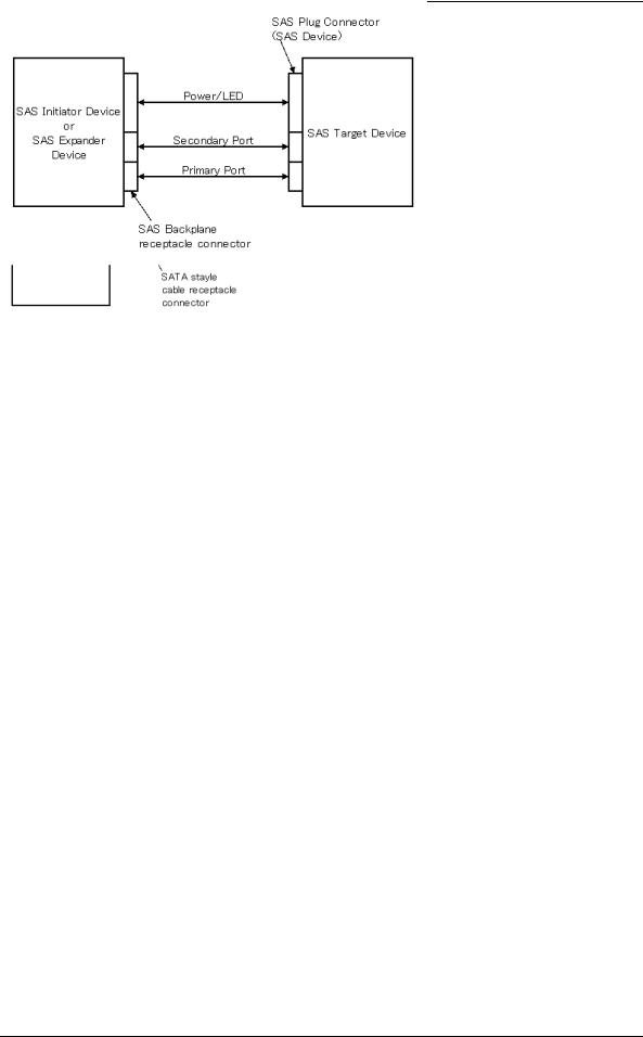
For the Serial Attached SCSI, the ANSI standard defines Point-to-Point technology. Figure 1.1 and Figure 1.2 give examples of the SAS system configuration.
Figure 1.1 Example of SAS system configuration (Dual port internal cabled environment)
Figure 1.2 Example of SAS system configuration (Dual port internal backplane environment)
(1)Port addressing
Every device connected with the SAS protocol has a unique address (SAS address). SAS addresses are in the Name Address Authority (NAA) IEEE Registered format defined by SCSI Primary Command-3 (SPC-3).
An SAS address consists of 8 bytes as a unique value set for each device.
The INIT can implement an I/O operation on a disk drive by using the corresponding SAS address stored by the HDDs.
1-6 |
C141-E237 |

CHAPTER 2 Specifications
2.1Hardware Specifications
This chapter describes specifications of the HDDs.
2.1Hardware Specifications
2.1.1Model name and order number
Each model has different recording capacities when shipped. Table 2.1 lists the model name and order number.
The data format can be changed by reinitializing with the user's system.
Table 2.1 Model names and order numbers
Model name |
Order number |
Interface type |
Capacity |
|
(user area) |
||||
|
|
|
||
|
|
|
|
|
MAX3147RC |
CA06697-B400 |
SAS |
147 GB (*) |
|
|
|
|
|
|
MAX3073RC |
CA06697-B200 |
SAS |
73.5 GB (*) |
|
|
|
|
|
|
MAX3036RC |
CA06697-B100 |
SAS |
36.7 GB (*) |
|
|
|
|
|
(*) 1 GB = 1,000,000,000 bytes
C141-E237 |
2-1 |

Specifications
2.1.2Function specifications
Table 2.2 shows the function specifications of the HDDs.
|
|
Table 2.2 |
Function specifications |
|
|||
|
|
|
|
|
|
|
|
Item |
|
|
|
Specification |
|
||
|
|
|
|
|
|
||
MAX3147RC |
|
MAX3073RC |
|
MAX3036RC |
|||
|
|
|
|
||||
|
|
|
|
|
|
|
|
Formatted capacity/device (*1) |
147 GB (*2) |
|
73.5 GB (*2) |
|
36.7 GB (*2) |
||
|
|
|
|
|
|
|
|
Number of disks |
|
4 |
|
2 |
|
1 |
|
|
|
|
|
|
|
|
|
Number of heads |
|
8 |
|
4 |
|
2 |
|
|
|
|
|
|
|
|
|
Number of rotations min-1 (rpm) |
|
|
15,000 ± 0.2 % |
|
|
||
|
|
|
|
|
|
|
|
Average latency time |
|
|
|
2.0 ms |
|
||
|
|
|
|
|
|
|
|
|
Track to Track |
|
|
|
0.2 ms / 0.4 ms |
|
|
Seek time (*3) |
Average |
|
|
|
3.3 ms / 3.8 ms |
|
|
(Read/Write) |
|
|
|
|
|
|
|
|
Full stroke |
|
|
|
8.0 ms / 9.0 ms |
|
|
|
|
|
|
|
|
|
|
Start/stop time |
Start time |
|
|
|
30 s typ. (60 s max.) |
|
|
(*4) |
Stop time |
|
|
|
30 s typ. |
|
|
|
|
|
|
|
|||
|
|
|
|
|
|
|
|
Recording mode |
|
|
|
60/63 MEEPR4ML |
|
||
|
|
|
|
|
|
|
|
|
Height: |
|
|
|
25.4 mm |
|
|
External |
Width: |
|
|
|
101.6 mm |
|
|
dimensions |
|
|
|
|
|||
|
|
|
|
|
|
|
|
|
Depth: |
|
|
|
146.0 mm |
|
|
|
|
|
|
|
|
|
|
Weight |
|
|
|
|
0.8 kg max. |
|
|
|
|
|
|
|
|
||
Power consumption (*5) |
|
|
|
11.5 W typ. |
|
||
|
|
|
|
|
|
|
|
Interface |
SAS |
|
|
|
Cable length: 8 m max |
|
|
|
|
|
|
|
|
|
|
Areal density |
|
|
|
|
58 Gbit/inch2 |
|
|
|
|
|
|
|
|
|
|
Data transfer |
Disk drive |
|
|
|
147 MB/s |
|
|
|
|
|
|
|
|
|
|
rate (*6) |
SAS |
|
|
|
1.5 Gbps, 3 Gbps |
|
|
|
|
|
|
|
|||
|
|
|
|
||||
Logical data block length |
|
512 to 528 byte (Fixed length) (*7) |
|||||
|
|
|
|||||
|
|
SAS (T10/1562D Rev. 05), SAS1.1 (T10/1601D Rev. 07), |
|||||
Command specification |
SAM-3 (T10/1561D Rev. 14), SAM-2 (T10/1157D Rev. 24), |
||||||
|
|
SPC-2 (T10/1236D Rev. 20), SBC (T10/996D Rev. 8c) |
|||||
|
|
|
|
|
|
||
Data buffer |
|
|
|
16 MB FIFO ring buffer (*8) |
|
||
|
|
|
|
|
|
||
Acoustic noise (Idle) |
|
|
|
3.5 Bels typ. |
|
||
|
|
|
|
|
|
|
|
(*1) The formatted capacity can be changed by changing the logical block length and using spare sector space. See Chapter 3 for the further information. The formatted capacity listed in the table is an estimate for 512 bytes per sector.
(*2) 1 GB = 1,000,000,000 bytes
2-2 |
C141-E237 |

2.1 Hardware Specifications
(*3) The seek time is as follows:
Seek time [ms]
Seek Difference [4096 Cyl/div]
(*4) The start time is the time from power on or start command to when the HDDs are ready, and the stop time is the time for disks to completely stop from power off or stop command.
(*5) This value indicates in idle mode. Power supply at nominal voltage ±1%. 25°C ambient.
(*6) The maximum data transfer rate may be restricted to the response speed of initiator and by transmission characteristics. 1 MB/s = 1,000,000 bytes/s.
(*7) Refer to 1.1 (12).
(*8) 1 MB = 1,048,576 bytes.
C141-E237 |
2-3 |

Specifications
2.1.3Environmental specifications
Table 2.3 lists environmental and power requirements.
|
Table 2.3 |
Environmental/Power requirements |
|
|||||
|
|
|
|
|
|
|
|
|
|
Item |
|
|
|
|
Specification |
|
|
|
|
|
|
|
|
|
|
|
|
|
|
MAX3147RC |
|
MAX3073RC |
|
MAX3036RC |
|
|
|
|
|
|
|
|||
|
|
|
|
|
|
|
|
|
|
Operating |
|
|
|
|
5 to 55 °C |
|
|
|
|
|
|
|
|
|
|
|
|
Non-operating |
|
|
|
–40 to 70 °C |
|
||
Temperature |
|
|
|
|
|
|
||
Transport (within a week) |
|
|
–40 to 70 °C |
|
||||
(*1) |
|
|
|
|
|
|
|
|
DE surface temperature at |
|
|
5 to 60 °C |
|
||||
|
|
|
|
|||||
|
operating |
|
|
|
|
|
||
|
|
|
|
|
|
|
|
|
|
|
|
|
|
|
|
|
|
|
Gradient |
|
|
|
|
15 °C/h or less |
|
|
|
|
|
|
|
|
|
|
|
|
Operating |
|
|
|
|
5 to 95 %RH |
|
|
|
|
|
|
|
|
|
|
|
Relative |
Non operating |
|
|
|
5 to 95 %RH |
|
||
|
|
|
|
|
|
|
|
|
Transport (within a week) |
|
|
5 to 95 %RH |
|
||||
humidity |
|
|
|
|||||
|
|
|
|
|
|
|
|
|
|
Maximum wet bulb |
|
|
29 °C (no condensation) |
|
|||
|
temperature |
|
|
|
|
|||
|
|
|
|
|
|
|
|
|
|
|
|
|
|
||||
|
Operating (*3) |
|
0.6 mm (5 to 20Hz) / 9.8 m/s2 (1G) (20 to 300 Hz) or less |
|||||
Vibration (*2) |
Non-operating (*4) |
|
3.1 mm (5 to 20Hz) / 49 m/s2 (5G) (20 to 300Hz) or less |
|||||
|
Transport (packaged) |
|
3.1 mm (5 to 20Hz) / 49 m/s2 (5G) (20 to 300Hz) or less |
|||||
|
Operating |
|
|
|
637.4 m/s2 (65G) (2ms) |
|
||
Shock (*2) |
Non-operating |
|
|
2451.7 m/s2 (250G) (2ms) |
|
|||
|
Transport (packaged) |
|
|
2451.7 m/s2 (250G) (2ms) |
|
|||
Altitude |
Operating |
|
|
–305 to +3,048 m (–1,000 to +10,000 feet) |
||||
|
|
|
|
|
|
|
|
|
Non-operating |
|
–305 to +12,192 m (–1,000 to +40,000 feet) |
||||||
|
|
|||||||
|
|
|
|
|
|
|
|
|
|
|
Ready |
|
|
|
0.75 A |
|
|
|
|
(Average) |
|
|
|
|
||
|
|
|
|
|
|
|
|
|
|
|
|
|
|
|
|
|
|
|
+12V DC |
Peak within |
|
|
3.0 A |
|
||
|
100 us at |
|
|
|
|
|||
|
±5 % |
spin-up |
|
|
|
|
|
|
|
|
|
|
|
|
|
|
|
|
|
Random |
|
|
|
1.0 A |
|
|
Power |
|
W/R (about |
|
|
|
|||
|
80 IOPS) |
|
|
|
|
|
|
|
requirements |
|
|
|
|
|
|
|
|
|
|
|
|
|
|
|
|
|
(*5) |
|
Ready |
|
|
|
0.45 A |
|
|
|
|
(Average) |
|
|
|
|
||
|
+5V DC |
|
|
|
|
|
|
|
|
|
|
|
|
|
|
|
|
|
Random |
|
|
|
|
|
|
|
|
±5 % |
|
|
|
1.0 A |
|
||
|
W/R (about |
|
|
|
||||
|
|
|
|
|
||||
|
|
80 IOPS) |
|
|
|
|
|
|
|
|
|
|
|
|
|
|
|
|
Ripple |
|
|
|
250mVp-p or less (*6) |
|
||
|
(+5V, +12V) |
|
|
|
|
|||
|
|
|
|
|
|
|
|
|
|
|
|
|
|
|
|
|
|
2-4 |
C141-E237 |

2.1 Hardware Specifications
(*1) For detail condition, see Section 4.1.
(*2) Vibration applied to the drive is measured at near the mounting screw hole on the frame as much as possible.
(*3) At random seek write/read and default on retry setting with log sweep vibration.
(*4) At power-off state after installation
Vibration displacement should be less than 2.5 mm.
(*5) Input voltages are specified at the drive connector side, during drive ready state. (*6) High frequency noise (over 20MHz) is less than 100 mVp-p.
2.1.4Error rate
Errors detected during initialization and replaced by alternate block assignments are not included in the error rate. Data blocks to be accessed should be distributed over the disk medium equally.
(1)Unrecoverable error rate
Errors which cannot be recovered within 63 retries and ECC correction should not exceed 10 per 1016 bits read.
(2)Positioning error rate
Positioning errors which can be recovered by one retry should be 10 or less per 108 seeks.
2.1.5Reliability
(1)Mean Time Between Failures (MTBF)
MTBF of the HDDs during their life time is 1,400,000 hours (operating: 24 hours/day, 7 days/week average DE surface temperature: 50°C or less).
Note:
The MTBF is defined as:
Operating time (hours) at all field sites
MTBF =
The number of equipment failures from all field sites
Failure of the equipment means failure that requires repair, adjustments, or replacement. Mishandling by the operator, failures due to bad environmental conditions, power trouble, host system trouble, cable failures, or other failures not caused by the equipment are not considered.
C141-E237 |
2-5 |
Specifications
(2)Mean Time To Repair (MTTR)
MTTR is the average time taken by a well-trained service mechanic to diagnose and repair a drive malfunction. The drive is designed for a MTTR of 30 minutes or less.
(3)Service life
The service life under suitable conditions and treatment is as follows.
The service life is depending on the environment temperature. Therefore, the user must design the system cabinet so that the average DE surface temperature is as low as possible.
• |
DE surface temperature: 40°C or less |
5 years |
• |
DE surface temperature: 41°C to 45°C |
4.5 years |
• |
DE surface temperature: 46°C to 50°C |
4 years |
• |
DE surface temperature: 51°C to 55°C |
3.5 years |
• |
DE surface temperature: 56°C to 60°C |
3 years |
• |
DE surface temperature: Exceeding 60°C |
Without warranty |
|
|
(Keep the DE surface temperature 60 °C or less.) |
Even if the HDDs are used intermittently, the longest service life is 5 years.
Note:
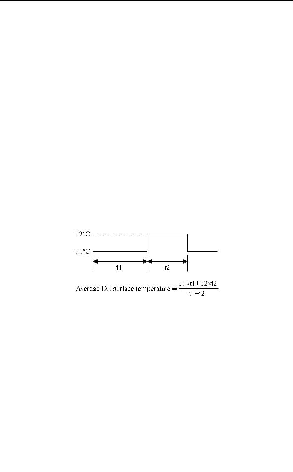
The "average DE surface temperature" means the average temperature at the DE surface throughout the year when the HDDs are operating.
(4)Data security at power failure
Integrity of the data on the disk is guaranteed against all forms of DC power failure except on blocks where a write operation is being performed. The above does not applied to formatting disks or assigning alternate blocks.
2-6 |
C141-E237 |

CHAPTER 3 Data Format
3.1Data Space
3.2Logical Data Block Addressing
3.3Defect Management
This chapter explains data space definition, logical data block addressing, and defect management on the HDDs.
3.1Data Space
The HDDs manage the entire data storage area divided into the following three data spaces.
•User space: Storage area for user data
•Internal test space: Reserved area for diagnostic purposes
•System space: Area for exclusive use of HDDs themselves
The user space allows a user access by specifying data. These spaces can be accessed with the logical data block addressing method described in Section 3.2. The internal test space is used by Read/write test of self-diagnostics test, but user can’t use direct access. The system space is accessed inside the HDDs at power-on or during the execution of a specific command, but the user cannot directly access the system space.
3.1.1Cylinder configuration
The HDDs allocate cylinders to the user space, internal test space, and system space. Figure 3.1 is the cylinder configuration.
Spare areas (alternate areas) for defective sectors are provided in the user space. Several sectors in the last track of one cell and the last cylinder (alternate cylinders) in one zone are allocated as alternate areas according to the user's assignment (MODE SELECT command). See Subsection 3.1.2 for details.
C141-E237 |
3-1 |
Loading...