


COPYRIGHT
Fujitsu™ PC Corporation has made every eVort to ensure the accuracy and completeness of this document. However, as ongoing development eVorts are continually improving the capabilities of our products, we cannot guarantee the accuracy of the contents of this document. We disclaim liability for errors, omissions, or future changes.
LifeBook, Fujitsu,and the Fujitsu logo are trademarks of Fujitsu Limited.
The following are registered trademarks of IBM Corporation:IBM, IBM PC AT, IBM PS/2. The following are registered trademarks of
Microsoft Corporation:MS,MS-DOS, Windows 95. PCMCIA is a trademark of the Personal Computer Memory Card International Association.
Phoenix and the Phoenix logo are registered trademarks of Phoenix Technologies,Ltd. Pentium is a registered trademark and
MMX technology is a registered trademark of Intel Corporation.
PC-Doctor is a trademark of watergate.software.inc.
SoftPEG is a registered trademark of CompuCore Multimedia Inc.
LapLink is a registered trademark of Traveling Software Inc.
AudioRack is a registered trademark of ESS Technology, Inc.
MegaPhone is a registered trademark of Cypress Research Corporation
All other trademarks mentioned herein are the property of their respective owners.
We cannot guarantee the accuracy of the contents of this document. We disclaim liability for errors, omissions, or future changes.
© Copyright 1996 Fujitsu PC Corporation. All rights reserved. No part of this publication may be copied, reproduced, or translated, without prior written consent of Fujitsu PC Corporation. No part of this publication may be stored or transmitted in any electronic form without the written consent of Fujitsu PC Corporation.
DECLARATION OF CONFORMITY according to FCC Part 15
Responsible Party Name: Fujitsu PC Corporation
Address: 598 Gibraltar Drive Milpitas,CA 95035
Telephone: (408) 935-8800
Declares that product: Model:LifeBook 565Tx. LifeBook 585Tx.
Complies with Part 15 of the FCC Rules.
This device complies with Part 15 of the FCC rules. Operations is subject to the following two conditions:
(1) This device must not be allowed to cause harmful interference, (2) This device must accept any interference received, including interference that may cause undesired operation.
David Woo |
Fujitsu |
9/15/97 |
full name |
company |
date |

C A U T I O N
Changes or modification not expressly approved by Fujitsu™ PC Corporation could void this user’s authority to operate the equipment.
FCC NOTICES
Notice to Users of Radios and Television
These limits are designed to provide reasonable protection against harmful interference in a residential installation. This equipment generates,uses, and can radiate radio frequency energy and, if not installed and used in accordance with the instructions,may cause harmful interference to radio communications. However, there is no guarantee that interference will not occur in a particular installation. If this equipment does cause harmful interference to radio or television reception, which can be determined by turning the equipment oV and on, the user is encouraged to try to correct the interference by one or more of the following measures:
■Reorient or relocate the receiving antenna.
■Increase the separation between the equipment and receiver.
■Connect the equipment into an outlet that is on a diVerent circuit than the receiver.
■Consult the dealer or an experienced radio/TV technician for help.
Shielded interconnect cables must be employed with this equipment to ensure compliance with the pertinent RF emission limits governing this device.
Notice to Users of the US Telephone Network
The LifeBook™ 500 Series notebook computers are supplied with an internal modem which complies with Part 68 of the FCC rules.On this notebook is a label that contains the FCC Registration Number and the Ringer Equivalence Number (REN) for this equipment among other information. If requested, the user must provide their telephone company with the following information:
1.The telephone number to which the notebook is connected.
2.The Ringer Equivalence Number (REN) for this equipment.
3.That the equipment requires a standard modular jack type USOC RJ-11C which is FCC
Part 68 compliant.
4.The FCC Registration Number.
This equipment is designed to be connected to the telephone network or premises wiring using a standard modular jack type USOC RJ-11C which is FCC Part 68 compliant and a line cord between the modem and the telephone network with a minimum of 26AWG.
The REN is used to determine the number of devices that you may connect to your telephone line and still have all of those devices ring when your number is called. Too many devices on one line may result in failure to ring in response to an incoming call. In most, but not all,areas the sum of the RENs of all of the devices should not exceed five (5.0). To be certain of the number of devices you may connect to your line, as determined by the RENs, contact your local telephone company.
If this equipment causes harm to the telephone network, your telephone company may discontinue your service temporarily. If possible,they will notify you in advance. If advance notice is not practical they will
notify you as soon as possible. You will also be advised of your right to file a complaint with the FCC.
This fax modem also complies with fax branding requirements per FCC Part 68.
If you experience trouble with this equipment please contact your support representative,
toll free at 1-800-8FUJITSU (1-800-838-5487) or Fujitsu Computer Products of America (FCPA), 7300 NE Evergreen Parkway, Hillsboro, OR 97124, telephone 503-681-7300.
Your telephone company will probably ask you to disconnect this equipment from the telephone network until the problem is corrected and you are sure that the equipment is not malfunctioning.
This equipment may not be used on coin service telephones provided by your telephone company. Connection to party lines is subject to state tariVs.
Contact your state’s public utility commission,public service commission or corporation commission for more information.
This equipment includes automatic dialing capability. When programming and/or making test calls to emergency numbers:
■Remain on the line and briefly explain to the dispatcher the reason for the call.
■Perform such activities in oV-peak hours, such as early morning or late evening.
FCC rules prohibit the use of non-hearing aid compatible telephones in the following locations or applications:
■All public or semipublic coin-operated or credit card telephones.
■Elevators,highways, tunnels (automobile, subway, railroad or pedestrian) where a person with impaired hearing might be isolated in an emergency.
■Places where telephones are specifically installed to alert emergency authorities such as fire, police or medical assistance personnel.
■Hospital rooms, residential health care facilities, convalescent homes and prisons.
■Workstations for the hearing impaired.
■Hotel,motel or apartment lobbies.
■Stores where telephones are used by patrons to order merchandise.
■Public transportation terminals where telephones are used to call taxis or to rese rve lodging or rental cars.
■In hotel and motel rooms as at least ten percent of the rooms must contain hearing aid compatible
telephones or jacks for plug-in hearing aid compatible telephones which will be provided to hearing impaired customers on request.
DOC (INDUSTRY CANADA) NOTICES
Notice to Users of Radios and Television
This Class B digital apparatus meets all requirements of the Canadian Interference-Causing Equipment Regulations.
CET appareil numérique de la class B respecte toutes les exigence du Réglement sur le matérial brouilleur du Canada.
Notice to Users of the Canadian
Telephone Network
The Canadian Industry Canada label identifies certified equipment. This certification means that the equipment meets certain telecommunications network protective, operational and safety requirements. The Department does not guarantee the equipment will operate to the user’s satisfaction.
The LifeBook™ 500 Series notebook computers are supplied with an internal modem which complies with the Industry Canada certification standards for telecommunication network protection and safety requirements. Before connecting this equipment to a telephone line the user should ensure that it is permissible to connect this equipment to the local telecommunication facilities. The user should be aware that compliance with the certification standards does not prevent service degradation in some situations.
Repairs to telecommunication equipment should be made by a Canadian authorized maintenance facility. Any repairs or alterations not expressly approved by Fujitsu™ PC Corporation or any equipment failures may give the telecommunication company cause to request the user to disconnect the equipment from the telephone line.

The connecting arrangement code for this equipment is CA11A.
The Load Number is 3.
The Load Number assigned to each telephone terminal device denotes the percentage of the total load to be connected to a telephone loop or circuit which is used by the device to prevent overloading. The termination on a loop may consist of any combination of devices such that the total of the load numbers of all devices does not exceed 100.
C A U T I O N
For safety, users should ensure that the electrical ground of the power utility, the telephone lines and the metallic water pipes are connected together. Users should NOT attempt to make such connections themselves but should contact the appropriate electric inspection authority or electrician. This may be particularly important in rural areas.
Avis Aux Utilisateurs Du Réseau
Téléphonique Canadien
L’étiquette canadienne Industrie Canada identifie l’équipement certifié. Cette certification signifie que l’équipement satisfait certaines normes de protection,d’exploitation et de sécurité des réseaux de télécommunications. Le département ne garantit pas le fonctionnement de l’équipement à la satisfaction de l’utilisateur.
La série LifeBook™ 500 possèdent un modem interne conforme aux normes de certification d’Industrie Canada pour protéger les réseaux de télécommunications et satisfaire aux normes
de sécurité. Avant de connecter cet équipement à une ligne téléphonique,l’utilisateur doit vérifier s’il est permis de connecter cet équipement aux installations de télécommunications locales. L’utilisateur est averti que même la conformité aux normes de certification ne peut dans certains cas empêcher la dégradation du service.
Les réparations de l’équipement de télécommunications doivent être eVectuées par un service de maintenance agréé au Canada. Toute réparation ou modification, qui n’est pas expressément approuvée par Fujitsu PC Corp.,
ou toute défaillance de l’équipement peut entraîner la compagnie de télécommunications à exiger que l’utilisateur déconnecte l’équipement de la ligne téléphonique.
Le code d’arrangement de connexion de cet équipement est CA11A.
Le numéro de charge est 3.
Le numéro de charge assigné à chaque terminal téléphonique indique le pourcentage de la charge totale pouvant être connecté à une boucle ou à un circuit téléphonique, utilisé par ce périphérique afin de prévenir toute surcharge. La terminaison d’une boucle peut être constituée de n’importe quelle combinaison de périphériques de sorte que le total de numéros de charge de tous les périphériques n’excède pas 100.

A V E R T I S S E M E N T
Pour assurer la sécurité, les utilisateurs doivent vérifier que la prise de terre du service d’électricité, les lignes téléphoniques et les conduites d’eau métalliques sont connectées
ensemble. Les utilisateurs NE doivent PAS tenter d’établir ces connexions eux-mêmes, mais doivent contacter les services d’inspection d’installations électriques appropriés ou un électricien. Ceci peut être particulièrement important en régions rurales.
UL NOTICE (FOR AUTHORIZED REPAIR TECHNICIANS ONLY)
CAUTION: For continued protection against risk of fire, replace only with the same type and rating fuse.
CAUTION:Danger of explosion if CMOS battery is incorrectly replaced. Replace only with the same or equivalent type recommended by the manufacturer. Dispose of used batteries according to the manufacturer’s instruction.
WARNING: CMOS and NiCAD batteries may explode if mistreated. Do not recharge,disassemble or dispose of in fire.
Black & White
of Cover (to come)

T a b l e o f C o n t e n t s

T a b l e o f C o n t e n t s
PREFACE . . . . . . . . . . . . . . . . . . . . v
SECTION ONE |
|
SETTING UP YOUR LIFEBOOK 500 |
|
SERIES |
|
Unpacking. . . . . . . . . . . . . . . . . . . |
. 2 |
Overview of Features . . . . . . . . . . . . . |
. 3 |
Component Identification . . . . . . . . . . . |
4 |
Top and Front Components . . . . . . . . . . |
4 |
Left Side Panel Components . . . . . . . . . . |
6 |
Right Side Panel Components . . . . . . . . . |
7 |
Rear Panel Components . . . . . . . . . . . . |
8 |
Bottom Components . . . . . . . . . . . . . . |
9 |
MediaConnect . . . . . . . . . . . . . . . . . |
10 |
Power Sources . . . . . . . . . . . . . . . . . |
11 |
Data Security . . . . . . . . . . . . . . . . . |
12 |
Starting Your Notebook for the First Time. . |
13 |
User Registration . . . . . . . . . . . . . . . |
15 |
Learning About Your Operating System |
|
and Application Software. . . . . . . . . . |
15 |
SECTION TWO
USING YOUR LIFEBOOK 500 SERIES
Built-in Display . . . . . . . . . . . . . . . . |
18 |
Adjusting the Keyboard Angle . . . . . . . . |
18 |
Status Indicator Panel . . . . . . . . . . . . . |
19 |
Power On . . . . . . . . . . . . . . . . . . . |
23 |
Power Off . . . . . . . . . . . . . . . . . . . |
24 |
Restarting the System . . . . . . . . . . . . . |
25 |
Fujitsu Welcome Center. . . . . . . . . . . . |
25 |
Batteries . . . . . . . . . . . . . . . . . . . . |
25 |
Integrated Touchpad Pointing Device . . . . |
29 |
Using the Keyboard . . . . . . . . . . . . . . |
32 |
Using the Volume Control . . . . . . . . . . |
33 |
Floppy Disk Drive . . . . . . . . . . . . . . . |
34 |
CD-ROM Drive . . . . . . . . . . . . . . . . |
37 |
Hard Drive . . . . . . . . . . . . . . . . . . . |
38 |
Power Management . . . . . . . . . . . . . . |
39 |
Internal Modem . . . . . . . . . . . . . . . . |
46 |
Infrared Port . . . . . . . . . . . . . . . . . . |
46 |
Pre-Installed Software . . . . . . . . . . . . . |
47 |
SECTION THREE
CONFIGURING YOUR LIFEBOOK 500 SERIES
Boot Sequence . . . . . . . . . . . . . . . . . 52 Identifying the Drives . . . . . . . . . . . . . 52 BIOS Setup Utility. . . . . . . . . . . . . . . 53 Navigating Through the Setup Utility . . . . 54 Main Menu – Setting System Parameters . . 56 Advanced Menu – Setting Device Controls . 65 Security Menu – Setting Passwords. . . . . . 79 Power Savings Menu – Setting Power
Management Controls . . . . . . . . . . . 83 Exit Menu – Leaving the Setup Utility . . . . 88 Setting Up Your Save-To-Disk
File Allocation. . . . . . . . . . . . . . . . 91
ii
L i f e B o o k 5 0 0 S e r i e s f r o m F u j i t s u
T a b l e o f C o n t e n t s
SECTION FOUR
USER INSTALLABLE FEATURES
Multi-function Bay Devices. . . . . . . . . . 95
PC Cards . . . . . . . . . . . . . . . . . . . . 97 Main Lithium ion Battery. . . . . . . . . . . 99 Parallel Port Devices . . . . . . . . . . . . . 101 Mouse or Keyboard . . . . . . . . . . . . . 101 Microphone . . . . . . . . . . . . . . . . . 101 Stereo Line In Devices . . . . . . . . . . . . 101 Audio Output Devices . . . . . . . . . . . . 101 Telephone Lines . . . . . . . . . . . . . . . 102 USB Devices . . . . . . . . . . . . . . . . . 102 External Monitor . . . . . . . . . . . . . . . 102 Theft Prevention Lock . . . . . . . . . . . . 102 MediaConnect . . . . . . . . . . . . . . . . 102 Serial Port Devices . . . . . . . . . . . . . . 104 TVs . . . . . . . . . . . . . . . . . . . . . . 104 MIDI or Game Devices . . . . . . . . . . . 104 External Installation of the Floppy
Disk Drive . . . . . . . . . . . . . . . . . 105 Memory Upgrade Module . . . . . . . . . . 106 Mini-Docking Station . . . . . . . . . . . . 109
SECTION FIVE
TROUBLESHOOTING
Identifying the Problem . . . . . . . . . . . 114
Specific Problems . . . . . . . . . . . . . . 115 Power On Self Test Messages . . . . . . . . 134 Emergency CD-ROM
Tray Release . . . . . . . . . . . . . . . . 136 Installing and Removing
the Internal Hard Drive . . . . . . . . . . 137 Modem Setup and Commands . . . . . . . 138 Restoring Your Pre-installed Software
from CD-ROM . . . . . . . . . . . . . . 138
SECTION SIX |
|
CARE AND MAINTENANCE |
|
Care and Maintenance . . . . . . . . . . . . |
140 |
Caring for Your Notebook . . . . . . . . . . |
140 |
Increasing Battery Life . . . . . . . . . . . . |
141 |
Caring for Your Batteries . . . . . . . . . . |
141 |
APPENDIX A SPECIFICATIONS |
|
Warranty . . . . . . . . . . . . . . . . . . . |
144 |
LifeBook™ 565Tx Specifications . . . . . . . |
144 |
LifeBook 585Tx Specifications . . . . . . . |
147 |
Approvals . . . . . . . . . . . . . . . . . . . |
150 |
Popular Accessories . . . . . . . . . . . . . |
150 |
APPENDIX B GLOSSARY . . . . . . |
152 |
INDEX . . . . . . . . . . . . . . . . . . . |
159 |
iii

P r e f a c e
L i f e B o o k ™ 50 0 Se rie s fr o m F u jitsu ™

P r e f a c e
PREFACE
The LifeBook™ 500 Series from Fujitsu™ PC Corporation is a powerful notebook computer. It is powered by an Intel Pentium® microprocessor with MMX™ technology, has a built-in color display, a CD-ROM drive and brings
the computing power of desktop personal computers (PCs) to a portable environment.
This manual explains how to operate your LifeBook 500 Series’ hardware and built-in system software. The LifeBook 500 Series is compatible with the IBM PC AT®. It comes with Windows® 95.
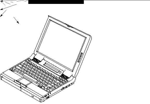
A LifeBook 500 Series is a completely selfcontained unit with an active-matrix (TFT) color LCD display. It has a powerful interface that enables it to support a variety of optional features. (Figure P-1.)
CONVENTIONS USED IN THE GUIDE
Screen examples in this manual are intended as examples only, and screen and file names may diVer in actual use.
Messages displayed by the LifeBook 500 Series appear in Courier type.
Example: Shutdown the computer?
Commands that you enter into the computer using the keyboard appear in Courier type. Example: Fujitsu .
Keyboard keys are shown in boldface
Helvetica type.
Example: Fn, F1, Esc, and Ctrl.
Pages with additional information about a specific topic are cross-referenced within the text. Example: (See page xx.)
P O I N T
The point icon highlights information that will enhance your understanding of the subject material.
C A U T I O N
The caution icon highlights information that is important to your safety, to the safe operation of your computer, or to the integrity of your files. Please read all caution information carefully.
vi

L i f e B o o k ™ 5 0 0 S e r i e s f r o m F u j i t s u ™
L i f e B o o k 5 0 0 S e r i e s f r o m F u j i t s u
Figure P-1 LifeBook 500 Series
with Both Fujitsu and
Third Party Options
vii

S e c t i o n O n e
S etting Up Your LifeBook™ 500 Series
Unpacking . . . . . . . . . . . . . . . . . . . 2
Overview of Features . . . . . . . . . . . . . 3
Component Identification . . . . . . . . . . . 4
Top and Front Components . . . . . . . . . . 4
Left Side Panel Components . . . . . . . . . . 6
Right Side Panel Components . . . . . . . . . 7
Rear Panel Components . . . . . . . . . . . . 8
Bottom Components. . . . . . . . . . . . . . 9
MediaConnect . . . . . . . . . . . . . . . . 10
Power Sources . . . . . . . . . . . . . . . . 11
Data Security . . . . . . . . . . . . . . . . . 12
Starting Your Notebook for the First Time . . 13
User Registration . . . . . . . . . . . . . . . 15
Learning About Your Operating System
and Application Software. . . . . . . . . . 15
S e c t i o n O n e
SECTION ONE
SETTING UP YOUR LIFEBOOK™ 500 SERIES FROM FUJITSU™
This section describes how to set up your
LifeBook 500 Series from Fujitsu. We strongly recommend that you read it before using your notebook – even if you are already familiar with notebook computers.
UNPACKING
When you receive your computer, unpack it carefully, and compare the parts you have received with the items listed below.
For a standard configuration you should have:
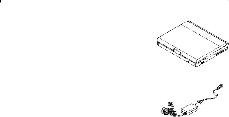
■LifeBook 500 Series from Fujitsu. (Figure 1-1.)
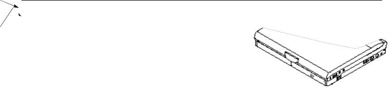
■AC adapter with AC power cord
(located in the accessories box). (Figure 1-2.)
■Main Lithium ion battery
(already installed in the computer).
■Modular 20-speed maximum CD-ROM drive (already installed in the computer).
■Modular 3.5" floppy disk drive
(located in the accessories box). (Figure 1-4.)
■MediaConnect
(located in the accessories box.) (Figure 1-3.)
■External floppy disk drive adapter
(located in the accessories box). (Figure 1-5.)
■RJ-11 cable
(located in the accessories box).
■User’s Guide.
■Registration card and customer information pack.
■Microsoft Windows® 95 Manual.
■Recovery CD-ROM
(located in the accessories box).
■Additional equipment and documentation depending on the option package you have purchased.
Figure 1-1 LifeBook 500 Series Computer
Figure 1-2 AC Adapter Unit
2

Figure 1-3 MediaConnect
Figure 1-4 Floppy Disk Drive
Once you have checked and confirmed that your notebook system is complete, connect the AC adapter and follow the instructions on page 12 to accept the conditions for using the
LifeBook 500 Series. When you have completed the setup process please complete and send in your registration card.
S e t t i n g U p Y o u r L i f e B o o k 5 0 0 S e r i e s
Figure 1-5 External Floppy Disk Drive Adapter
OVERVIEW OF LIFEBOOK 500 SERIES FEATURES
The LifeBook 500 Series is a compact, yet powerful notebook computer available with standard features including: (See Appendix A, pages 144–151, for detailed information.)
■166MHz or 233MHz Intel Pentium processor with MMX™ technology .
■32MB SDRAM standard, expandable to 96MB.
■12.1" active-matrix (TFT) color display with 1024 x 768 resolution (XGA).
L i f e B o o k ™ 5 0 0 S e r i e s f r o m F u j i t s u ™
■2MB Video RAM.
■Built-in 2GB or 4GB hard drive.
■Main Lithium ion battery.
■Multi-function bay which supports the following:
■3.5" floppy disk drive (included with all models).
■20-speed maximum CD-ROM drive (included with all models).
■Optional second 1.3GB hard drive.
■Optional second Lithium ion battery.
■Internal 33.6 fax/data/voice modem.
■Full audio and video features:
■16-bit SoundBlaster-compatible sound chip.
■3D-Stereo for multiple speaker effect.
■Built-in stereo speakers and microphone.
■NTSC/PAL and S-Video support for TV presentations.
3
S e c t i o n O n e
■Stereo line in jack.
■Microphone jack.
■Stereo headphone jack.
■MPEG-1 player and Zoomed Video support for full motion video.
■Universal Serial Bus (USB) port for a multitude of devices.
■Two Type II/one Type III PC Card slots.
■Fast IrDA 1.1 compatible infrared port for wireless data transfer.
■Integrated touchpad pointing device for easy cursor control.
■External monitor support with simultaneous display capabilities.
■Standard external floppy disk drive adapter.
■“No re-learning”, full-size keyboard with three dedicated Windows® 95 keys.
■Hot swap connection for an external keyboard or an external mouse.
■Bridge battery for warm-swapping capabilities for batteries.
■Standard pre-installed software:
■Microsoft® Windows® 95.
■LapLink® for file transfers via modem, cable or infrared port.
■PC-Doctor™ for system diagnostics.
■SoftPEG® from CompCore,an MPEG-1 video player.
■McAfee VirusScan for virus protection.
■ESS AudioRack® for 3D-Stereo, audio CD, and other audio controls.
■MegaPhone® for telephone applications including fax,dialing, speakerphone and Caller-ID.
■Some models may include additional software.
COMPONENT IDENTIFICATION
For detailed specifications refer to Appendix A on pages 144–151.
|
|
Theft Prevention Lock Slot |
|
|
Power Switch |
Display |
|
DC Power |
Latch |
CD Tray |
Jack |
|
PS/2 Port |
|
|
Release |
|
|
Multi-function Bay Module Release |
|
|
|
|
|
|
Figure 1-6 Top and Front Panel |
TOP AND FRONT COMPONENTS
Display Panel Latch
This latch locks and releases the display panel.
(Figure 1-6.)
Display Panel
This is a color LCD panel with back lighting for the display of text and graphics. (Figure 1-7.)
Brightness Control
The brightness control adjusts the overall intensity of the display screen back lighting.
(Figure 1-7.)
4
L i f e B o o k ™ 5 0 0 S e r i e s f r o m F u j i t s u ™
S e t t i n g U p Y o u r L i f e B o o k 5 0 0 S e r i e s
Status Indicator
Stereo Speaker
Keyboard
Touchpad Pointing Device
Multi-function Bay
Display Panel
Brightness Control
Suspend/Resume Button
Closed Cover Switch
 Stereo Speaker
Microphone Jack |
|
Headphone Jack |
|
Volume Control |
|
Stereo Line In Jack |
Figure 1-7 LifeBook 500 Series with Display Open |
5
S e c t i o n O n e
Status Indicator
LCD display of the status of the power and power source, Suspend mode,battery charge (both main and optional second), floppy disk drive activity, hard drive activity, CD-ROM drive activity, PC Card activity, CapsLock, Num Lk and Scr Lk. (Figure 1-7.)
Suspend/Resume Button
The Suspend/Resume button allows you to suspend computer activity without turning off your notebook power, and to return it to an active state. This feature saves power, and is particularly useful when your notebook is running only on battery power. (See pages 39–40 for more information on Power Management. (Figure 1-7.)
C A U T I O N
Be sure you know what settings are active for your Suspend/Resume button before you use it because misuse can result in data loss. (See the Power Savings Menu of the BIOS setup utility, pages 77–79, for more information.)
Closed Cover Switch
This switch turns off the LCD back lighting when the display panel is closed, thus saving power.
(Figure 1-7.)
Speakers
The built-in dual speakers output stereo sound from your notebook. (Figure 1-7.)
Keyboard
A full size keyboard with dedicated Windows® 95 keys for input into your notebook.
Touchpad Pointing Device
A touch sensitive cursor control system with two click buttons.
Multi-function Bay
This bay accommodates:
■20-speed maximum CD-ROM drive.
■3.5" floppy disk drive.
■Optional second Lithium ion battery
(which must be purchased separately).
■Optional second 1.3GB hard drive (which must be purchased separately).
MediaConnect Port |
Built-in Microphone |
PC Cards Lock |
Eject Buttons |
Main Battery |
PC Card Slots |
|
Eject Button |
Figure 1-8 LifeBook™ 500 Series Left Side Panel
LEFT SIDE PANEL COMPONENTS
PC Card Slots
The PC Card slots allow you to install two Type I or Type II PC Cards or one Type III PC Card.
(See pages 97–99 for more information on PC Cards.) The button to the left of the card slots locks the card(s) in place, and the buttons to the right of the slot eject the card(s) from the slot.
(Figure 1-8.)
MediaConnect Port
A port for attaching the MediaConnect, your notebook’s port expansion module. The MediaConnect gives you access to the serial
port,the NTSC/PAL jack,the S-Video jack,the
6
infrared port,the MIDI/joystick port and the external floppy disk drive port. (See page 9–11 for more information on the MediaConnect and its connectors.) (Figure 1-8.)
Built-in Microphone
The built-in microphone allows mono audio input to your notebook. (Figure 1-8.)
Main Battery Eject Button
This releases the main Lithium ion batt ery for removal and installation. (Figure 1-8.)
Stereo Line ln Jack
Volume Control
Theft Prevention
Lock Slot
Headphone Jack
Power Switch
Microphone Jack
Multi-function Bay |
PS/2 Port |
DC Power |
Release Button |
|
|
|
Jack |
|
|
|
Figure 1-9 LifeBook 500 Series Right Side Panel
S e t t i n g U p Y o u r L i f e B o o k 5 0 0 S e r i e s
RIGHT SIDE PANEL COMPONENTS
Theft Prevention Lock Slot
This is a slot that allows you to attach a physical lock down device. (Figure 1-9.)
DC Power Jack
The DC power jack allows you to plug in the AC adapter or the optional auto/airline adapter.
(Figure 1-9.)
PS/2 Port
This port allows you to connect an external PS/2 keyboard,mouse, or numeric keypad.
(Figure 1-9.)
Power Switch
This is the switch for turning on and off power to your notebook. (Figure 1-9.)
Multi-function Bay Release Button
This is the release to allow removal and installation of devices in the Multi-function bay.
(Figure 1-9.)
Microphone Jack
The microphone jack allows you to connect an external mono microphone. (Figure 1-9.)
L i f e B o o k ™ 5 0 0 S e r i e s f r o m F u j i t s u ™
Headphone Jack
You can connect headphones or powered external speakers via the headphone jack.(Figure 1-9.)
Volume Control
The volume control is a knob which p rovides manual control of the sound level of all audio output from your notebook. (Figure 1-9.)
C A U T I O N
There are software volume controls. The knob setting and the software settings will interact. Software volume turned off will override the knob setting, in addition the software volume setting will control the maximum knob setting and vice versa. (See Volume Control on page 33 for more information.)
Stereo Line In Jack
The stereo line in jack allows you to connect an external audio source,like an audio cassette player, to your notebook. This jack will not support an external microphone. (Figure 1-9.)
7
S e c t i o n O n e
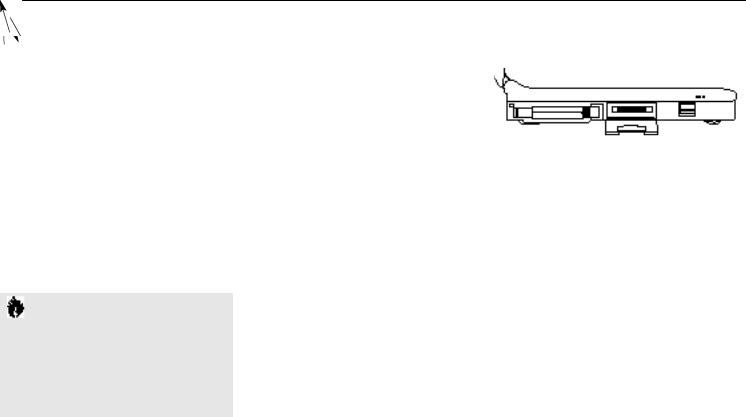
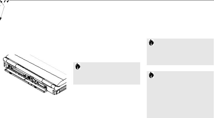
REAR PANEL COMPONENTS
RJ-11 Jack
This is the jack for attaching a telephone line to the internal modem. This jack can be used with the sliding panel in the connector cover slightly opened and the cover closed for added convenience. (Figure 1-10.)
RJ-11 Jack
External
Monitor Port
Sliding Panel
Docking Port
USB Port
Parallel
Port Connector
Cover
Figure 1-10 LifeBook™ 500 Series Rear Panel
Docking Port
This port is for connection to an optional port replicator or docking station. The connector cover must be closed and the sliding panel opened all the way when connecting a port replicator or docking station. (Figure 1-10.)
Universal Serial Bus (USB) Port
This connector allows you to connect USB devices, such as external game pads, pointing devices, keyboards and speakers. (Figure 1-10.)
C A U T I O N
Due to ongoing changes in USB technology and standards, not all USB devices and/or drivers are guaranteed to work.
External Monitor Port
This port allows you to connect an external VGA,SVGA or XGA CRT monitor.
(Figure 1-10.)
Parallel Port
The parallel port allows you to connect parallel devices, such as a parallel printer to your notebook. This is sometimes known as an LPT port.
(Figure 1-10.)
C A U T I O N
The cover – which closes over the connectors on the rear of your notebook – can be damaged if it is left open when your notebook is moved around.
C A U T I O N
The internal modem is not intended for use with Digital PBX systems. Do not connect the internal modem to a digital PBX as it may cause serious damage to the internal modem or your entire notebook. Consult your PBX manufacturer's documentation for details. Some hotels have Digital PBX systems. Be sure to find out BEFORE you connect your modem.
8
Tilt |
Docking Port |
Adjustment |
and RJ-11 Jack |
Foot |
Slide Cover |
|
Configuration |
|
Label |
Memory
Upgrade
Compartment
Docking
Recepticals
Multi-function Bay
Tilt
Adjustment
Rear Foot
Connector
Cover
Hard Drive
Compartment
Main Battery
Compartment
Figure 1-11 LifeBook 500 Series Bottom
S e t t i n g U p Y o u r L i f e B o o k 5 0 0 S e r i e s
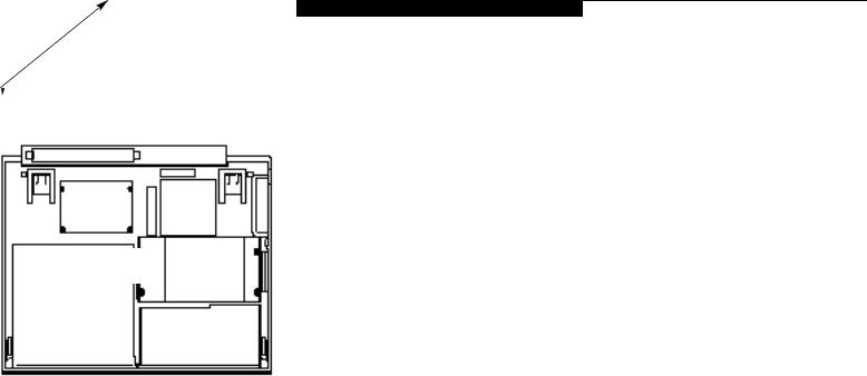
BOTTOM COMPONENTS
Tilt Adjustment Feet
These are a pair of feet which flip down and hold the back of the keyboard approximately
6° higher than the front when resting on a flat surface. They are designed to make using your notebook keyboard more comfortable.
(Figure 1-11.)
Main Unit Label
This label has the model number, serial number and other information about your notebook.
(Figure 1-11.)
Configuration Label
This label has manufacturer information that you will need to give your support representative so that he or she can help you. It exactly identifies the version of various component parts of your notebook. (Figure 1-11.)
L i f e B o o k ™ 5 0 0 S e r i e s f r o m F u j i t s u ™
Memory Upgrade Compartment
This compartment houses the memory module which allows you to expand the system memory capacity of your notebook. (See pages 106–108 for more information on installing added memory capacity.) (Figure 1-11.)
Internal Hard Drive Compartment
This compartment houses the internal hard drive. It should only be accessed for maintenance by an authorized maintenance provider.
(Figure 1-11.)
Battery Compartment
This compartment houses the main Lithium ion battery. (Figure 1-11.)
Multi-Function Bay
This compartment is accessed from the front of your notebook. (See page 5 and Figure 1-7)
9
S e c t i o n O n e
Power Indicator
Notebook Connector |
LED |
|
|
MIDI/Joystick |
|
Port |
|
S-Video |
Serial Port |
Jack |
Infrared Port |
Notebook
Connector
External Floppy Disk Drive
NTSC/PAL Adapter Port
Jack
Figure 1-12 MediaConnect Ports
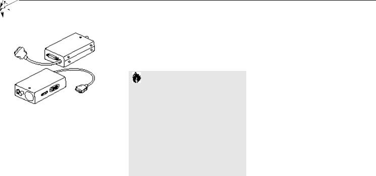
MEDIACONNECT
S-Video Jack
This jack allows you to connect,and use directly, any S-Video device, such as a VCR or TV. (The S-Video standard provides for a higher quality picture than NTSC or PAL.) (Figure 1-12.)
NTSC/PAL Jack
This connector allows you to connect,and
use directly, any TV which meets the American TV standard (NTSC) or the European TV standard (PAL). (Figure 1-12.)
C A U T I O N
NTSC and S-Video TV outputs only operate in 640 x 480 resolution mode. PAL TV outputs only operate in 800 x 600 resolution mode. TV modes are disabled until the resolution is set properly. Access to resolution settings is via the Windows® 95 Control Panel, Display, then Settings. If different resolutions are set for the built-in display and an external monitor the resolution for both will be set to that of the built-in display whenever your notebook is restarted.
Infrared Port
The fast IrDA 1.1-compatible communication port allows you to communicate with another IrDA compatible device without a cable.
(See pages 46–47 for more information.) (Figure 1-12.)
External Floppy Disk Drive Port
A connector for attaching an external floppy disk drive adapter. The adapter allows you to use your modular floppy disk drive when the Multifunction bay is being used for another purpose.
(Figure 1-12.)
Serial Port
The serial port allows you to connect serial RS-232C devices, such as serial printers or serial scanners. (Figure 1-12.)
MIDI/Joystick Port (MPU-401)
The MIDI/joystick port allows you to connect and use MIDI and game devices to your notebook. See your MIDI or game documentation for information on their installation and use.
(Figure 1-12.)
10
Notebook Connector
A connector for attaching the MediaConnect to the MediaConnect port on the left side of your notebook. (Figure 1-12.)
Power Indicator LED
This LED is On when the MediaConnect is properly attached to your notebook and your notebook is turned on. (Figure 1-12.)
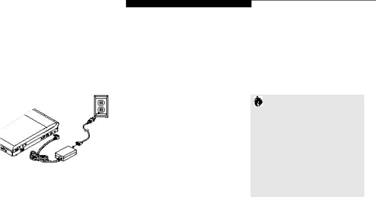
Figure 1-13 Connecting the AC Adapter
S e t t i n g U p Y o u r L i f e B o o k 5 0 0 S e r i e s
POWER SOURCES
Your notebook has four possible power sources: the main Lithium ion battery; the optional second Lithium ion battery; the AC adapter;
or the optional auto/airline adapter.
Connecting the Power Adapters
The AC adapter or the auto adapter provides power for operating your notebook and charging the batteries. (Figure 1-13.)
To Connect the AC Adapter
1.Plug the DC Output cable of the AC adapter into the DC Power jack on the right side panel of your notebook.
2.Plug the AC adapter into an AC electrical outlet.
To Connect the Optional Auto/Airline Adapter
1.Plug the DC Output cable into the DC Power port on the right side panel of your notebook
2.Plug the auto/airline adapter plug into the cigarette lighter of a car or other vehicle with
L i f e B o o k ™ 5 0 0 S e r i e s f r o m F u j i t s u ™
the ignition key in the On or the Accessories position, or the DC power jack on the airplane seat.
To Switch From AC Adapter Power
To Battery Power
1.Be sure that you have at least one charged battery installed.
2.Remove the AC adapter.
C A U T I O N
The main Lithium ion battery is not charged when you purchase your notebook. Initially you will need to connect the AC adapter or the auto adapter to use it. If you purchase a second Lithium ion battery it will not be charged when you get it. You will need to charge it prior to use. It can take up to 3 hours to charge a battery if your notebook is Off or in Suspend mode. If your notebook is in use it can take up to 9 hours or more to charge a single battery.
11

S e c t i o n O n e
DATA SECURITY
Your LifeBook™ 500 Series has a built-in hardware control password security feature that allows you to protect the data stored in your notebook from unauthorized access. Your operating system
and some applications have software control password security features that allows you to protect all or portions of the data stored in your notebook from unauthorized access.
Hardware Data Security Features
When you are using your notebook built-in hardware control password to gain access to your notebook the actual password will not appear on the screen. This is a safety precaution. The hardware control security parameters are set from the BIOS setup utility. (See Security Menu on pages 75–76 for more information on setting and clearing passwords and enabling and disabling built-in security features.)
Software Data Security Features
The operating system and some applications have security features that are independent of the built-in hardware protection features that are controlled from the BIOS. See your software documentation for more information about these features.
C A U T I O N
Make sure you memorize your passwords, both hardware and software. If you forget, you may not be able to use your notebook, and you will have to contact your service provider and
arrange to have them reset the hardware system password. See your software manuals for what to do if you forget your software security password(s).
C A U T I O N
Software security feature passwords may not be the same as the hardware security passwords. Be sure you know which features are controlled from software and which from hardware or you may lock yourself out of your own data or lock up your hardware and not be able to operate your notebook.
12

STARTING YOUR NOTEBOOK FOR THE FIRST TIME
Booting the System
The first time that you turn on your notebook you will need to attach your AC adapter because the battery is not charged when you get your machine. We strongly recommend that you not attach any other external devices and do not put any CD or floppy disk in your drives until you have gone through the initial p ower on sequence.
When you turn on your notebook for the first time it will display a Fujitsu logo on the screen. If you do nothing the system will read the hard drive for the operating system software, flash the notebook configuration information on the screen, and then the Windows® 95 Setup Wizard Screen will appear. (See Power On on page 23 for additional help.) You will then be stepped through the condition of use process. You
must complete this initial process before you will be able to use your notebook. (If you wish to access the BIOSsetup utility before you go through the condition of use process you must
L i f e B o o k ™ 5 0 0 S e r i e s f r o m F u j i t s u ™
S e t t i n g U p Y o u r L i f e B o o k 5 0 0 S e r i e s
press the Esc key followed by the F2 key while the Fujitsu Logo is still visible.) If you turn off the power without using the on screen Cancel button you will get an error message when you start your notebook again.
Conditions of Use Process
The first time you start your notebook you must confirm your acceptance of the copyright limitations for your pre-installed software. After you complete the condition of use process these screens will not appear again. There are 6 screens to read carefully and respond to.
You cannot use your notebook until this condition of use process is completed. The bottom of each screen has a <Back button, a Next>
Button and a Cancel button which are activated by the integrated touchpad cursor control and button click. The <Back button will return
you to the previous screen. The Next> button activates any choices or information you have entered and takes you on to the next screen.
The Cancel button allows you to stop the setup process.
If you stop the process your notebook will start up at the beginning of the Windows 95 Setup Wizard.
The screens you will be required to respond to are described with the required action.
User Information
Fill in your name and your company name as you want the software licensed. To step from the name blank to the company blank press the Tab key. When the information has bee entered click on the Next> button. You will not be allowed to continue until you make an entry.
License Agreement
Read the agreement carefully. You can scroll through the text using the integrated touchpad pointing device to activate the scroll bar or use the up arrow’ and down arrow ‘ keys to move up and down the text one line at a time, or use the Page Up and Page Down keys to move the text one screen at a time. When you
finish reading you must point and click to accept or reject the terms of the agreement and then click on the Next> button.
13

S e c t i o n O n e
P O I N T
If you reject the terms of the license agreement you will be asked to review the license agreement for information on returning Windows® 95 or to shutdown your notebook.
Certificate of Authenticity
Look in the box that your notebook came in and you will find a Windows 95 Certificate of Authenticity and a Windows 95 Users manual. On the certificate and also on the ba ck of the manual you will find a bar-code with a number above it. These numbers should be the same, they are your product code and the number you should enter on the Certificate of Authenticity screen. When you have entered the number exactly as shown then click on the Next> button.
Start Wizard
The Start Wizard screen will appear if you have entered a valid product code. When you click on the Finish button the display will flash various screens as the system identifies what hardware is installed and runs a virus check.
Time Zone
When your notebook has completed identifying all of the installed hardware it will display a dialog box for entering which time zone you wish to set in the clock.
Windows Messaging
Once you have selected a time zone you will see a screen announcing that Windows messaging is being set up.
Printer Setup
When the messaging set up is complete a dialog box will appear for selecting which printer is to be attached to your notebook. You do not have to select a printer at this time. If you do not wish to select a printer, click on the Cancel button. If you do wish to sele ct a printer click on the Next button and answer the questions.
C A U T I O N
If you have a LifeBook™ 565Tx you must click on the Click on Me First icon to complete the startup, read the screen which appears, hit any key and then restart your notebook from the Start menu. You are now ready for normal operation. If you fail to do this some of your pre-installed application software may not operate correctly.
P O I N T
You will find a Recovery CD-ROM packet in your accessories box. Please store the packet in a safe place in case there is a loss of data and it becomes necessary to re-install your operating system and and/or application programs. (See Restoring Your Pre-installed Software from the Recovery CD-ROM on page 138.)
14

Welcome to Windows® 95
Once you have completed the printer setup or chosen not to set up a p rinter at this time you will see the Welcome screen for Windows 95.
You can choose: Windows Tour ; What’s
New ; Online Registration; or Close . You are now in the Windows 95 operating system and the Condition of Use process will not be repeated.
L i f e B o o k ™ 5 0 0 S e r i e s f r o m F u j i t s u ™
S e t t i n g U p Y o u r L i f e B o o k 5 0 0 S e r i e s
USER REGISTRATION
There are three ways to register your notebook.
1.The registration card provided in the box with your LifeBook 500 Series which can be filled out and mailed.
2.A registration form in the Fujitsu Welcome Center which can be filled out on your notebook and sent in a variety of ways,including printing and mailing, faxing or e-mailing.
3.Telephone registration by calling the Fujitsu PC service and support line at 1-800-8FUJITSU (1-800-838-5487).
LEARNING ABOUT YOUR
OPERATING SYSTEM AND
APPLICATION SOFTWARE
Tutorials
All operating systems and most application software have tutorials built-in. We highly recommend that you step through your tutorial before you use an application even if you are familiar with the same application on a different machine,an earlier version of the application, or with a similar product.
Manuals
In the accessories box you will find manuals for Windows 95 and other pre-installed software.
Software manuals of pre-installed software that are not in the accessories box are available online. See the help screens of your pre-installed software. We recommend that you review these manuals for general information on the use
of these applications and to get a basic understanding of what is covered in the manual, and how it is organized,should questions arise as you use the applications.
15

S e c t i o n T w o
Using Your LifeBook™ 500 Series from Fujitsu™
Built-in Display . . . . . . . . . . . . |
. . |
. |
. |
18 |
Adjusting the Keyboard Angle . . . . |
. . |
. |
. |
18 |
Status Indicator Panel. . . . . . . . . |
. . |
. |
. |
19 |
Power On . . . . . . . . . . . . . . |
. . |
. |
. |
23 |
Power Off . . . . . . . . . . . . . . |
. . |
. |
. |
24 |
Restarting the System . . . . . . . . |
. . |
. |
. |
25 |
Fujitsu Welcome Center . . . . . . . |
. . |
. |
. |
25 |
Batteries . . . . . . . . . . . . . . . |
. . |
. |
. |
25 |
Integrated Touchpad Pointing Device. |
. . |
. |
. |
29 |
Using the Keyboard. . . . . . . . . . |
. . |
. |
. |
32 |
Using the Volume Control . . . . . . |
. . |
. |
. |
33 |
Floppy Disk Drive . . . . . . . . . . . |
. . |
. |
. |
34 |
CD-ROM Drive . . . . . . . . . . . . |
. . |
. |
. |
37 |
Hard Drive . . . . . . . . . . . . . . |
. . |
. |
. |
38 |
Power Management . . . . . . . . . |
. . |
. |
. |
39 |
Internal Modem . . . . . . . . . . . |
. . |
. |
. |
46 |
Infrared Port . . . . . . . . . . . . . |
. . |
. |
. |
46 |
Pre-Installed Software . . . . . . . . |
. . |
. |
. |
47 |
 Loading...