


734A
Table of contents
 Loading...
®
732B/734A
DC Reference Standard
Instruction Manual
PN 869321
March 1992 Rev.3, 11/97
© 1993, 1994, 1997 Fluke Corporation, All rights reserved. Printed in U.S.A.
All product names are trademarks of their respective companies.

LIMITED WARRANTY & LIMITATI O N OF LIABILITY
Each Fluke product is warranted to be free from defects in material and workmanship under
normal use and service. The warranty period is one year and begins on the date of shipment.
Parts, product repairs and services are warranted for 90 days. This warranty extends only to the
original buyer or end-user customer of a Fluke authorized reseller, and does not apply to fuses,
disposable batteries or to any product which, in Fluke’s opinion, has been misused, altered,
neglected or damaged by accident or abnormal conditions of operation or handling. Fluke
warrants that software will operate substantially in accordance with its functional specifications for
90 days and that it has been properly recorded on non-defective media. Fluke does not warrant
that software will be error free or operate without interruption.
Fluke authorized resellers shall extend this warranty on new and unused products to end-user
customers only but have no authority to extend a greater or different warranty on behalf of Fluke.
Warranty support is available if product is purchased through a Fluke authorized sales outlet or
Buyer has paid the applicable international price. Fluke reserves the right to invoice Buyer for
importation costs of repair/replacement parts when product purchased in one country is submitted
for repair in another country.
Fluke’s warranty obligation is limited, at Fluke’s option, to refund of the purchase price, free of
charge repair, or replacement of a defective product which is returned to a Fluke authorized
service center within the warranty period.
To obtain warranty service, contact your nearest Fluke authorized service center or send the
product, with a description of the difficulty, postage and insurance prepaid (FOB Destination), to
the nearest Fluke authorized service center. Fluke assumes no risk for damage in transit.
Following warranty repair, the product will be returned to Buyer, transportation prepaid (FOB
Destination). If Fluke determines that the failure was caused by misuse, alteration, accident or
abnormal condition of operation or handling, Fluke will provide an estimate of repair costs and
obtain authorization before commencing the work. Following repair, the product will be returned to
the Buyer transportation prepaid and the Buyer will be billed for the repair and return
transportation charges (FOB Shipping Point).
THIS WARRANTY IS BUYER’S SOLE AND EXCLUSIVE REMEDY AND IS IN LIEU OF ALL
OTHER WARRANTIES, EXPRESS OR IMPLIED, INCLUDING BUT NOT LIMITED TO ANY
IMPLIED WARRANTY OF MERCHANTABILITY OR FITNESS FOR A PARTICULAR PURPOSE.
FLUKE SHALL NOT BE LIABLE FOR ANY SPECIAL, INDIRECT, INCIDENTAL OR
CONSEQUENTIAL DAMAGES OR LOSSES, INCLUDING LOSS OF DATA, WHETHER
ARISING FROM BREACH OF WARRANTY OR BASED ON CONTRACT, TORT, RELIANCE OR
ANY OTHER THEORY.
Since some countries or states do not allow limitation of the term of an implied warranty, or
exclusion or limitation of incidental or consequential damages, the limitations and exclusions of
this warranty may not apply to every buyer. If any provision of this Warranty is held invalid or
unenforceable by a court of competent jurisdiction, such holding will not affect the validity or
enforceability of any other provision.
Fluke Corporation Fluke Europe B.V.
P.O. Box 9090 P.O. Box 1186
Everett, WA 98206-9090 5602 BD Eindhoven
U.S.A. The Netherlands
5/94

Declaration of the Manufacturer or Importer
We hereby certify that the Fluke Models 732B and 734A are in compliance with BMPT Vfg
243/1991 and is RFI suppressed. The normal operation of some equipment (e.g. signal
generators) may be subject to specific restrictions. Please observe the notices in the users
manual. The marketing and sales of the equipment was reported to the Central Office for
Telecommunication Permits (BZT). The right to retest this equipment to verify compliance with the
regulation was given to the BZT.
Bescheinigung des Herstellers/Importeurs
Hiermit wird bescheinigt, da
β
Fluke Models 732B und 734A in Übereinstimmung mit den
Bestimmungen der BMPT-AmtsblVfg 243/1991 funk-entstört ist. Der vorschriftsmäßige Betrieb
mancher Geräte (z.B. Meßsender) kann allerdings gewissen Einschränkungen unterliegen.
Beachten Sie deshalb die Hinweise in der Bedienungsanleitung. Dem Bundesamt für Zulassungen
in der Telekcommunikation wurde das Inverkehrbringen dieses Gerätes angezeigt und die
Berechtigung zur Überprüfung der Serie auf Einhaltung der Bestimmungen eingeräumt.
Fluke Corporation
Electromagnetic Compatibility
This instrument is designed to operate in Standards Laboratory environments where the radio
frequency (RF) environments is highly controlled. If used in areas of high RF, there could be errors
in measurements.


Safety Summary
Safety Terms in this Manual
Instrument models described in this manual (Models 732B and 734A) have been designed
and tested in accordance with IEC Publication 348, Safety Requirements for Electronic
Measuring Apparatus. This Instruction Manual contains information, warnings, and cautions
that must be followed to ensure safe operation and to maintain the instrument in a safe
condition. Use of these instruments in a manner mot specified herein may impair the
protection by the instrument.
Warning statements identify conditions or practices that could result in personal injury or
loss of life.
Caution statements identify conditions or practices that could result in damage to the
equipment.
Symbols Marked on Equipment
Power Off Switch Position
Power On Switch Position
Ground (Earth) Terminal
Attention — refer to the manual. This symbol indicates that
information about the use of a feature is contained in the manua
l.
Power Source
The instruments are intended to operate from a power source that will not apply more
than 264V ac rms between the supply conductors or between either supply conductor and
ground. A protective ground connection by way of the grounding conductor in the power
cord is essential for safe operation.
Use the Proper Fuse
To avoid fire hazard, use only a fuse identical in type, voltage rating, and current rating
as specified on the rear panel fuse rating label. Never bypass a fuse by shorting across
the fuse terminals.
Grounding the Standard
These are Safety Class I (grounded enclosure) instruments as defined in IEC 348. To
avoid electrical shock, plug the power cord into a properly wired earth grounded
receptacle, or ground the GROUND binding post befor e connecting anything to any of
the instrument binding posts. A protective ground connection by way of the grounding
conductor in the power cord is essential for safe operation when using ac line power.
Use the Proper Power Cord
Use only the power cord and connector appropriate for the voltage and plug
configuration in your country.
Use only a power cord that is in good condition.
Refer cord and connector changes to qualified service personnel.

Do Not Operate in Explosive Atmospheres
To avoid explosion, do not operate the instrument in an atmosphere of explosive gas.
Do Not Attempt to Operate if Protection May be Impaired
If the instrument appears damaged or operates abnormally, protection may be impaired.
Do not attempt to operate it. When is doubt, have the instrument serviced.
Use Care When Servicing with Power On
High voltages exist at several points inside the instrument. To avoid personal injury, do
not touch exposed connections and components while power is on. Disconnect line cord
and battery power before removing protective panels, soldering, or replacing
components.

i
Table of Contents
Chapter Title Page
1 Introduction and Specifications.......................................................... 1-1
1-1. Introduction ........................................................................................... 1-3
1-2. Hardware Options .................................................................................. 1-4
1-3. 734A-7001 Instrument Enclosure ..................................................... 1-4
1-4. 723B-7001 External Battery and Charger ......................................... 1-4
1-5. Accessory Y734 Rack Mount Kit ..................................................... 1-4
1-6. Calibration Options ............................................................................... 1-5
1-7. 732B-000 Special Calibration ........................................................... 1-5
1-8. 732B-100 Special Calibration and Drift Characterization ................ 1-5
1-9. 732B-200 On-Site Calibration .......................................................... 1-5
1-10. Warranty Information ............................................................................ 1-5
1-11. Service and Reshipment Information .................................................... 1-6
1-12. Specifications ........................................................................................ 1-6
2 Installation............................................................................................ 2-1
2-1. Introduction ........................................................................................... 2-3
2-2. Unpacking and Inspection ..................................................................... 2-3
2-3. Selecting Line Voltage and Accessing the Fuse ................................... 2-4
2-4. Connecting to Line Power ..................................................................... 2-5
2-5. Installing a 732B or 732B-7001 in a 734A-7001 Instrument Enclosure 2-5
3 Operation.............................................................................................. 3-1
3-1. Introduction ........................................................................................... 3-3
3-2. Summary of the Features ....................................................................... 3-3
3-3. 732B DC Standard Front Panel ......................................................... 3-3
3-4. 732B DC Standard Rear Panel .......................................................... 3-3
3-5. 732B-7001 External Battery and Charger Front Panel ..................... 3-3
3-6. 732B-7001 External Battery and Charger Rear Panel ...................... 3-3
3-7. 734A-7001 Instrument Enclosure Front Panel ................................. 3-3
3-8. 734A-7001 Instrument Enclosure Rear Panel .................................. 3-3
3-9. Powering the Standard .......................................................................... 3-11
3-10. Setting the BAT Switch .................................................................... 3-12
3-11. Charging the Internal Battery ........................................................... 3-12

732B/734A
Instruction Manual
ii
3-12. Powering the Standard from a 732B-7001 ........................................ 3-12
3-13. Replacing the Internal Battery .......................................................... 3-13
3-14. Connecting Cables to the Output .......................................................... 3-14
3-15. Connecting the GUARD and GROUND .......................................... 3-15
3-16. Monitoring Oven Temperature .............................................................. 3-16
3-17. Resetting the IN CAL Indicator ............................................................ 3-16
3-18. Monitoring The IN CAL Indicator State Remotely .............................. 3-16
3-19. Monitoring Long-Term Stability ........................................................... 3-17
3-20. Minimizing Error Sources ..................................................................... 3-18
3-21. Mechanically Induced Errors ............................................................ 3-18
3-22. Thermal EMFs .................................................................................. 3-18
3-23. Output Cable Loading ....................................................................... 3-18
4 Theory of Operation............................................................................. 4-1
4-1. Introduction ........................................................................................... 4-3
4-2. Overall Functional Description ............................................................. 4-3
4-3. Model 734A Functional Description ................................................ 4-5
4-4. Model 732B-7001 External Battery/Power Supply .......................... 4-5
4-5. 732B Circuit Description ...................................................................... 4-5
4-6. 10V Reference Circuit ...................................................................... 4-5
4-7. Generating the 1.018V Output ...................................................... 4-7
4-8. Biasing the Refamp for Low Temperature Coefficient ................ 4-7
4-9. Sense Current Cancellation .......................................................... 4-7
4-10. Buffering of the 10V Output ........................................................ 4-8
4-11. Oven Temperature Controller A4 ..................................................... 4-8
4-12. A1 Front Panel Assembly ................................................................. 4-8
4-13. Power Supplies and Battery Charger Assembly A5 ......................... 4-9
4-14. Overvoltage Protection Circuitry ................................................. 4-9
4-15. Raw DC Power Supply ................................................................. 4-11
4-16. Battery Charger ............................................................................. 4-11
4-17. +11.5V Preregulator ..................................................................... 4-11
4-18. +11.5V Low-Dropout Regulator .................................................. 4-12
4-19. -6V Power Supply ......................................................................... 4-12
4-20. IN CAL Logic ............................................................................... 4-12
4-21. LED Drive Logic .......................................................................... 4-12
4-22. AC Power to Battery Power Switching Circuitry ......................... 4-13
4-23. Battery Circuit .............................................................................. 4-13
4-24. Rear Panel Connections ................................................................ 4-13
4-25. Low-Battery Shutdown Circuitry ................................................. 4-14
5 Maintenance......................................................................................... 5-1
5-1. Introduction ........................................................................................... 5-3
5-2. Service Information ............................................................................... 5-3
5-3. Replacing the Fuse ................................................................................ 5-3
5-4. Cleaning the External Surfaces ............................................................. 5-3
5-5. Calibration ............................................................................................. 5-3
5-6. Preparing for Calibration .................................................................. 5-4
5-7. Preparing for 10V Calibration with Adjustment ............................... 5-4
5-8. Calibration with Adjustment ............................................................. 5-6
5-9. Calibration Without Adjustment ....................................................... 5-8
5-10. Access Procedures ................................................................................. 5-9
5-11. Initial Access Procedure ................................................................... 5-9
5-12. Replacing the Battery ........................................................................ 5-9
5-13. Replacing the Oven Assembly .......................................................... 5-13

Contents
(continued)
iii
5-14. Accessing the A5 Battery Charger .................................................... 5-13
5-15. Removing the Power Transformer Assembly ................................... 5-13
5-16. Troubleshooting .................................................................................... 5-14
5-17. 10V Reference Performance Test ..................................................... 5-14
5-18. Troubleshooting the A5 Battery Charger Assembly ......................... 5-14
5-19. Transformer/Rectifier/Filter ......................................................... 5-15
5-20. Battery Charger ............................................................................. 5-15
5-21. +11.5V DC Preregulator ............................................................... 5-15
5-22. +11.5V DC Regulator ................................................................... 5-16
5-23. -6V DC Supply ............................................................................. 5-16
5-24. IN CAL LED Logic ...................................................................... 5-16
6 List of Replaceable Parts .................................................................... 6-1
6-1. Introduction ........................................................................................... 6-3
6-2. How to Obtain Parts .............................................................................. 6-3
6-3. Manual Status Information .................................................................... 6-3
6-4. Newer Instruments ................................................................................ 6-3
6-5. Service Centers ..................................................................................... 6-4
6-6. Parts ....................................................................................................... 6-4
7 Schematic Diagrams............................................................................ 7-1
A1 Front Panel PCA............................................................................................ 7-3
A2 Flex Circuit PCA........................................................................................... 7-5
A3 BCD Switch PCA.......................................................................................... 7-6
A4 Oven Control PCA......................................................................................... 7-7
A5 Power Supply PCA........................................................................................ 7-8
Index

732B/734A
Instruction Manual
iv

v
List of Tables
Table Title Page
2-1. Standard Equipment................................................................................................. 2-3
2-2. AC Line Cords Available for Fluke Instruments..................................................... 2-3
3-1. 732B DC Standard Front Panel Features................................................................. 3-5
3-2. 732B DC Standard Rear Panel Features.................................................................. 3-7
3-3. 732B-7001 External Battery/Charger Front Panel Features.................................... 3-8
3-4. 732B-7001 External Battery/Charger Rear Panel Features..................................... 3-9
3-5. 734A-7001 Instrument Enclosure Front Panel Features ......................................... 3-10
3-6. 734A-7001 Instrument Enclosure Rear Panel Features........................................... 3-11
5-1. Equipment Required for Calibration ....................................................................... 5-4
6-1. 734A DC Reference Standard ................................................................................. 6-4
6-2. 732B DC Standard................................................................................................... 6-8
6-3. A1 Front Panel PCA................................................................................................ 6-15
6-4. A5 Power Supply PCA............................................................................................ 6-17

732B/734A
Instruction Manual
vi

vii
List of Figures
Figure Title Page
1-1. Mechanical Specifications....................................................................................... 1-11
2-1. Line Power Cords Available for Fluke Instruments................................................ 2-4
2-2. Line Power Label and Fuse Location...................................................................... 2-7
2-3. Installing a 732B or 732B-7001 in a 734A-7001 Instrument Enclosure................. 2-8
3-1. 732B DC Standard Front Panel Features................................................................. 3-4
3-2. 732B DC Standard Rear Panel Features.................................................................. 3-6
3-3. 732B-7001 External Battery/Charger Front Panel Features.................................... 3-8
3-4. 732B-7001 External Battery/Charger Rear Panel Features..................................... 3-9
3-5. 734A-7001 Instrument Enclosure Front Panel Features ......................................... 3-10
3-6. 734A-7001 Instrument Enclosure Rear Panel Features........................................... 3-11
3-7. 732B MONITOR/EXT BAT IN Connector Pinout................................................. 3-13
3-8. 732B-7001 BAT OUT Connector Pinout................................................................ 3-14
3-9. Typical 732B Cable Connections............................................................................ 3-15
3-10. IN CAL Status Output Circuit................................................................................. 3-17
3-11. Loading Error Example ........................................................................................... 3-19
4-1. 732B Overall Block Diagram.................................................................................. 4-4
4-2. 10V Reference Circuit Block Diagram ................................................................... 4-6
4-3. A5 Power Supply/Battery Charger Block Diagram ................................................ 4-10
5-1. 10V Output Calibration Connections ...................................................................... 5-5
5-2. Location of 732B Calibration Adjustment Switches............................................... 5-7
5-3. Accessing Internal Components.............................................................................. 5-10
5-4. Replacing the Battery .............................................................................................. 5-12
6-1. 734A DC Reference Standard ................................................................................. 6-5
6-2. 732B DC Standard................................................................................................... 6-10
6-3. A1 Front Panel PCA................................................................................................ 6-16
6-4. A5 Power Supply PCA............................................................................................ 6-20

732B/734A
Instruction Manual
viii

1-1
Chapter 1
Introduction and Specifications
Title Page
1-1. Introduction............................................................................................ 1-3
1-2. Hardware Options................................................................................... 1-4
1-3. 734A-7001 Instrument Enclosure...................................................... 1-4
1-4. 723B-7001 External Battery and Charger.......................................... 1-4
1-5. Accessory Y734 Rack Mount Kit ...................................................... 1-4
1-6. Calibration Options................................................................................ 1-5
1-7. 732B-000 Special Calibration............................................................ 1-5
1-8. 732B-100 Special Calibration and Drift Characterization................. 1-5
1-9. 732B-200 On-Site Calibration ........................................................... 1-5
1-10. Warranty Information............................................................................. 1-5
1-11. Service and Reshipment Information..................................................... 1-6
1-12. Specifications......................................................................................... 1-6

732B/734A
Instruction Manual
1-2

Introduction and Specifications
Introduction
1
1-3
Introduction 1-1.
Caution
Set the rear panel BAT switch to ✡ (on) before connecting AC
power. This is required for proper instrument operation. If your
732B was shipped cold, you will need to calibrate it against a
traceable standard as described in Section 5 before you begi n
using it. For best results, leave the standard powered for a
minimum of 14 days before you calibrate and begin using it.
Model 732B is a dc voltage laboratory standard that produces reference voltages of 10V
and 1.018V. Model 734A contains four 732B DC Standards in a chassis. The 732B is
highly stable, rugged and transportable. Its 10V output excels in stability, and can be
used as your direct link in the traceability chain to national standards. You can use the
732B 1.018V output to transfer the "volt" at the 1.018V level from one set of saturated
standard cells to another. You can also use the 1.018V output as a working standard with
older equipment that requires a standard cell voltage input.
The 10V output’s long-term stability, predictable drift rate, low uncertainty, convenient
level, and immunity to accidental damage make the 732B or 734A the preferred artifact
for maintaining a local standard of voltage. With time characterization (Calibration
Option 732B-100) the drift rate for the 10V output is given. This reduces the 10V output
uncertainty from 2 ppm/year to 1 ppm/year.
All outputs of the 732B can withstand short circuit indefinitely, without damage to the
instrument or disruption of the state of calibration. Recovery time for a momentary short
is less than 2 minutes; for an extended short, recovery time is less than 2 hours.
To maintain calibration as a traceable standard, the 732B must continue to receive
uninterrupted operating voltage from ac line power or from the internal battery. If
battery voltage drops too low, the front panel IN CAL indicator goes out and
recalibration is required.
The internal rechargeable battery (if switched on) protects the standard from line power
interruption and provides power for hot shipment (shipment under power). The 732B
outputs are unaffected as you change between battery or ac line power. Battery operation
with a fully charged battery lasts at least 72 hours. You can extend battery operation by
connecting an external 12V battery such as Model 732B-7001 to the rear panel
MONITOR/EXT BAT IN connector. Plugging the 732B into ac line power for 24 hours
fully recharges the internal battery.
Four front panel indicators show operating status. Model 732B-7001 External Battery
and Charger has all but the IN CAL indicator.
• AC PWR lights when the 732B is connected to ac line power.
• IN CAL goes out to warn you when the 732B may have lost its calibration. This
indicator responds to an excessively large drop in battery voltage or a large change
in oven temperature. If battery voltage falls below the level needed to keep the 732B
working normally, the IN CAL indicator extinguishes, indicating a loss of the state
of calibration. Once power is restored and the output has been verified, you can reset
the IN CAL indicator.
Note
An illuminated IN CAL indicator is not sufficient by itself to indicate the
732B satisfies the specifications of section 1-12. See Calibration label on
front of the 732B for calibration due date.
732B/734A
Instruction Manual
1-4
• LOW BAT blinks to warn you to plug the line cord into ac power when only a few
hours of battery operation remain.
• CHARGE lights when the battery is being recharged in constant-current charge
mode, and is off when the battery is charged to the 90% level. At 90% of full charge,
a float charge completes and maintains full charge.
You can monitor the oven temperature by measuring the resistance of the oven
temperature thermistor through the rear panel MONITOR/EXT BAT IN connector.
Instructions for using this connector are in Section 3.
Hardware Options 1-2.
Table 1-1 summarizes hardware options for the 732B DC Standard. Calibration Options
are described further on in this section.
Table 1-1. 732B/734A Hardware Options and Accessories
Model Number Name
734A-7001 Instrument Enclosure
732B-7001 External Battery and Charger
732B-7002 Transit Case for two 732Bs or 732B-7001s
Y734 Rack Mount Kit for 734A or 734A-7001
734A-7001 Instrument Enclosure 1-3.
The Model 734A DC Reference Standard is made up of one 734A-7001 Instrument
Enclosure and four 732B DC Standards. The Model 734A-7001 can be purchased
separately as needed for your application. The enclosure securely holds up to four 732B
DC Standards and/or 732B-7001 External Battery/Chargers (described next).
An ac power bus inside the 734A-7001 enclosure powers up to four 732B units with only
one ac line cord. Using the enclosure allows you to rack mount 732Bs. (See Y734 Rack
Mount Kit.)
723B-7001 External Battery and Charger 1-4.
The Model 732B-7001 External Battery and Charger is contained in the same enclosure
as the 732B. This means it fits into and is powered by the 734A-7001 Instrument
Enclosure just like a 732B DC Standard.
When the external battery is completely charged and connected to a completely charged
732B, it increases 732B battery operating time from 72 to 130 hours. Just as in the 732B,
the charger in the 732B-7001 takes 36 hours to completely charge the battery (with no
load on the battery). Refer to Section 3 for information about interconnecting 732Bs and
732B-7001s.
Accessory Y734 Rack Mount Kit 1-5.
To rack mount a 732B, use the 734A-7001 Instrument Enclosure (standard equipment
with Model 734A). Use Accessory Y734 Rack Mount Kit to mount the enclosure in a
rack. Outside dimensions of the 732B and 734A are shown in the specifications at the
end of this section. Instructions for rack mounting the 734A-7001 Instrument Enclosure
are packed with the kit.

Introduction and Specifications
Calibration Options
1
1-5
Calibration Options 1-6.
Unless requested at time of order, the 732B is shipped cold (not under battery power)
and will need to be calibrated on receipt. A procedure to calibrate a 732B using a
reference 732B as a transfer standard is provided in Section 5. After calibration, the
732B must be kept powered by ac power or battery, even during shipment. Fluke
calibration services that are available for the 732B are described next.
Note
Contact a Fluke Sales or Service Center for price and delivery information
about 732B calibration options. Addresses for Fluke Service Centers are
provided following the parts lists in Section 6.
732B-000 Special Calibration 1-7.
If you ordered Option 732B-000, the standard is shipped to you hot with a calibration
report that assigns a value to the 10V output. This calibration meets or exceeds the
requirements of MIL-STD-45662A.
732B-100 Special Calibration and Drift Characterization 1-8.
If you ordered Option 732B-100, the standard is shipped to you hot with a calibration
report that assigns a value to the 10V output. This calibration meets or exceeds the
requirements of MIL-STD-45662A. In addition, a calibration report shows the predicted
output on the 1st of each month for the 12 months following shipment.
732B-200 On-Site Calibration 1-9.
Option 732B-200 is the Fluke Direct Volt Maintenance Program, as has been applied to
other Fluke dc standards equipment. This program works as follows:
1. Fluke hot-ships a Fluke-owned transfer standard with all the necessary
interconnecting cables and clear instructions.
2. You make a series of comparisons over five days and send your data to Fluke.
3. Fluke sends you a calibration report that assigns a value to your 732B 10V output
relative to the Fluke Volt. The Fluke Volt is maintained by means of a Josephson
Junction array in the Fluke Primary Standards laboratory. Periodic transfers to NIST
also maintain traceability to the U.S. Legal Volt (at greater uncertainty) for those
who are required to maintain NIST traceability.
Warranty Information 1-10.
The warranty that applies to your Fluke product appears at the front of this manual.

732B/734A
Instruction Manual
1-6
Service and Reshipment Information 1-11.
Warning
Service procedures, including replacing the bat t eri es, are to be
done by qualified service personnel only. To avoi d el ect ric
shock or fire, do not service the 732B unless you are qualified
to do so.
If your standard ever needs service, you may return it to Fluke for Warranty or after-
warranty repair. Addresses for authorized service centers are in Section 6. If you are
qualified to troubleshoot electronic equipment, you can refer to Section 5 for theory,
troubleshooting, and calibration information. Schematic diagrams are in Section 7.
The 732B and 734A are designed to withstand the shock and vibration of air and ground
shipment, provided that you protect the equipment with a proper shipping container.
When you return a 732B or 734A to Fluke for service or calibration, use the original
shipping carton, a replacement carton obtained from Fluke, or the accessory transit case.
Transit Case Model 732B-7002 holds two 732B DC Standards or 732B-7001 External
Battery/Chargers.
Caution
Do not charge a 732B or 732B-7001 while it is in the transit
case. Doing so can cause overheating and possible equipment
damage, and in the case of the 732B, loss of the st ate of
calibration.
Specifications 1-12.
Output Voltages
10V and 1.018V are provided at separate binding post pairs with the following
characteristics:
Note
A potential difference of approximately <200
µ
V exists between the
floating 1.018V LO and 10V LO terminals. Consequently, buck
measurements cannot be made between these sources without taking this
into account.
Introduction and Specifications
Specifications
1
1-7
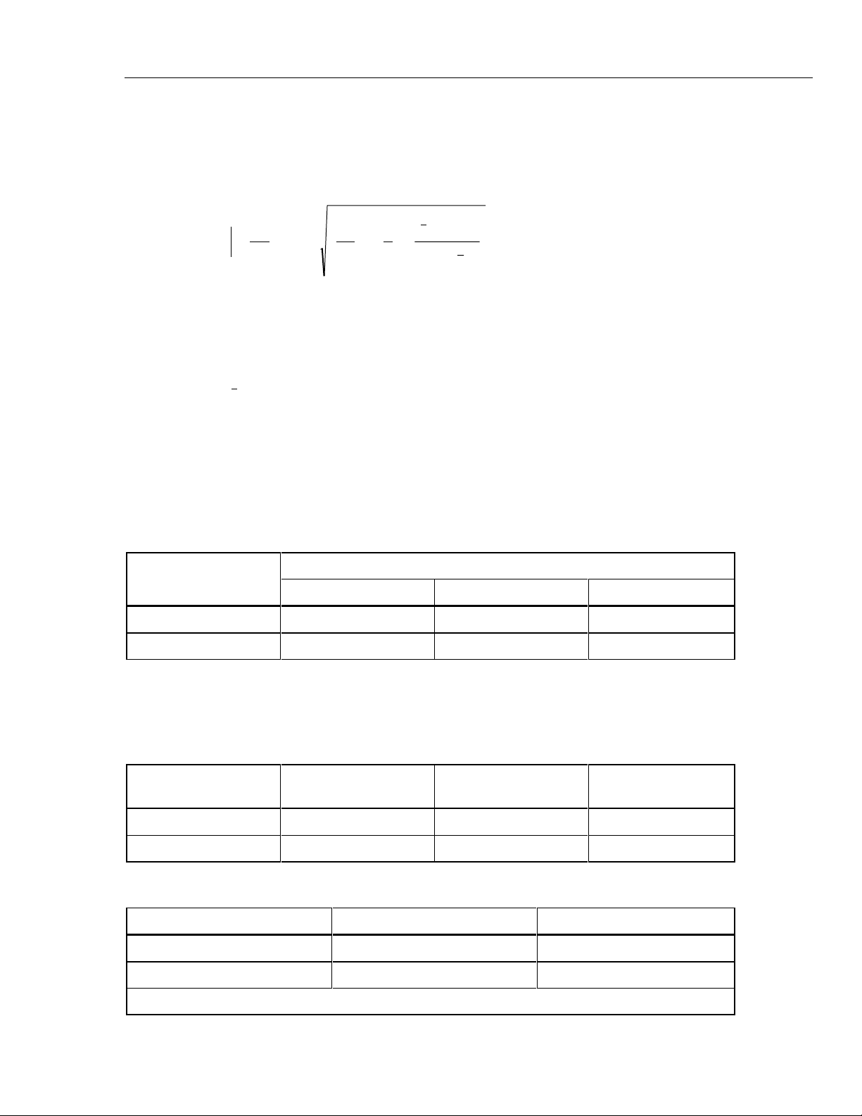
Stability
Stability for a given period of time is defined as the output uncertainty minus the
calibration uncertainty at the 99% Confidence Level. When the output voltage is
characterized by a regression model, stability is given by the following equation:
()
b
P
365
2.65S
1
S
ra
S
1
1
n
2
X
j
x
2
+
+
+
+−
−
∑
2
1
xPx
where b = slope of regression in ppm/year
S
1
= standard deviation about the regression (SDEV)
S
ra
= SDEV of data filtered with 7-day moving average filter (MAF)
P = Period of time under consideration in days
x = mean time for regession data
n = 180 period (typically 2 meassurements per day)
Xj = jth period
X
1
= time at beginning of data
Each data point for the computation of the regression parameters is the average voltage
of 50 readings taken in a 50-second measurement period.
Stability for the 732B outputs at 23 ±1°C is specified as follows:
Output Voltage
Stability (± ppm)
30 Days 90 Days 1 Year
10V 0.3 0.8 2.0
1.018V 0.8 NA NA
Noise at the Output Terminals
Output noise is specified for both day-to-day observations and for short-term
observations. The former is given by the standard deviation of a 90-day regression
model. The latter is in terms of its rms value in a bandwidth as follows:
Output Voltage S
1
(± ppm) S
ra
(± ppm)
Noise (0.01 Hz to 10
Hz (± ppm rms)
10V 0.068 0.05 0.06
1.018V 0.1 NA 0.03
Output Current and Limits
Output Voltage Output Current Limit Output Impedance
10V 12 mA (Note) ≤ 1 mΩ
1.018V 20 pA ≤ 1 kΩ
Note: Limit output current to ≤ 0.1 mA to realize 72 hour battery operation.
732B/734A
Instruction Manual
1-8
Output Adjustability
- 10V: 0.15 ppm resolution
- 1.018V: Set at nominal ±1 mV. No adjustment is provided.
The 10V adjustment is done with a set of four decade-control switches with a range of at
least 4 mV.
Retrace (Hysteresis) Error
The following table shows the change in 10V output voltage following a power outage
(with the battery turned off) with temperature held constant in the normal operating
range.
Period that Power is Turned Off Change in 10V Output Value
10 minutes or less ≤ ±0.1 ppm
10 minutes to 24 hours ≤ ±0.25 ppm
Stabilization Time Requirements
The following information specifies the warmup times required after ac line and battery
power has been turned off. The IN CAL indicator will be off, and recalibration will be
necessary. The previously specified retrace error specification can be used in the case of
brief power interruptions.
With no power interruption: No stabilization time is required after moving into
another environment.
Power off for less than 1 hour: 1-hour warmup required
Power off for 1 to 24 hours: 24-hour warmup required
Electromagnetic Compatibility
This instrument is designed to operate in Standards Laboratory environments where the
radio frequency (RF) environment is highly controlled. If used in environments with
field strengths >0.18 V/m, there could be errors in measurements.
Temperature Coefficient (TC) of Output
In the temperature range of 15°C to 35°C, the magnitude of the TC is bounded by the
following:
- 10V Output: TC ≤ 0.04 ppm/°C
- 1.018V Output: TC ≤ 0.1 ppm/°C
Load Regulation
10V Output Load Change Maximum 10V Output Change
0 mA to 12 mA (no load to full load) ±1 ppm
0 mA to 2 mA ±0.1 ppm

Introduction and Specifications
Specifications
1
1-9
Line Regulation
The outputs will change no more than 0.05 ppm for any 10% line voltage change or for
the entire operating range of the battery.
Output Protection
All outputs can be shorted indefinitely without damage to the instrument. The 10V
output can withstand voltages from other sources as follows:
1. For voltages ≤ 220V dc, the unit is protected for up to 50 mA continuous current.
2. For voltage ≤ 1100V dc, the unit is protected for up to 25 mA continuous current or
up to 0.6 joules for short periods of time.
Environment
Temperature Range Relative Humidity Altitude
Normal Operation 15°C to 35°C 15% to 80% 0 to 6,000 ft
Safe Operation 0°C to 50°C 15% to 90% 0 to 10,000 ft
Storage (With battery
removed)
-49°C to 50°C Noncondensing 0 to 40,000 ft
Compliance to Standards
ANSI/ISA-S82
CSA C22.2 #231
IEC348
IEC 1010
UL 1244
Line Power Requirements
Line voltage is accepted in the two ranges 90 to 132V and 180 to 264V, at 47 to 63 Hz as
shown in the table below. AC line current at 120V ac is 0.13A.
732B Line Voltage Setting Line Voltage Accepted Frequency Accepted
100V 90 to 110V 47 to 63 Hz
120V 108 to 132V 47 to 63 Hz
220V 180 to 235V 47 to 63 Hz
240V 225 to 264V 47 to 63 Hz
Battery Operation
When fully charged, the internal batteries will operate the 732B for a minimum of 72
hours at 23 ±5°C, with 0 to 0.1 mA current drain at the 10V output. Model 732B-7001
contains the same battery and charger as Model 732B.
732B/734A
Instruction Manual
1-10
Charging Time
The batteries are rechargeable in less than 36 hours with a self-contained automatic
battery charger.
External DC Input
A rear panel input for external 12 to 15V dc allows for powering the 732B indefinitely.
The dc source must be rated for 300 mA or more.
Isolation
The resistance from any of the 732B binding posts to earth (chassis) ground or to ac line
power is greater than 10,000 MΩ shunted by less than 1000 pF.
Guard and Ground Terminals
Chassis ground connections are provided on both the front and rear panels. Access to the
internal guard is provided by a front panel binding post.
Mechanical Specifications
Model 734A* Model 732B* Model 732B-7001
Height 17.8 cm (7.0 in) 13.4 cm (5.28 in) 13.4 cm (5.28 in)
Width 43.2 cm (17.0 in) 9.8 cm (3.85 in) 9.8 cm (3.85 in)
Depth 50.3 cm (19.8 in) including handles 40.6 cm (16.0 in) 40.6 cm (16.0 in)
Weight 30.4 kg (67 lb) 5.91 kg (13 lb) 5.91 kg (13 lb)
Refer to Figure 1-1.

Introduction and Specifications
Specifications
1
1-11
734A DC REFERENCE STANDARD
50.3 cm (19.8 in)
17.8 cm (7.0 in)
43.2 cm (17.0 in)
732B DC STANDARD
AC PWR IN CAL CHARGE LOW BAT
10V 1.018V CHASSIS
GUARD1.018V COM10V COM
SERIAL NUMBER
732B DC STANDARD
AC PWR IN CAL CHARGE LOW BAT
10V 1.018V CHASSIS
GUARD1.018V COM10V COM
SERIAL NUMBER
732B DC STANDARD
AC PWR IN CAL CHARGE LOW BAT
10V 1.018V CHASSIS
GUARD1.018V COM10V COM
SERIAL NUMBER
732B DC STANDARD
AC PWR IN CAL CHARGE LOW BAT
10V 1.018V CHASSIS
GUARD1.018V COM10V COM
SERIAL NUMBER
DC STANDARD
AC PWR IN CAL CHARGE LOW BAT
10V 1.018V CHASSIS
GUARD1.018V COM10V COM
SERIAL NUMBER
40.6 cm (16.0 in)
9.8 cm
(3.85 in)
13.4 cm
(5.28 in)
732B
734A
k1i.eps
Figure 1-1. Mechanical Specifications

732B/734A
Instruction Manual
1-12

2-1
Chapter 2
Installation
Title Page
2-1. Introduction............................................................................................ 2-3
2-2. Unpacking and Inspection...................................................................... 2-3
2-3. Selecting Line Voltage and Accessing the Fuse.................................... 2-4
2-4. Connecting to Line Power...................................................................... 2-5
2-5. Installing a 732B or 732B-7001 in a 734A-7001 Instrument Enclosure 2-5

732B/734A
Instruction Manual
2-2
Installation
Introduction
2
2-3
Introduction 2-1.
This section provides instructions for the following:
• Unpacking
• Installation
• Selecting line voltage
• Checking or replacing the fuse
• Connecting to line power
Because this section explains fusing and operating environment requirements, you
should read this section before operating the standard. Section 3 contains instructions for
operating your standard.
Unpacking and Inspection 2-2.
The 732B and 734A are shipped in a container that is specially designed to prevent
damage during shipping. However, you should inspect the standard carefully for
damage, and immediately report any damage to the shipper. Instructions for inspection
and claims are included in the shipping container. If you need to reship the 732B, refer to
Service and Reshipment Information in Section 1.
If you ordered your 732B with calibration option 732B-000 or 732B-100, the standard is
shipped hot (under battery power) to maintain the state of calibration. Verify that the IN
CAL indicator is lit. Immediately refer to the fusing and line voltage instructions in this
section, and plug the standard into ac line power.
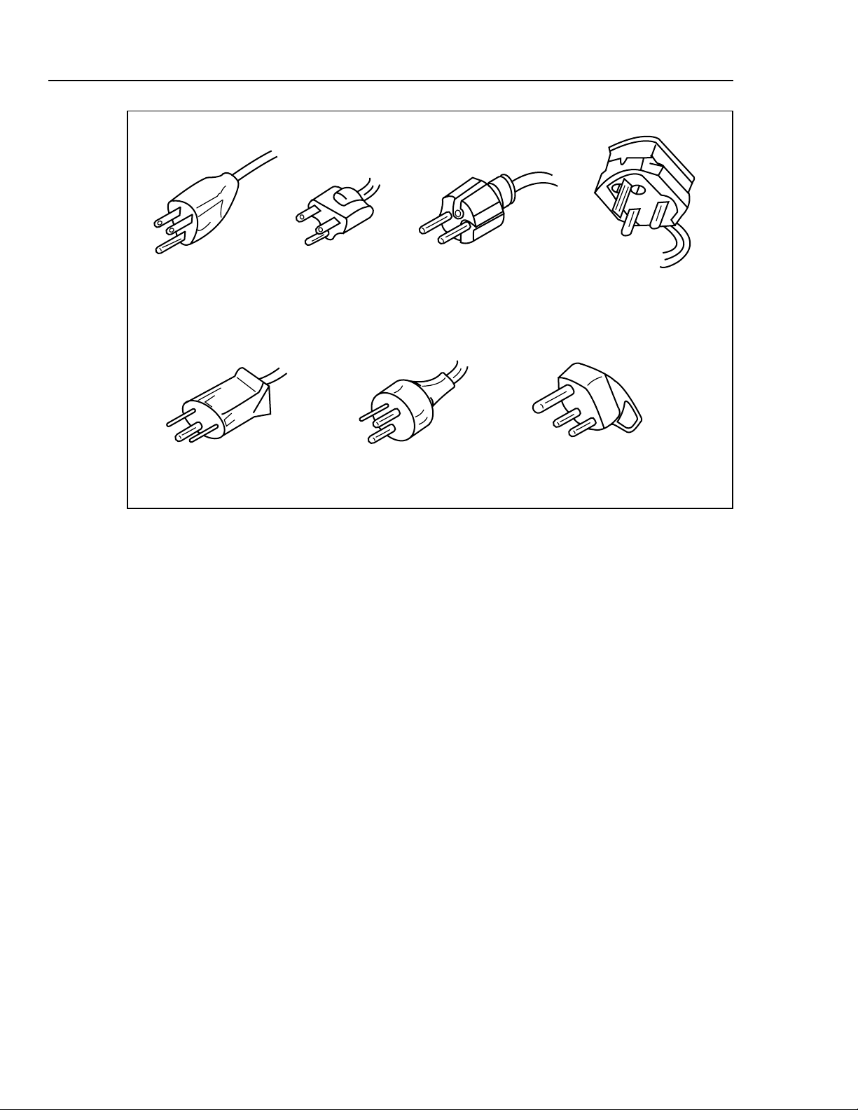
Accompanying the standard should be an ac line power cord appropriate for your
country. Line power cords available from Fluke are listed in Table 2-2 and illustrated in
Figure 2-1. If you have any questions about the contents of the carton you are unpacking,
contact the nearest Fluke Service Center. (A List of Service Centers is located in
Appendix A of this manual.)
For more information about calibration options, refer to Section 1. If a verification test is
required for your acceptance procedures, refer to Section 5 for instructions.
Table 2-1. Standard Equipment
Item Model or Part Number
AC Line Cord (See Table 2-2 and Figure 2-1)
732B/734A Instruction Manual 871723
Table 2-2. AC Line Cords Available for Fluke Instruments
Type Voltage/Current Fluke
North American 120V/15A LC-1
North American 240V/15A LC-2
Universal Euro 220V/16A LC-3
United Kingdom 240V/13A LC-4
Switzerland 220V/10A LC-5
Australian 240V/10A LC-6
South African 240V/5A LC-7
732B/734A
Instruction Manual
2-4
LC-1 LC-2 LC-3 LC-4
LC-5 LC-6 LC-7
k2f.eps
Figure 2-1. Line Power Cords Available for Fluke Instruments
Selecting Line Voltage and Accessing the Fuse 2-3.
Caution
To avoid blowing the ac line fuse, veri fy the position of the line
voltage selection drum before plugging in the line cord. Rotate
the drum if necessary to match local line power.
Caution
To prevent instrument damage, verify that a 1/ 4A, 250V FAST
BLOW fuse is installed. No ot her rating or type of fuse is
acceptable.
The ac input module on the rear panel has four line voltage settings: 100V, 120V, 220V,
and 240V. Each voltage setting has a voltage tolerance of ±10% and accepts line
frequencies of 50 or 60 Hz.
To select line voltage and verify the fuse, or to replace the fuse, refer to Figure 2-2, and
proceed as follows:
1. Disconnect the ac line cord from the wall outlet and the rear panel.
2. Using a small screwdriver, pop open the line voltage selection module door from the
top.
3. Using the screwdriver, pry the tab of the fuse holder to slide out the fuse holder.
4. Verify the fuse type and rating using the data on the rear panel or Figure 2-2, and
replace it.
Loading...