


 Loading...
®
80 Series III
Multimeters
Users Manual
October 1997 Rev.5, 12/03
1997-2003 Fluke Corporation, All rights reserved.
All product names are trademarks of their respective companies.

Lifetime Limited Warranty
Each Fluke 20, 70, 80, 170 and 180 Series DMM will be free from defects in material and workmanship for its lifetime. As used herein, “lifetime” is defined as seven years after Fluke discontinues manufacturing the product, but the warranty period shall be at least ten years from the date of purchase. This warranty does not cover fuses, disposable batteries, damage from neglect, misuse, contamination, alteration, accident or abnormal conditions of operation or handling, including failures caused by use outside of the product’s specifications, or normal wear and tear of mechanical components. This warranty covers the original purchaser only and is not transferable.
For ten years from the date of purchase, this warranty also covers the LCD. Thereafter, for the lifetime of the DMM, Fluke will replace the LCD for a fee based on then current component acquisition costs.
To establish original ownership and prove date of purchase, please complete and return the registration card accompanying the product, or register your product on http://www.fluke.com. Fluke will, at its option, repair at no charge, replace or refund the purchase price of a defective product purchased through a Fluke authorized sales outlet and at the applicable international price. Fluke reserves the right to charge for importation costs of repair/replacement parts if the product purchased in one country is sent for repair elsewhere.
If the product is defective, contact your nearest Fluke authorized service center to obtain return authorization information, then send the product to that service center, with a description of the difficulty, postage and insurance prepaid (FOB Destination). Fluke assumes no risk for damage in transit. Fluke will pay return transportation for product repaired or replaced in-warranty. Before making any non-warranty repair, Fluke will estimate cost and obtain authorization, then invoice you for repair and return transportation.
THIS WARRANTY IS YOUR ONLY REMEDY. NO OTHER WARRANTIES, SUCH AS FITNESS FOR A PARTICULAR PURPOSE, ARE EXPRESSED OR IMPLIED. FLUKE SHALL NOT BE LIABLE FOR ANY SPECIAL, INDIRECT, INCIDENTAL OR CONSEQUENTIAL DAMAGES OR LOSSES, INCLUDING LOSS OF DATA, ARISING FROM ANY CAUSE OR THEORY. AUTHORIZED RESELLERS ARE NOT AUTHORIZED TO EXTEND ANY DIFFERENT WARRANTY ON FLUKE’S BEHALF. Since some states do not allow the exclusion or limitation of an implied warranty or of incidental or consequential damages, this limitation of liability may not apply to you. If any provision of this warranty is held invalid or unenforceable by a court or other decision-maker of competent jurisdiction, such holding will not affect the validity or enforceability of any other provision.
|
Fluke Corporation |
Fluke Europe B.V. |
|
P.O. Box 9090 |
P.O. Box 1186 |
|
Everett WA |
5602 B.D. Eindhoven |
2/02 |
98206-9090 |
The Netherlands |
Table of Contents
Title |
Page |
Introduction.................................................................................................................... |
1 |
Safety Information ......................................................................................................... |
1 |
Your Meter’s Features ................................................................................................... |
4 |
Power-Up Options .................................................................................................... |
11 |
Automatic Power-Off................................................................................................. |
11 |
Input Alert™ Feature ................................................................................................ |
12 |
Making Measurements .................................................................................................. |
12 |
Measuring AC and DC Voltage................................................................................. |
12 |
Testing for Continuity................................................................................................ |
14 |
Measuring Resistance .............................................................................................. |
16 |
Using Conductance for High Resistance or Leakage Tests ..................................... |
18 |
Measuring Capacitance ............................................................................................ |
18 |
Testing Diodes.......................................................................................................... |
21 |
Measuring AC or DC Current.................................................................................... |
22 |
Measuring Frequency............................................................................................... |
25 |
Measuring Duty Cycle............................................................................................... |
27 |
Determining Pulse Width .......................................................................................... |
28 |
i

80 Series III
Users Manual
Analog Bar Graph .......................................................................................................... |
28 |
Model 87 Bar Graph.................................................................................................. |
28 |
Models 83 and 85 Bar Graph .................................................................................... |
29 |
4-1/2 Digit Mode (Model 87) .......................................................................................... |
29 |
MIN MAX Recording Mode ............................................................................................ |
30 |
Touch Hold ®Mode ....................................................................................................... |
32 |
Relative Mode ................................................................................................................ |
32 |
Zoom Mode (Models 83 and 85) ............................................................................... |
32 |
Uses for the Zoom Mode (Models 83 and 85)........................................................... |
33 |
Maintenance .................................................................................................................. |
33 |
General Maintenance................................................................................................ |
33 |
Testing the Fuses...................................................................................................... |
34 |
Replacing the Battery................................................................................................ |
35 |
Replacing the Fuses ................................................................................................. |
35 |
Service and Parts........................................................................................................... |
36 |
Specifications................................................................................................................. |
41 |
ii
|
|
List of Tables |
Table |
Title |
Page |
1. |
International Electrical Symbols ......................................................................................... |
2 |
2. |
Inputs ................................................................................................................................. |
4 |
3. |
Rotary Switch Positions ..................................................................................................... |
5 |
4. |
Pushbuttons ....................................................................................................................... |
6 |
5. |
Display Features ................................................................................................................ |
9 |
6. |
Estimating Capacitance Values Over 5 Microfarads .......................................................... |
20 |
7. |
Functions and Trigger Levels for Frequency Measurements ............................................. |
26 |
8. |
MIN MAX Functions ........................................................................................................... |
31 |
9. |
Replacement Parts............................................................................................................. |
38 |
10. |
Accessories........................................................................................................................ |
40 |
11. |
Models 85 and 87 AC Voltage Function Specifications...................................................... |
42 |
12. |
Model 83 AC Voltage Function Specifications ................................................................... |
43 |
13. |
DC Voltage, Resistance, and Conductance Function Specifications ................................. |
44 |
14. |
Current Function Specifications ......................................................................................... |
45 |
15. |
Capacitance and Diode Function Specifications................................................................ |
47 |
16. |
Frequency Counter Specifications ..................................................................................... |
47 |
17. |
Frequency Counter Sensitivity and Trigger Levels............................................................. |
48 |
18. |
Electrical Characteristics of the Terminals ......................................................................... |
49 |
19. |
MIN MAX Recording Specifications ................................................................................... |
50 |
iii

80 Series III
Users Manual
iv
List of Figures
Figure |
Title |
Page |
1. |
Display Features (Model 87 Shown).......................................................... |
8 |
2. |
Measuring AC and DC Voltage.................................................................. |
13 |
3. |
Testing for Continuity................................................................................. |
15 |
4. |
Measuring Resistance ............................................................................... |
17 |
5. |
Measuring Capacitance............................................................................. |
19 |
6. |
Testing a Diode ......................................................................................... |
21 |
7. |
Measuring Current..................................................................................... |
23 |
8. |
Components of Duty Cycle Measurements ............................................... |
27 |
9. |
Testing the Current Fuses ......................................................................... |
34 |
10. |
Battery and Fuse Replacement ................................................................. |
37 |
11. |
Replaceable Parts ..................................................................................... |
39 |
v

80 Series III
Users Manual
vi

Introduction
Introduction
WWarning
Read "Safety Information" before you use the meter.
Except where noted, the descriptions and instructions in this manual apply to Series III Models 83, 85, 87, and 87/E multimeters. Model 87 is shown in all illustrations.
Safety Information
This meter complies with:
•EN61010.1:1993
•ANSI/ISA S82.01-1994
•CAN/CSA C22.2 No. 1010.1-92
•1000 V Overvoltage Category III, Pollution Degree 2
•UL3111-1
Use the meter only as specified in this manual, otherwise the protection provided by the meter may be impaired.
In this manual, a Warning identifies conditions and actions that pose hazards to the user. A Caution identifies conditions and actions that may damage the meter or the equipment under test.
International symbols used on the meter and in this manual are explained in Table 1.
WWarning
To avoid possible electric shock or personal injury, follow these guidelines:
•Do not use the meter if it is damaged. Before you use the meter, inspect the case. Look for cracks or missing plastic. Pay particular attention to the insulation surrounding the connectors.
•Make sure the battery door is closed and latched before you operate the meter.
•Replace the battery as soon as the battery indicator (M) appears.
1
80 Series III
Users Manual
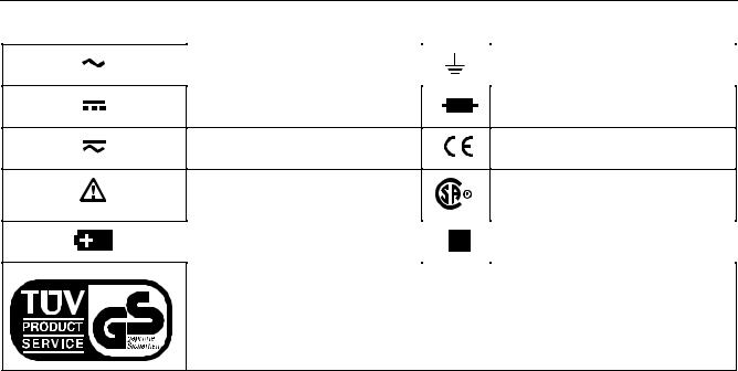
Table 1. International Electrical Symbols
AC (Alternating Current) |
|
Earth ground |
|
|
|
DC (Direct Current)
AC or DC
Refer to the manual for information about this feature.
Fuse
Conforms to European Union directives
Conforms to relevant Canadian Standards Association directives
Battery |
|
Double insulated |
|
|
|
Inspected and licensed by TÜV Product Services.
2
Safety Information
∙Remove test leads from the meter before you open the battery door.
∙Inspect the test leads for damaged insulation or exposed metal. Check the test leads for continuity. Replace damaged test leads before you use the meter.
∙Do not use the meter if it operates abnormally. Protection may be impaired. When in doubt, have the meter serviced.
∙Do not operate the meter around explosive gas, vapor, or dust.
∙Use only a single 9 V battery, properly installed in the meter case, to power the meter.
∙When servicing the meter, use only specified replacement parts.
Caution
To avoid possible damage to the meter or to the equipment under test, follow these guidelines:
∙Disconnect circuit power and discharge all high-voltage capacitors before testing resistance, continuity, diodes, or capacitance.
∙Use the proper terminals, function, and range for your measurements.
∙Before measuring current, check the meter’s fuses. (See "Testing the Fuses".)
3

80 Series III
Users Manual
To protect yourself, use the following guidelines:
∙Use caution when working with voltages above 30 V ac rms, 42 V ac peak, or 60 V dc. Such voltages pose a shock hazard.
∙When using the probes, keep your fingers behind the finger guards.
∙Connect the common test lead before you connect the live test lead. When you disconnect test leads, disconnect the live test lead first.
∙Avoid working alone.
∙When measuring current, turn off circuit power before connecting the meter in the circuit. Remember to place the meter in series with the circuit.
Your Meter’s Features
|
Table 2. Inputs |
|
|
|
|
Terminal |
Description |
Page |
|
|
|
A |
Input for 0 A to 10.00 A |
22 |
|
current measurements |
|
|
|
|
mA μA |
Input for 0 μA to 400 mA |
22 |
|
current measurements |
|
|
|
|
COM |
Return terminal for all |
NA |
|
measurements |
|
|
|
|
V eG |
Input for voltage, |
V: 12 |
|
continuity, resistance, |
e: 16 |
|
diode, capacitance, |
G: 21 |
|
frequency, and duty |
E:18 |
|
cycle measurements |
Frequency: 25 |
|
|
Duty cycle: 27 |
|
|
|
Tables 2 through 5 briefly describe your meter’s features and give page numbers where you can find more detailed information about the features.
4

Your Meter’s Features
Switch Position
K
L
d mV
ReE
G
mA A
μA
Table 3. Rotary Switch Positions
Function
AC voltage measurement
DC voltage measurement
400 mV dc voltage range
R Continuity test
e Resistance measurement
E Capacitance measurement
Diode test
DC or AC current measurements from 0 mA to 10.00 A
DC or AC current measurements from 0 μA to 4000 μA
Page
12
12
12
14
16
18
21
22
22
5

80 Series III
Users Manual
|
|
Table 4. Pushbuttons |
|
|
|
|
|
Button |
Function |
Button Function |
Page |
|
|
|
|
U |
ReE |
Selects capacitance. |
18 |
(Blue |
mA/A, μA |
Switches between dc and ac current. |
22 |
button) |
Power-up |
Disables automatic power-off feature. |
11 |
|
|||
M |
Any switch |
Starts recording of minimum and maximum values. Steps the display through |
30 |
|
position |
MIN, MAX, AVG (average), and present readings. |
|
|
Power-up |
Enables high-accuracy 1-second response time for MIN MAX recording. |
30 |
K |
Any switch |
Switches between the ranges available for the selected function. To return to |
|
|
position |
autoranging, hold the button down for 1 second. |
See ranges in |
|
|
® |
specifications. |
|
|
Manually selecting a range causes the meter to exit the Touch Hold , MIN |
|
|
|
MAX, and REL (relative) modes. |
|
|
Power-up |
For servicing purposes only. |
NA |
|
|||
|
|
|
|
I |
Any switch |
Touch Hold captures the present reading on the display. When a new, stable |
32 |
|
position |
reading is detected, the meter beeps and displays the new reading. |
|
|
MIN MAX |
Stops and starts recording without erasing recorded values. |
30 |
|
recording |
|
|
|
Frequency |
Stops and starts the frequency counter. |
25 |
|
counter |
|
|
|
|
|
|
6

Your Meter’s Features
Button
bModel 87: yellow button
bModels 83, 85: gray button
T
C
(Relative
mode)
F
Function
Any switch position
Continuity
ReE
MIN MAX recording
Power-up
Any switch position
Power-up
Any switch position
Power-up
Table 4. Pushbuttons (cont)
Button Function
Turns the backlight on and off.
For Model 87, hold the yellow button down for one second to enter the 4-1/2 digit mode. To return to the 3-1/2 digit mode, hold the button down only until all display segments turn on (about one second).
Turns the continuity beeper on and off.
On Model 87, switches between 250 μs and 100 ms or 1 s response times.
Disables the beeper for all functions.
Stores the present reading as a reference for subsequent readings. The display is zeroed, and the stored reading is subtracted from all subsequent readings.
For Models 83 and 85, enables zoom mode for the bar graph.
Starts the frequency counter.
Press again to enter duty cycle mode.
Provides >4000 MΩ input impedance for the 400 mV dc range.
Page
NA 29
14
30
NA
32
32
25
27 NA
7

80 Series III
Users Manual
6 |
7 |
8 |
9 |
5 |
|
|
|
4 |
|
|
|
3 |
|
|
1010 |
|
|
|
|
2 |
|
|
10 |
|
|
|
|
|
|
|
11 |
1 |
|
|
|
|
|
12 |
|
|
|
13 |
|
iy1f.eps
Figure 1. Display Features (Model 87 Shown)
8

Your Meter’s Features
Number Feature
A±
BQ
C |
S |
|
|
- |
|
D |
||
|
||
|
|
|
E |
|
|
|
|
FAUTO
G100 ms  MAX MIN AVG
H
IAC DC
Table 5. Display Features
Indication
Polarity indicator for the analog bar graph.
Relative (REL) mode is active.
The continuity beeper is on.
Indicates negative readings. In relative mode, this sign indicates that the present input is less than the stored reference.
The battery is low. WWarning: To avoid false readings, which could lead to possible electric shock or personal injury, replace the battery as soon as the battery indicator appears.
The meter is in autorange mode and automatically selects the range with the best resolution.
Indicators for minimum-maximum recording mode.
Touch Hold is active.
Indicator for ac or dc voltage or current. AC voltage and current is displayed as an rms (root mean square) value.
Page
28
32
14
32
35
NA
30
32
12, 22
9

80 Series III
Users Manual
|
|
Table 5. Display Features (continued) |
|
|
|
|
|
Number |
Feature |
Indication |
Page |
|
|
|
|
J |
A, μA, mA |
A: Amperes (amps). The unit of current. |
22 |
|
|
μA: Microamp. 1 x 10⁻⁶ or 0.000001 amperes. |
|
|
|
mA: Milliamp. 1 x 10⁻³ or 0.001 amperes. |
|
V, mV
μF, nF
V: Volts. The unit of voltage. |
12 |
mV: Millivolt. 1 x 10⁻³ or 0.001 volts. |
|
F: Farad. The unit of capacitance. |
18 |
μF: Microfarad. 1 x 10⁻⁶ or 0.000001 farads. |
|
nF: Nanofarad. 1 x 10⁻⁹ or 0.000000001 farads. |
|
nS
S: Siemen. The unit of conductance. |
18 |
nS: Nanosiemen. 1 x 10⁻⁹ or 0.000000001 siemens. |
|
%
e, Me, ke
Percent. Used for duty cycle measurements. |
27 |
Ω: Ohm. The unit of resistance. |
|
16 |
|
MΩ: Megohm. 1 x 10⁶ or 1,000,000 ohms. |
|
kΩ: Kilohm. 1 x 10³ or 1000 ohms. |
|
Hz, kHz, MHz |
Hz: Hertz. The unit of frequency. |
25 |
|
kHz: Kilohertz. 1 x 10³ or 1000 hertz. |
|
|
MHz: Megahertz. 1 x 10⁶ or 1,000,000 hertz. |
|
10
Loading...