


®
744
Documenting Process Calibrator
Users Manual
PN 691287
September 1998 Rev.1, 2/99
© 1998,1999 Fluke Corporation. All rights reserved. Printed in U.S.A. All product names are trademarks of their respective companies.
LIMITED WARRANTY & LIMITATION OF LIABILITY
Each Fluke product is warranted to be free from defects in material and workmanship under normal use and service. The warranty period is three years and begins on the date of shipment. Parts, product repairs and services are warranted for 90 days. This warranty extends only to the original buyer or end-user customer of a Fluke authorized reseller, and does not apply to fuses, disposable batteries or to any product which, in Fluke’s opinion, has been misused, altered, neglected or damaged by accident or abnormal conditions of operation or handling. Fluke warrants that software will operate substantially in accordance with its functional specifications for 90 days and that it has been properly recorded on non-defective media. Fluke does not warrant that software will be error free or operate without interruption.
Fluke authorized resellers shall extend this warranty on new and unused products to end-user customers only but have no authority to extend a greater or different warranty on behalf of Fluke. Warranty support is available if product is purchased through a Fluke authorized sales outlet or Buyer has paid the applicable international price. Fluke reserves the right to invoice Buyer for importation costs of repair/replacement parts when product purchased in one country is submitted for repair in another country.
Fluke’s warranty obligation is limited, at Fluke’s option, to refund of the purchase price, free of charge repair, or replacement of a defective product which is returned to a Fluke authorized service center within the warranty period.
To obtain warranty service, contact your nearest Fluke authorized service center or send the product, with a description of the difficulty, postage and insurance prepaid (FOB Destination), to the nearest Fluke authorized service center. Fluke assumes no risk for damage in transit. Following warranty repair, the product will be returned to Buyer, transportation prepaid (FOB Destination). If Fluke determines that the failure was caused by misuse, alteration, accident or abnormal condition of operation or handling, Fluke will provide an estimate of repair costs and obtain authorization before commencing the work. Following repair, the product will be returned to the Buyer transportation prepaid and the Buyer will be billed for the repair and return transportation charges (FOB Shipping Point).
THIS WARRANTY IS BUYER’S SOLE AND EXCLUSIVE REMEDY AND IS IN LIEU OF ALL OTHER WARRANTIES, EXPRESS OR IMPLIED, INCLUDING BUT NOT LIMITED TO ANY IMPLIED WARRANTY OF MERCHANTABILITY OR FITNESS FOR A PARTICULAR PURPOSE. FLUKE SHALL NOT BE LIABLE FOR ANY SPECIAL, INDIRECT, INCIDENTAL OR CONSEQUENTIAL DAMAGES OR LOSSES, INCLUDING LOSS OF DATA, WHETHER ARISING FROM BREACH OF WARRANTY OR BASED ON CONTRACT, TORT, RELIANCE OR ANY OTHER THEORY.
Since some countries or states do not allow limitation of the term of an implied warranty, or exclusion or limitation of incidental or consequential damages, the limitations and exclusions of this warranty may not apply to every buyer. If any provision of this Warranty is held invalid or unenforceable by a court of competent jurisdiction, such holding will not affect the validity or enforceability of any other provision.
Fluke Corporation |
Fluke Europe B.V. |
P.O. Box 9090 |
P.O. Box 1186 |
Everett WA 98206-9090 |
5602 B.D. |
U.S.A |
Eindhoven, The Netherlands |
5/94
Table of Contents
Title |
Page |
Introduction.................................................................................................................... |
1 |
Standard Equipment...................................................................................................... |
3 |
Safety Information ......................................................................................................... |
7 |
Getting Started Exercise ............................................................................................... |
10 |
Operating Features ....................................................................................................... |
12 |
Input and Output Jacks............................................................................................. |
12 |
Keys ........................................................................................................................ |
14 |
Display...................................................................................................................... |
17 |
Setting Up the Calibrator ............................................................................................... |
19 |
Using the Strap and Bail........................................................................................... |
19 |
Charging the Battery................................................................................................. |
20 |
Battery Life ............................................................................................................... |
22 |
Preserving Battery Life ............................................................................................. |
23 |
Using the Optional Battery Eliminator....................................................................... |
23 |
Selecting the Display Language ............................................................................... |
24 |
Adjusting the Display Contrast.................................................................................. |
24 |
i

744
Users Manual
Displaying the Date and Time ................................................................................... |
24 |
Using the Backlight ................................................................................................... |
26 |
Personalizing the Calibrator ...................................................................................... |
26 |
Using Measure Mode..................................................................................................... |
28 |
Measurement Ranges............................................................................................... |
28 |
Measuring Electrical Parameters .............................................................................. |
28 |
Testing Continuity ..................................................................................................... |
30 |
Measuring Pressure .................................................................................................. |
30 |
Measuring Temperature............................................................................................ |
34 |
Using Thermocouples .......................................................................................... |
34 |
Using Resistance-Temperature Detectors (RTDs) ............................................... |
37 |
Measurement Scale .................................................................................................. |
41 |
Linear-Output Transmitters .................................................................................. |
41 |
Square-Law Process Variables ............................................................................ |
42 |
Measuring or Sourcing with Custom Units ................................................................ |
43 |
Using the 700-IV Current Shunt ................................................................................ |
44 |
Damping Your Measurements................................................................................... |
44 |
Using Source Mode ....................................................................................................... |
46 |
Sourcing Electrical Parameters................................................................................. |
46 |
Simulating a 4 to 20 mA Transmitter......................................................................... |
48 |
Supplying Loop Power .............................................................................................. |
50 |
Sourcing Pressure..................................................................................................... |
52 |
Simulating Thermocouples........................................................................................ |
55 |
Simulating RTDs ....................................................................................................... |
56 |
Source Scale............................................................................................................. |
59 |
Linear-Responding Transmitters .......................................................................... |
59 |
Square-Law Process Variables ............................................................................ |
59 |
Stepping and Ramping the Output Value.................................................................. |
60 |
ii

|
Contents (continued) |
Using Manual Step .............................................................................................. |
60 |
Using Auto Step................................................................................................... |
61 |
Ramping the Output............................................................................................. |
62 |
Simultaneous Measure/Source ..................................................................................... |
65 |
Calibrating a Process Instrument .................................................................................. |
68 |
Generating “As Found” Test Data............................................................................. |
68 |
Adjusting the Transmitter.......................................................................................... |
73 |
“As Left” Test Run .................................................................................................... |
74 |
Test Comments ........................................................................................................ |
75 |
Calibrating a Delta-Pressure Flow Instrument .......................................................... |
75 |
Calibrating a Limit Switch ......................................................................................... |
76 |
Transmitter Mode .......................................................................................................... |
79 |
Memory Operations....................................................................................................... |
81 |
Saving Results.......................................................................................................... |
81 |
Reviewing Memory ................................................................................................... |
83 |
Data Logging ............................................................................................................ |
83 |
Recording Min and Max Measurements ................................................................... |
86 |
Running a Preloaded Task ....................................................................................... |
86 |
Clearing Memory ...................................................................................................... |
86 |
Using the Built-in Calculator .......................................................................................... |
87 |
Saving to and Recalling from the Registers.............................................................. |
87 |
Using the Calculator to Set the Source Value .......................................................... |
88 |
Quick Guide to Applications .......................................................................................... |
88 |
Communicating with a PC ............................................................................................. |
98 |
Maintenance.................................................................................................................. |
98 |
Replacing the Battery Pack ...................................................................................... |
98 |
Internal Lithium Backup Battery................................................................................ |
99 |
Cleaning the Calibrator............................................................................................. |
99 |
iii

744
Users Manual
Calibration Data ........................................................................................................ |
99 |
In Case of Difficulty ................................................................................................... |
99 |
Service Center Calibration or Repair ........................................................................ |
100 |
Replacement Parts ........................................................................................................ |
101 |
Accessories.................................................................................................................... |
102 |
Specifications................................................................................................................. |
104 |
DC Voltage Measurement......................................................................................... |
105 |
AC Voltage Measurement ......................................................................................... |
106 |
DC Current Measurement ......................................................................................... |
107 |
Resistance Measurement.......................................................................................... |
107 |
Continuity Testing ..................................................................................................... |
108 |
Frequency Measurement .......................................................................................... |
108 |
DC Voltage Output .................................................................................................... |
109 |
DC Current Output .................................................................................................... |
110 |
Resistance Sourcing ................................................................................................. |
111 |
Frequency Sourcing .................................................................................................. |
112 |
Temperature, Thermocouples................................................................................... |
113 |
Temperature, Resistance Temperature Detectors .................................................... |
116 |
Loop Power Supply ................................................................................................... |
118 |
Top and Bottom Limits of Ranges with Auto Range On............................................ |
119 |
General Specifications .............................................................................................. |
121 |
Index ............................................................................................................................. |
125 |
iv
List of Tables
Table |
Title |
Page |
1. |
Summary of Source and Measure Functions ..................................................................... |
4 |
2. |
Input/Output Jacks and Connectors ................................................................................... |
12 |
3. |
Key Functions .................................................................................................................... |
15 |
4. |
Battery Life ......................................................................................................................... |
22 |
5. |
Thermocouple Types Accepted.......................................................................................... |
35 |
6. |
RTD Types Accepted ......................................................................................................... |
37 |
7. |
Simultaneous MEASURE/SOURCE Functions with Loop Power Disabled ....................... |
66 |
8. |
Simultaneous MEASURE/SOURCE Functions with Loop Power Enabled ........................ |
67 |
9. |
Replacement Parts............................................................................................................. |
101 |
v

744
Users Manual
vi
List of Figures
Figure |
Title |
Page |
1. |
Standard Equipment .......................................................................................................... |
5 |
2. |
Definition of Symbols ......................................................................................................... |
7 |
3. |
Jumper Connections for Demonstration............................................................................. |
11 |
4. |
Measure/Source Example .................................................................................................. |
11 |
5. |
Input/Output Jacks and Connectors ................................................................................... |
13 |
6. |
Keys ................................................................................................................................... |
14 |
7. |
Elements of a Typical Display ............................................................................................ |
18 |
8. |
Using the Bail and Installing the Strap ............................................................................... |
19 |
9. |
Removing the Battery and Using the Charger.................................................................... |
21 |
10. |
Electrical Measurement Connections................................................................................. |
29 |
11. |
Gage and Differential Pressure Modules ........................................................................... |
31 |
12. |
Connections for Measuring Pressure ................................................................................. |
33 |
13. |
Measuring Temperature with a Thermocouple................................................................... |
36 |
14. |
Using a Jumper Correctly................................................................................................... |
39 |
15. |
Measuring Temperature with an RTD ................................................................................ |
40 |
16. |
Electrical Sourcing Connections ........................................................................................ |
47 |
17. |
Connections for Simulating a 4 to 20 mA Transmitter........................................................ |
49 |
vii

744
Users Manual
18. |
Connections for Supplying Loop Power.............................................................................. |
51 |
19. |
Connections for Sourcing Pressure .................................................................................... |
54 |
20. |
Connections for Simulating a Thermocouple...................................................................... |
57 |
21. |
Connections for Simulating an RTD ................................................................................... |
58 |
22. |
Checking a Relay Output Trip Alarm .................................................................................. |
64 |
23. |
Calibrating a Thermocouple Temperature Transmitter....................................................... |
70 |
24. |
Limit Switch Terminology.................................................................................................... |
76 |
25. |
Calibrating a Chart Recorder.............................................................................................. |
89 |
26. |
Measuring Voltage Drop ..................................................................................................... |
89 |
27. |
Monitoring AC Line Voltage and Frequency ....................................................................... |
90 |
28. |
Calibrating a Current-to-Pressure (I/P) Transmitter ............................................................ |
91 |
29. |
Measuring the Output Current of a Transmitter .................................................................. |
92 |
30. |
Measuring a Precision Resistor .......................................................................................... |
93 |
31. |
Sourcing Resistance........................................................................................................... |
93 |
32. |
Checking a Switch .............................................................................................................. |
94 |
33. |
Checking a Tachometer...................................................................................................... |
94 |
34. |
Calibrating a Pressure-to-Current (P/I) Transmitter............................................................ |
95 |
35. |
Calibrating a mV to Current Transmitter ............................................................................. |
96 |
36. |
Checking a Vortex Sheeding Flowmeter ............................................................................ |
97 |
37. |
LCD Operating Environment Specification ......................................................................... |
123 |
viii
Documenting Process Calibrator
Introduction
The Fluke 744 Documenting Process Calibrator (hereafter referred to as the calibrator) is a batterypowered, hand-held instrument that measures and sources electrical and physical parameters, and provides basic HARTâ communicator functions when used with HART-capable transmitters. Refer to the 744 HARTâ Mode Users Guide for instructions on how to use the HART communication feature.
The calibrator lets you troubleshoot, calibrate, verify, and document your work on process instruments. Calibrator Specifications are at the back of the manual.
A summary of the measuring and sourcing functions provided by the calibrator is shown in Table 1. In
addition to these functions, the calibrator has the following features:
∙General features:
An analog display to make it easy to read measurements when the input is unstable.
A setup option that lets you set the display to English, French, German, Italian, or Spanish.
A thermocouple (TC) input/output jack and internal isothermal block with automatic reference-junction temperature compensation. Or, you can manually enter an external temperature reference.
The ability to store results for later review.
1

744
Users Manual
The ability to automatically log up to 8,000 data points.
A serial computer interface for uploading/downloading tasks, lists, and results.
Automatic calibration procedures for transmitters and limit switches using split screen MEASURE/SOURCE mode.
Transmitter mode in which the calibrator can be configured to emulate the functions of a process instrument.
Built-in calculator with square-root function, and accessible registers containing measure and source values.
An optional bar code wand for entering alphanumeric characters.
∙Measuring features:
Damping (smoothing of the last several readings), with display indicator of damped status.
Display of measurements in engineering units, percent of scale, square-law inputs, or custom units.
The ability to capture and display minimum and maximum measured levels.
∙Sourcing features:
The ability to set source values to engineering units, percent of scale, square-law outputs, or custom units.
Manual and automatic stepping, and an output ramp feature for testing limit switches. Trip detect is either a 1 V change or a continuity status change (Open or Short) from one ramp increment to the next.
For performance testing and calibration instructions order the 74X Series Calibration Manual
(PN 602505).
To contact Fluke, call:
USA and Canada:
1-888-99-FLUKE (1-888-993-5853)
Europe: +31 402-678-200
Japan: +81-3-3434-0181
Singapore: +65-738-5655
Anywhere in the world: +1-425-356-5500
Or visit us on the World Wide Web: www.fluke.com
2

Documenting Process Calibrator
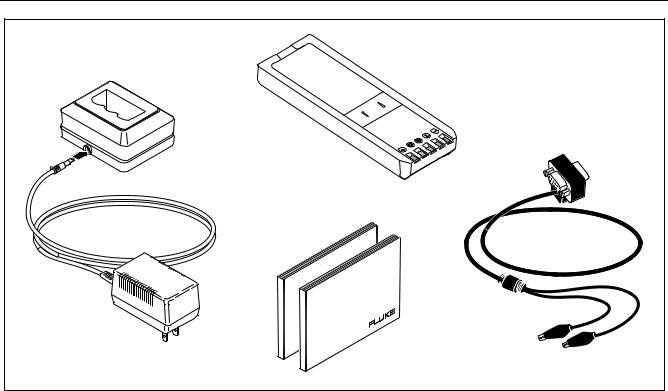
Standard Equipment
Standard Equipment
The items listed below and shown in Figure 1 are included with your calibrator. If the calibrator is damaged or something is missing, contact the place of purchase immediately. To order replacement parts or spares, see the user-replaceable parts list at the end of this manual.
∙TL24 industrial test leads (two sets)
∙AC20 test clips (two sets)
∙TP20 test probes (one set)
∙HART interface cable
∙BP7235 rechargeable nickel-metal hydride pack
∙BC7217 battery charger with Instruction Sheet
∙Adjustable quick-release strap (PN 946769)
∙Jumper for three-wire RTD measurement connections (two included, PN 944632)
∙744 Users Manual
English (PN 691287) French (PN 691300) German (PN 691311) Italian (PN 691318) Spanish (PN 691303)
∙744 HARTâ Mode Users Guide
English (PN 691292) French (PN 691326) German (PN 691334) Italian (PN 691337) Spanish (PN 691329)
∙DPC/TRACKä Software utility version with interface cable (9-pin male-female straightthrough, PN 943738).
3

|
Table 1. Summary of Source and Measure Functions |
|
|
|
|
Function |
Measure |
Source |
vdc V |
0 V to +/-300 V |
0 V to 15 V (10 mA max) |
hac V |
0 V to 300 V rms, 20 Hz to 5 kHz |
No sourcing |
hFrequency |
1 Hz to 1 kHz (100 mV to 300 V rms) |
0.1 V to 10 V p-p sine wave, or peak square |
|
1 kHz to 30 kHz (0.5 V to 30 V rms) |
wave, 0 Hz to 50 kHz |
|
30 kHz to 50 kHz (1 V to 30 V rms) |
|
qResistance |
0 Ω to 11 k Ω |
0 Ω to 11 k Ω |
mdc Current |
0 mA to 110 mA |
0 to 22 mA (28 V max), sourcing or sinking |
qContinuity |
Beep and the word Short indicates continuity |
No sourcing |
tThermocouple |
Types E, N, J, K, T, B, R, S, C, L, or U |
|
tRTD |
100 Ω Platinum (3926) |
|
|
100 Ω Platinum (385) |
|
|
120 Ω Nickel (672) |
|
|
200 Ω Platinum (385) |
|
|
500 Ω Platinum (385) |
|
|
1000 Ω Platinum (385) |
|
|
10 Ω Copper (427) |
|
|
100 Ω Platinum (3916) |
|
pPressure |
27 modules ranging from 0 to 10 in. H2O |
Note |
|
(2.5 kPa) to 0 to 10,000 psi (69,000 kPa) |
|
sLoop Power |
24 or 28 V (22 mA max) |
|
Note: Use an external hand pump or other pressure source as a pressure stimulus for the source pressure function.
4

Documenting Process Calibrator
Standard Equipment
|
|
V |
|
V |
|
TC |
|
|
|
Hz |
|
RTD |
|
|
|
|
|
|
||
|
|
7 |
|
8 |
9 |
CLEAR |
|
|
|
|
|
|
( ZERO) |
|
|
4 |
|
5 |
6 |
|
|
|
1 |
2 |
3 |
|
|
AC20 |
|
0 |
|
. |
|
ENTER |
|
|
|
|
|||
|
|
|
|
|
|
|
Test Clip |
V |
mA |
|
mA |
|
V |
RTD |
|
|
RTD |
|
|
|
|
|
|
|
|
||
(2 Red and 2 Black) |
|
SOURCE |
|
MEAS |
300V |
TC |
|
|
|
MAX |
|||
|
|
30V MAX |
|
|
|
|
TL24 |
|
|
|
|
|
|
Test Leads |
|
|
|
|
|
|
(2 Red and 2 Black) |
|
|
|
|
|
|
Jumper |
|
|
|
|
|
|
(2 Black) |
|
|
|
|
|
|
TP20 |
|
|
|
|
|
|
Test Probe |
|
|
|
|
|
|
(1 Red and 1 Black) |
|
|
|
|
|
|
|
Strap |
|
|
|
|
|
|
|
|
|
|
|
ot01f.eps |
Figure 1. Standard Equipment
5
744
Users Manual
BC7217 |
BP7235 |
Nickel-Metal Hydride |
|
Battery Charger |
Battery Pack |
HART
Interface
Cable
HART Mode
Users Guide
Users
Manual
ot02f.eps
Figure 1. Standard Equipment (cont)
6

Documenting Process Calibrator
Safety Information
Safety Information
This calibrator is designed and tested in accordance with IEC1010-1 and CAN/CSA C22.2 No. 1010.1-92. Use the calibrator only as specified in
this manual, otherwise the protection provided by the calibrator may be impaired.
Symbols used on the calibrator and in this manual are explained in Figure 2.
|
|
|
|
|
|
|
|
|
|
|
AC-Alternating Current |
|
CAUTION see explanation in manual |
|
|
|
|
|
|
|
|
|
|
|
|
|
|
|
|
|
|
|
|
|
|
|
|
|
|
|
DC-Direct Current |
|
Common (LO) Input equipotentiality |
|
|
|
|
|
|
|
|
|
|
|
|
|
|||
|
|
|
|
|
|
|
|
|
|
|
|
|
|
|
|
|
|
|
|
|
|
|
|
|
|
Fuse |
|
Equipment protected throughout by DOUBLE INSULATION or |
|
|
|
|
|
|
|
|
|
|
|
|
|
|
REINFORCED INSULATION |
|
|
|
|
|
|
|
|
|
|
|
|
|
|
|
|
|
|
|
|
|
|
|
|
|
|
|
Pressure |
|
Conforms to relevent European Union directives. |
|
|
|
|
|
|
|
|
|
|
|
|
|
|
|
|
|
|
|
|
|
|
|
|
|
|
|
ON/OFF |
|
Conforms to relevent Canadian Standards Association directives. |
|
|
|
|
|
|
|
|
|
|
|
|
|
|
|
|
|
|
|
|
|
|
|
|
|
|
|
|
|
Overvoltage (Installation) Category II, Pollution Degree 2 per |
|
|
|
|
|
|
|
|
|
|
|
|
Recycling |
CAT II |
IEC 1010-1 refers to the level of Impluse Withstand Voltage protection |
|
|
|
|
|
|
|
|
|
|
|
|
|
|
provided. Typical locations include; Mains Wall outlets, local appliances |
|
|
|
|
|
|
|
|
|
|
|
|
|
|
and PORTABLE EQUIPMENT. |
|
|
|
|
|
|
|
|
|
|
|
|
|
|
|
|
|
|
|
|
|
|
|
|
|
|
|
|
|
gj56f.eps |
|
Figure 2. Definition of Symbols
7

744
Users Manual
Safety Information (cont)
A Warning identifies conditions and actions that pose hazards to the user; a Caution identifies conditions and actions that may damage the calibrator or the equipment under test.
 Warning
To avoid electric shock or personal injury, adhere to the following practices:
∙Do not use the calibrator if it is damaged. Before you use the calibrator, inspect the insulating cover. Look for cracks or missing plastic. Pay particular attention to the insulation surrounding the connectors.
∙Disconnect the power and discharge all highvoltage capacitors in the equipment under test before testing resistance or continuity.
∙Inspect the test leads for damaged insulation or exposed metal. Check test lead continuity. Replace damaged test leads before using the calibrator.
∙Do not use the calibrator if it operates abnormally. Protection may be impaired. When in doubt, have the calibrator serviced.
∙Select the proper function and range for your measurement.
∙Use caution when working above 30 V ac rms, 42 V ac pk, or 60 V dc. Such voltages pose a shock hazard.
∙When using the probes, keep your fingers away from the probe contacts. Keep your fingers behind the finger guards on the probes.
∙Connect the common test lead before you connect the live test lead. When you disconnect test leads, disconnect the live test lead first.
∙Replace the battery as soon as there is a low battery indication on the display. The possibility of false readings can lead to electric shock and personal injury.
8

Documenting Process Calibrator
Safety Information
Safety Information (cont)
 Warning (cont)
∙Do not apply more than the rated voltage, as marked on the calibrator, between the terminals, or between any terminal and earth ground.
∙When using probes, keep your fingers behind the finger guards.
∙Do not use the calibrator with any part of the case or cover removed.
∙Do not operate the calibrator around explosive gas, vapor, or dust.
∙When using a pressure module, make sure the process pressure line is shut off and depressurized before you connect it to or disconnect it from the pressure module.
∙Disconnect test leads before changing to another measure or source function.
∙When servicing the calibrator, use only specified replacement parts.
∙Do not use any battery eliminator other than the Fluke model BE9005 Battery Eliminator.
Caution
To avoid possible damage to the calibrator or the equipment under test, follow these guidelines:
∙Disconnect circuit power and discharge all high-voltage capacitors before testing resistance, continuity, diodes, or capacitance.
∙Use the proper terminals, function, and range for your measurements.
9

744
Users Manual
Getting Started Exercise
The following is a brief getting started exercise that will make it easier to understand the instructions in the rest of the manual.
1.When you first unpack the calibrator, you will need to charge the battery. See Figure 9 and charge the battery for 2 hours.
2.Reinstall the battery in the calibrator.
3.Connect the calibrator’s voltage output to its
voltage input as follows: connect leftmost pair of jacks (V Ω RTD SOURCE) to the right most pair of jacks (V MEAS). (See Figure 3.)
4.Press oto turn on the calibrator. Press uand dto adjust the display contrast for the best looking display. The calibrator powers up in the dc voltage measurement function, and is taking readings on the V MEAS pair of input jacks.
5.Press sto switch to the SOURCE screen. The calibrator is still measuring dc voltage, and you can see the active measurements at the top of the display.
6.Press vto select dc voltage sourcing. Press 5 on the keypad and eto begin sourcing 5.0000 V dc.
7.Now press Mto go to the split-screen, simultaneous MEASURE/SOURCE mode. The calibrator is simultaneously sourcing dc volts and measuring dc volts. You can see the measurement readings in the top window, and the active source value in the bottom window as shown in Figure 4.
10
Documenting Process Calibrator
Getting Started Exercise
V
RTD
30V MAX
V |
|
7 |
|
4 |
|
1 |
2 |
|
0 |
mA |
|
SOURCE |
|
30V |
|
MAX |
|
V |
|
Hz |
|
8 |
9 |
5 |
6 |
3 |
|
. |
|
mA |
V |
RTD |
|
CAT |
|
MEAS |
300V |
30V |
MAX |
MAX |
|
TC
RTD
CLEAR ( ZERO)
ENTER
TC
gj4s.eps
Figure 4. Measure/Source Example
ot03f.eps
Figure 3. Jumper Connections for Demonstration
11

744
Users Manual
Operating Features
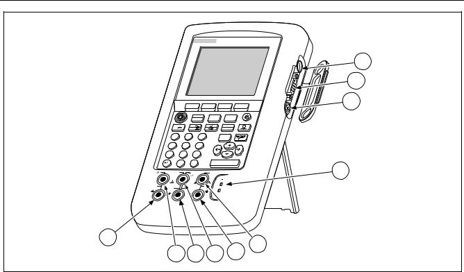
Input and Output Jacks
Figure 5 shows the calibrator input and output jacks. Table 2 explains their use.
|
|
Table 2. Input/Output Jacks and Connectors |
|
|
|
No. |
Name |
Description |
|
|
|
1 |
Battery Eliminator jack |
Jack for the Model BE9005 Battery Eliminator. Use the battery eliminator for bench-top |
|
|
applications where ac line power is available. This input does not charge the battery. |
2 |
w SERIAL PORT |
Connects the calibrator to an RS-232 serial port on a personal computer. |
|
|
|
3 |
Pressure module |
Connects the calibrator to a pressure module. |
|
connector |
|
4 |
TC input/output |
Jack for measuring or simulating thermocouples. This jack accepts a miniature |
|
|
polarized thermocouple plug with flat, in-line blades spaced 7.9 mm (0.312 in) center to |
|
|
center. |
5, 6 |
wMEAS V jacks |
Input jacks for measuring voltage, frequency, or threeor four-wire RTDs (Resistance |
|
|
Temperature Detectors). |
7, 8 |
wSOURCE mA, |
Jacks for sourcing or measuring current, measuring resistance and RTDs, and |
|
MEAS mA Ω RTD |
supplying loop power. |
|
jacks |
|
9,10 |
wSOURCE V Ω RTD |
Output jacks for sourcing voltage, resistance, frequency, and for simulating RTDs. |
|
jacks |
|
12
Documenting Process Calibrator
Operating Features


 744 DOCUMENTING PROCESS CALIBRATOR
|
|
|
MEAS |
mA |
SETUP |
|
|
|
|
SOURCE |
|||
|
|
|
|
|
||
|
V |
|
V |
|
|
TC |
|
|
Hz |
|
|
RTD |
|
|
|
|
|
|
||
|
7 |
|
8 |
9 |
|
CLEAR |
|
|
|
|
|
|
( ZERO) |
|
4 |
|
5 |
6 |
|
|
|
1 |
2 |
3 |
|
|
|
|
0 |
|
. |
|
|
ENTER |
|
|
|
|
|
||
V |
mA |
|
mA |
|
V |
|
RTD |
|
|
RTD |
|
|
|
|
|
|
|
|
|
|
|
|
|
CAT |
|
|
|
30V |
SOURCE |
|
MEAS |
|
300V |
TC |
MAX |
30V |
|
30V |
|
MAX |
|
|
MAX |
|
MAX |
|
|
|
10
5
9 |
8 |
7 |
6 |
1
2
3
4
ot05f.eps
Figure 5. Input/Output Jacks and Connectors
13
744
Users Manual
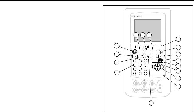
Keys
Figure 6 shows the calibrator keys and Table 3 explains their functions. The softkeys are the four unmarked blue keys just below the display. Softkey functions are defined by the labels that appear above the softkey during operation. Softkey labels and other display text are shown in this manual in bold type, for example, Choices.
744 DOCUMENTING PROCESS CALIBRATOR
1 2 3
4
16 |
|
|
|
|
5 |
|
|
|
|
|
|
|
MEAS |
mA |
SETUP |
|
|
|
SOURCE |
|
|
||
15 |
|
|
|
6 |
|
V |
|
TC |
|
||
V |
|
|
|
||
Hz |
|
RTD |
|
|
|
|
|
|
|
||
7 |
8 |
9 |
CLEAR |
|
7 |
( ZERO) |
|
||||
14 |
|
|
|
|
|
4 |
5 |
6 |
|
|
8 |
|
|
|
|
|
|
1 |
2 |
3 |
|
|
9 |
13 |
|
. |
|
|
|
0 |
ENTER |
|
|
||
V |
mA |
mA |
V |
|
10 |
RTD |
|
RTD |
|
|
|
|
|
|
|
|
|
|
|
CAT |
|
|
11 |
30V |
SOURCE |
MEAS |
300V |
TC |
|
MAX |
30V |
30V |
|
||
|
MAX |
MAX |
|
|
|
12
ot06f.eps
Figure 6. Keys
14

|
|
|
|
Documenting Process Calibrator |
|
|
|
|
Operating Features |
|
|
|
|
|
|
|
|
|
Table 3. Key Functions |
|
|
|
|
|
|
|
No. |
Name |
Description |
|
|
|
|
|
|
|
1 |
Mkey |
Cycles the calibrator through MEASURE, SOURCE, and MEASURE/SOURCE modes. |
|
2 |
mkey |
Selects mA (current) measure or source function. For loop power on/off, go to the Setup |
|
|
|
|
|
mode. |
|
|
|
|
|
|
3 |
skey |
Enters and exits Setup mode to modify operating parameters. |
|
|
4 |
Softkeys |
Perform the function defined by the label above each key on the display. |
|
|
|
|
|
|
|
|
5 |
Ckey |
Turns the backlight on and off. |
|
|
6 |
pkey |
Selects the pressure measurement or sourcing function. |
|
7 |
tkey |
Selects TC (thermocouple) or RTD (resistance temperature detector) measurement or |
|
|
|
|
|
sourcing functions. |
|
|
|
|
|
|
8 |
rkey |
Toggles between HART communication mode and analog operation. In calculator mode, this |
|
|
|
|
|
key provides the square root function. |
|
|
|
|
|
|
9 |
ckey |
Clears a partial data entry, or zeros the output when in the SOURCE mode. When using a |
|
|
|
|
|
pressure module, zeros the pressure module reading. |
|
|
|
|
|
15

744
Users Manual
|
|
Table 3. Key Functions (cont) |
|
|
|
No. |
Name |
Description |
|
|
|
10 |
u, d, L, and R |
∙ Adjust the display contrast. |
|
keys |
∙ Make choices from lists on the display. |
|
|
∙ Increase or decrease the source level when using the step feature. |
|
|
∙ In calculator mode, provide arithmetic functions (+ - ÷ ×). |
|
|
|
11 |
ekey |
Terminates a numeric entry when setting a source value, or confirms your choice in a |
|
|
list. In calculator mode, provides the equals arithmetic operator (=). |
|
|
|
12 |
qkey |
Toggles between resistance and continuity functions in MEASURE mode, or selects |
|
|
the resistance function in SOURCE mode. |
|
|
|
13 |
Numeric keypad |
Used whenever a numeric entry is required. |
|
|
|
14 |
hkey |
Toggles between ac voltage and frequency functions in MEASURE mode, or selects |
|
|
frequency output in SOURCE mode. |
|
|
|
15 |
vkey |
Selects the dc voltage function in MEASURE mode, or selects dc voltage in SOURCE |
|
|
mode. |
|
|
|
16 |
okey |
Turns the power on and off. |
16

Documenting Process Calibrator
Operating Features
Display
Figure 7 shows the features of a typical display. The display shown is MEASURE mode. Near the top of the display is “Source Off.” This is the area of the display that shows what is happening in the other mode (SOURCE or MEASURE). The other parts of the display are as follows:
∙Status Bar: shows the time and date (if set in Setup mode), and shows the status of Loop Power, Battery Save, and Backlight Timeout; all of which are set in Setup mode. The low battery and backlight on symbols also appear here.
∙Mode Indicator: Shows whether the calibrator is in MEASURE or SOURCE mode. In split screen MEASURE/SOURCE mode, there is a Mode Indicator for each window.
∙Measured Value: Shows the measured value in your choice of engineering units or percent of scale.
∙Range Status: Shows whether Auto Range is on, and what range is currently being used.
∙Custom Units Indicator: Shows that the displayed units are custom. The original engineering units of the measure or source function are not displayed.
∙Secondary Value: Shows the measure or source value in original engineering units whenever scaling or custom units are active.
17
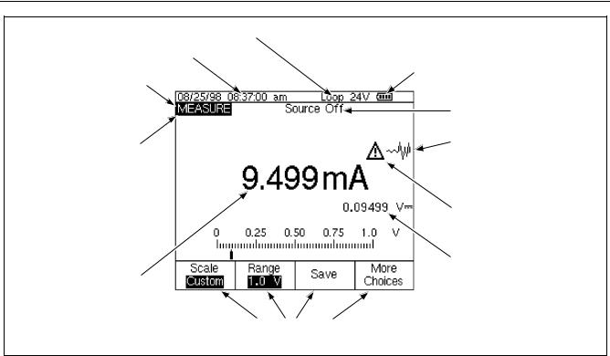
744
Users Manual
Loop Power Annunciator
Time and Date Display
Status Bar
Mode Indicator
Measured Value
Softkey Labels
Battery Gauge
Source Status
Undamped (Unsettled)
Indicator
Custom Units Indicator
Secondary Value
ot07c.eps
Figure 7. Elements of a Typical Display
18
Documenting Process Calibrator
Setting Up the Calibrator
Setting Up the Calibrator
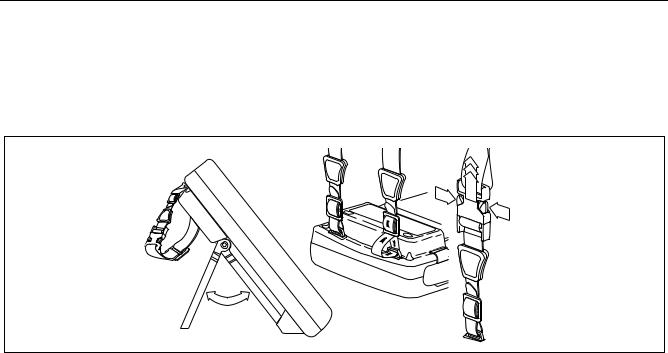
Using the Strap and Bail
After you unpack the calibrator, attach its carrying strap as shown in Figure 8. You can adjust the strap as necessary to hang the calibrator on any sturdy
support. Figure 8 also shows you how to open the bail to stand the calibrator at a comfortable viewing angle for benchtop use.
gj8f.eps
Figure 8. Using the Bail and Installing the Strap
19

744
Users Manual
Charging the Battery
wBefore you use the calibrator for the first time, charge its battery pack in the external battery charger. The Model BC7217 charger charges both the NiMH and Ni-Cd battery packs.
the charger). Full charge is maintained after that time in trickle-charge mode (blinking indicator light on the charger). Switching between charging modes is automatic. You can leave the battery pack on trickle charge indefinitely without damage.
Figure 9 shows how to remove the battery. Remove the battery door and tap the calibrator with your hand to get the battery out. Place the battery in the charger and connect the charger to line power. The charger automatically senses line voltage and adjusts itself accordingly.
A discharged battery is fully charged in 2 hours or less in fast-charge mode (steady indicator light on
Note
When you remove a charged battery from the charger, wait for the blinking indicator to go off before you insert a discharged battery. It takes about 2 seconds for the battery charger to reset.
20
 Loading...