


®
867B/863
Graphical Multimeter
Users Manual
4822 872 00894
November 1997 , Rev. 3, 10/98
© 1997, 1998 Fluke Corporation. All rights reserved. Printed in the Netherlands. All product names are trademarks of their respective companies.
Table of Contents
Chapter |
Title |
Page |
1 |
A Quick Tour .................................................................................................... |
1-1 |
|
Your Graphical Multimeter................................................................................. |
1-1 |
|
About This Manual............................................................................................. |
1-8 |
|
Combo Mode ..................................................................................................... |
1-9 |
|
Meter Mode ...................................................................................................... |
1-9 |
|
View Mode......................................................................................................... |
1-9 |
|
Trend Mode ....................................................................................................... |
1-9 |
|
Auto Diode Test Mode....................................................................................... |
1-10 |
|
Logic Test Mode ................................................................................................ |
1-10 |
|
Component Test Mode ...................................................................................... |
1-10 |
|
Sleep Mode........................................................................................................ |
1-10 |
2 |
Making Measurements .................................................................................... |
2-1 |
|
Introduction........................................................................................................ |
2-1 |
|
Measuring AC Volts........................................................................................... |
2-4 |
i

867B/863
Users Manual
|
Measuring DC Volts ........................................................................................... |
2-6 |
|
Measuring DC Millivolts...................................................................................... |
2-8 |
|
Measuring Ohms, Continuity, and Conductance................................................ |
2-9 |
|
Testing Diodes and Measuring Capacitance ..................................................... |
2-11 |
|
Measuring AC and DC Amps ............................................................................. |
2-13 |
|
Measuring AC and DC Milliamps and Microamps.............................................. |
2-15 |
|
Using Component Test ...................................................................................... |
2-17 |
|
Testing for Logic Activity .................................................................................... |
2-20 |
|
Measuring Frequency ........................................................................................ |
2-22 |
3 |
Some General Descriptions ............................................................................ |
3-1 |
|
Introduction ........................................................................................................ |
3-1 |
|
Battery Considerations....................................................................................... |
3-1 |
|
Display Blanking (Sleep Mode) .......................................................................... |
3-1 |
|
Using the ............................................................................................................ |
3-2 |
|
Backlight (Model 867B) ...................................................................................... |
3-2 |
|
Adjusting Contrast.............................................................................................. |
3-2 |
|
General Features ............................................................................................... |
3-2 |
|
Understanding Display Features........................................................................ |
3-7 |
|
Measurement Connections ................................................................................ |
3-10 |
4 |
Using the Hardkeys.......................................................................................... |
4-1 |
|
Introduction ........................................................................................................ |
4-1 |
|
Using Display Mode Softkeys ............................................................................ |
4-1 |
|
Using Frequency Softkeys ................................................................................. |
4-2 |
|
Save/Print Softkeys............................................................................................ |
4-3 |
ii
|
|
Contents (continued) |
|
Min Max Softkeys .............................................................................................. |
4-4 |
|
Range Softkeys ................................................................................................. |
4-5 |
|
Touch Hold ........................................................................................................ |
4-6 |
5 |
Using View and Trend Display Modes........................................................... |
5-1 |
|
Introduction........................................................................................................ |
5-1 |
|
View Display Mode Basics ................................................................................ |
5-1 |
|
Using View Mode Softkeys................................................................................ |
5-2 |
|
Setting Up the Time Base.................................................................................. |
5-3 |
|
Setting Up the Trigger ....................................................................................... |
5-4 |
|
Choosing the Acquisition Type .......................................................................... |
5-7 |
|
Trend Display Mode Basics............................................................................... |
5-10 |
|
Using Trend Mode Softkeys .............................................................................. |
5-10 |
6 |
Using Save, Recall, Print, and Set Up............................................................ |
6-1 |
|
Introduction........................................................................................................ |
6-1 |
|
Using the Save/Print Softkeys ........................................................................... |
6-1 |
|
Saving Screen and Configuration...................................................................... |
6-3 |
|
Recalling Screen or Configuration..................................................................... |
6-4 |
|
Previewing Screen or Configuration.................................................................................. |
6-4 |
|
Saving the Present Configuration...................................................................... |
6-5 |
|
Printing............................................................................................................... |
6-6 |
|
Changing the Configuration............................................................................... |
6-8 |
7 |
User Maintenance............................................................................................ |
7-1 |
|
Introduction........................................................................................................ |
7-1 |

867B/863
Users Manual
|
Cleaning ............................................................................................................. |
7-1 |
|
Testing the Fuses............................................................................................... |
7-1 |
|
Replacing the Batteries ...................................................................................... |
7-2 |
|
Replacing the 440 mA Fuses ............................................................................. |
7-2 |
|
Replacing the 11A (High Energy) Fuse.............................................................. |
7-2 |
|
Reassembly ....................................................................................................... |
7-3 |
|
Operational Test................................................................................................. |
7-5 |
|
Self Test ............................................................................................................. |
7-5 |
|
If Your GMM Does Not Work ............................................................................. |
7-8 |
8 |
Specifications................................................................................................... |
8-1 |
|
General Specifications ....................................................................................... |
8-1 |
iv
List of Tables
Table |
Title |
Page |
1-1. |
Introducing Your Graphical Multimeter .................................................................. |
1-2 |
1-2. |
A Practice Session................................................................................................. |
1-6 |
1-3. |
Functions and Display Modes................................................................................ |
1-11 |
2-1. |
Common Combo/Meter Mode Softkeys................................................................. |
2-2 |
2-2. |
Component Testing (Capacitance) ........................................................................ |
2-18 |
3-1. |
General Features ................................................................................................... |
3-4 |
3-2. |
Upper Status Line .................................................................................................. |
3-9 |
6-1. |
Set Up Selections .................................................................................................. |
6-9 |
v

867B/863
Users Manual
vi
List of Figures
Figure |
Title |
Page |
1-1. |
Graphical Multimeter Features............................................................................... |
1-1 |
1-2. |
RS232 and AC Power Connections....................................................................... |
1-1 |
1-3. |
Test Leads and Measurement Connections .......................................................... |
1-4 |
1-4. |
Using the Battery Eliminator .................................................................................. |
1-5 |
1-5. |
Volts and Amps Measurement Map....................................................................... |
1-12 |
1-6. |
Ohms, Conductance, Diode Test, Capacitance Map............................................. |
1-13 |
1-7. |
Logic Test, Component Test, and Set Up.............................................................. |
1-14 |
1-8. |
Hz Min Max, and Range Map ................................................................................ |
1-14 |
2-1. |
AC Volts Measurements ........................................................................................ |
2-4 |
2-2. |
DC Volts Measurements ........................................................................................ |
2-6 |
2-3. |
Millivolt Measurements .......................................................................................... |
2-8 |
2-4. |
Ohms, Continuity, and Conductance Measurements ............................................ |
2-9 |
2-5. |
Diode Test and Capacitance Measurements......................................................... |
2-11 |
2-6. |
Amps Measurements ............................................................................................. |
2-13 |
vii

867B/863
Users Manual
2-7. |
Milliamp and Microamp Measurements.................................................................. |
2-15 |
2-8. |
Component Testing ................................................................................................ |
2-17 |
2-9. |
Component Test Patterns....................................................................................... |
2-19 |
2-10. |
LOGIC Testing........................................................................................................ |
2-20 |
2-11. |
Frequency Measurements...................................................................................... |
2-22 |
3-1. |
General Features.................................................................................................... |
3-3 |
3-2. |
Input Connections Screen ...................................................................................... |
3-7 |
3-3. |
Display Features..................................................................................................... |
3-8 |
3-4. |
General Measurement Connections....................................................................... |
3-10 |
3-5. |
Amps Measurement Connections .......................................................................... |
3-10 |
3-6. |
Milliamp and Microamp Connections...................................................................... |
3-11 |
3-7. |
LOGIC Testing Connections................................................................................... |
3-11 |
5-1. |
Time Base Selection............................................................................................... |
5-3 |
5-2. |
Trigger Icons........................................................................................................... |
5-5 |
5-3. |
Setting Up the Trigger ............................................................................................ |
5-6 |
5-4. |
Viewable Time Divisions (Single Shot and Glitch Capture).................................... |
5-9 |
6-1. |
Freeze (Print/Save) Softkey Map ........................................................................... |
6-2 |
6-2. |
PC and Printer Connections ................................................................................... |
6-7 |
7-1. |
Replacing the 11A (High Energy) Fuse .................................................................. |
7-4 |
7-2. |
Replacing the Batteries .......................................................................................... |
7-6 |
7-3. |
Replacing the 440 mA Fuse ................................................................................... |
7-7 |
viii
m Safety
In this manual, the word “WARNING” identifies conditions and actions that pose hazard(s) to the user. The word “CAUTION” refers to conditions and/or actions that can damage the instrument. Use of the instrument in a manner not specified may impair safety. Read the following safety information carefully before attempting to operate or service the instrument.
∙Avoid working alone.
∙Disconnect the power and discharge highvoltage capacitors before testing in Ohms Continuity, Diode, Capacitance, and COMPONENT Test.
∙Inspect the test leads for damaged insulation or exposed metal. Check test lead continuity. Damaged leads should be replaced.
∙Do not use the GMM if it looks damaged.
∙Select the proper function and range for your measurement.
∙Use caution when working above 60V dc or 30V ac rms. Such voltages pose a shock hazard.
∙When using the probes, keep your fingers away from probe contacts. Keep your fingers behind the finger guards on the probes.
∙Place test leads in proper input terminals.
∙Disconnect the live test lead before disconnecting the common test lead.
∙When measuring current, turn the power off to the circuit being tested before connecting the GMM test tool in that circuit.
∙Check GMM test tool fuses before measuring current transformer secondary or motor winding current. (See Testing the Fuses in the User Maintenance chapter.) An open fuse may allow high voltage buildup, which is potentially hazardous.
∙Use clamp-on probes (current clamps) when measuring currents exceeding 10A.
ix
867B/863
Users Manual
$WARNING risk of electric shock.
mWARNING m
Hazardous voltages are present on the External Trigger input terminal and any attached probe when the GMM is measuring voltages greater than 30V rms or 60V dc.
Replacing Fuses
mCAUTION see explanation in manual.
sEquipment protected throughout by DOUBLE INSULATION or REINFORCED INSULATION.
The following fuses should be used:
∙F 440 mA, 1000V, Minimum Interrupt Rating 10,000A.
∙F 11A, 1000V, Minimum Interrupt Rating 17,000A.
Warning
Use of fuses with voltage ratings below 1000V reduces protection. Do not replace the 440 mA 1000V fuse with a 4/10A 600V fuse.
mOverload Protection
Voltage or Current Input: 1000V
Surge Protection: 8 kV
Maximum Voltage Isolation to Ground: 1000V
Protection Levels: per IEC 1010-1; 1000V CAT III (fixed distribution-level installations which can experience peak voltage transients up to 8000V.)
Protection Class: II s
x
Chapter 1
A Quick Tour
Note
The NiCd battery pack must be fully charged before using the 867B. See Chapter 3.
Your Graphical Multimeter
B
|
|
|
|
|
C |
1 |
2 |
3 |
4 |
5 |
|
|
|
FREEZE |
|
|
D |
DISPLAY |
HZ |
SAVE |
MIN |
RANGE |
|
MODE |
|
MAX |
|
||
|
|
OFF |
|
|
|
|
UP |
|
V |
TOUCH |
|
A |
|
HOLD |
|
||
|
|
|
V |
|
|
|
|
|
|
mV |
|
|
|
|
|
HiZ |
|
|
mA |
|
|
|
|
|
A |
A |
|
|
|
A |
mA/ A |
EXT TRIG |
COM |
V |
E |
rita0091.eps
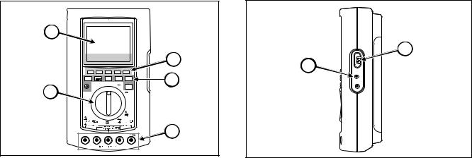
Figure 1-1. Graphical Multimeter Features
G
F
rita0092.eps
Figure 1-2. RS232 and AC Power Connections
1-1

867B/863
Users Manual
|
|
Table 1-1. Introducing Your Graphical Multimeter |
|
|
|
|
|
ITEM |
SYMBOL |
DESCRIPTION |
|
|
|
|
|
A |
j |
TURN THE GMM ON BY ROTATING THE SELECTOR TO ANY FUNCTION. Turn the rotary |
|
selector to the AC Volts (v) position. The input connections screen appears for a few seconds, |
|||
|
|||
|
then the screen sets up for this function, and you are ready to begin. You can toggle the backlight |
||
|
|
power level (Model 867B only) by pressing W. Also note that the screen goes dark if you do not |
|
|
W |
change any controls for about 20 minutes and the GMM is on battery power; pressing Wwakes |
|
|
up the screen (all models.) |
||
B |
Combo |
THE SCREEN. In AC Volts, the initial screen presents a primary display of large digits, a |
|
secondary display of smaller digits, and a graphical window showing either a waveform or an |
|||
|
|
||
|
Meter |
analog NeedleGraphä representation of the primary display. In addition, the upper screen line |
|
|
View |
displays status information. The bottom screen line (immediately above the softkey labels) shows |
|
|
the display mode, range, and other information. For example, “Combo” appears on this line if a |
||
|
|
||
|
Trend |
waveform appears in the graphical window: the GMM is in Combo Mode. |
|
C |
1 |
THE SOFTKEYS. Most control settings (selector change or key press) change the softkey labels |
|
|
2 |
along the bottom of the screen. These labels define the present uses for the five blue keys that |
|
|
are positioned immediately below the screen. Together, the labels and the keys form a set of |
||
|
3 |
Softkeys. These changing softkey definitions allow direct access to a wealth of GMM capabilities. |
|
|
4 |
Refer to Figures 1-6, 1-7, and 1-8 at the end of this chapter for a roadmap to softkey use. |
|
|
5 |
|
1-2
|
|
|
A Quick Tour |
1 |
|
|
|
|
Your Graphical Multimeter |
||
|
|
|
Table 1-1. Introducing Your Graphical Multimeter (cont) |
|
|
|
|
|
|
|
|
|
ITEM |
SYMBOL |
DESCRIPTION |
|
|
|
|
|
|
|
|
|
D |
d |
THE HARDKEYS. Hardkeys appear immediately below the softkeys. Hardkeys perform the same |
|
|
|
|
F |
operations in all functions. Pressing Wwakes up the screen from Sleep Mode (all models) and toggles |
|
|
|
|
P |
the backlight power level on Model 867B. Although hardkeys can generally be pressed at any time, |
|
|
|
|
certain feature combinations are not allowed. The GMM test tool rejects any hardkey press that is not |
|
|
|
|
|
M |
allowed; a long beep sounds. Chapter 4 explains each hardkey in detail. |
|
|
|
|
r |
|
|
|
|
|
H |
|
|
|
|
E |
V |
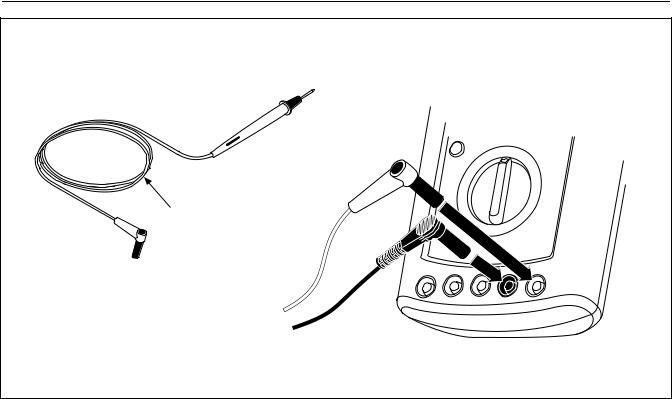
MEASUREMENT CONNECTIONS. Review the input connection scheme now only for |
|
|
|
|
C |
familiarization: no actual connections are necessary during the Quick Tour. Volts, Ohms, |
|
|
|
|
Continuity, Conductance, Diode Test, Capacitance, and Component Test measurements use |
|
|
|
|
|
X |
Vfor the Red lead. Amps measurements use Afor the Red lead. mAµA measurements |
|
|
|
|
use afor the Red lead. LOGIC Test measurements use Xfor the Red lead. All |
|
|
|
|
|
A |
functions use Cfor the Black lead. Refer to Figure 1-3 for TL70A test lead connection |
|
|
|
|
a |
|
|
|
|
|
|
views. |
|
|
|
F |
B |
LINE POWER OR BATTERY POWER. You can power the GMM with batteries or from ac line |
|
|
|
|
|
power through the Battery Eliminator. New alkaline (AA) cells provide a minimum of 4 hours |
|
|
|
|
|
operation. A fully charged BP7217 NiCd battery pack typically provides a minimum of 8 hours |
|
|
|
|
|
operation. The battery eliminator recharges the NiCd battery pack on Model 867B. Refer to |
|
|
|
|
|
Figure 1-4. |
|
|
|
|
|
|
|
|
|
G |
RS232 |
SERIAL PC OR PRINTER CONNECTION. Your GMM can use an optional optical serial |
|
|
|
interface cable to communicate with a PC or printer. Refer to Chapter 6. |
|
|
||
|
|
|
|
|
|
|
|
|
|
|
|
1-3
867B/863
Users Manual
TL70A
Test Leads
rita0740.eps
Figure 1-3. Test Leads and Measurement Connections
1-4

A Quick Tour |
1 |
Your Graphical Multimeter |
Europe PN 942602 |
AU NZ |
UK PN 942607 |
US PN 942599 |
|
PN 944595 |
|
JP PN 942610 |
|
|
|
rita0770.eps |
Figure 1-4. Using the Battery Eliminator
1-5

867B/863
Users Manual
|
|
Table 1-2. A Practice Session |
|
|
|
STEP |
ACTION |
DESCRIPTION |
|
|
|
1 |
d |
CHANGE THE DISPLAY MODE |
|
|
With the GMM still in AC Volts, press first d, then 3to change the display mode. The |
|
|
screen changes to the View Mode, where the entire screen is used for displaying a waveform. |
|
|
You can repeat this procedure to select any of the display modes available in AC Volts (Combo, |
|
|
Meter, View, and Trend.) Refer to Table 1-3 for an overview of display modes available in each |
|
|
function. Examples of all display modes (Combo, Meter, View, Trend, Logic Test, Auto Diode |
|
|
Test, Component Test, and Sleep) follow this table. Along with the flexibility provided by multiple |
|
|
softkey definitions, display modes increase the versatility of your GMM considerably. |
|
|
Many operations activated in one display mode are retained when you select a new mode. For |
|
|
example, “Rel”, “dB”, Min Max, range, and frequency measurement type are retained. |
|
|
|
2 |
J |
CHANGE THE FUNCTION |
Rotate the selector to DC Volts (E). Observe that the display shifts back to Combo Display Mode. |
||
|
|
(This is the default mode, as established on the screen you see when you turn the selector to |
|
|
SET UP.) |
|
|
|
3 |
1 |
USE THE SOFTKEYS |
|
|
With DC Volts and Combo Mode still active, you can use the DC Volts Softkeys. For example, |
|
|
press 1to activate “Rel”: difference readings only are now displayed. Press 1 again to |
|
|
deactivate “Rel”. Explore all five softkeys in this fashion. Press a key first to activate a selection |
|
|
(label highlighted) and second to disable the selection. |
|
|
|
1-6
|
|
|
|
A Quick Tour |
1 |
|
|
|
|
Your Graphical Multimeter |
|
|
|
|
Table 1-2. A Practice Session (cont) |
|
|
|
|
|
|
|
|
|
STEP |
ACTION |
|
DESCRIPTION |
|
|
|
|
|
|
|
|
4 |
r |
CHANGE THE MEASUREMENT RANGE |
|
|
|
|
|
Press rto access the Range Softkeys, then press 2to select a higher range (and activate |
||
|
|
|
“Manual” ranging.) |
Press 1to switch back to “Auto” ranging, then press rto return to the |
|
|
|
|
DC Volts Softkeys. |
|
|
|
|
|
|
|
|
|
5 |
M |
ENABLE MIN MAX READINGS |
|
|
|
|
|
Press Mto start displaying the maximum (“Max”), average (“Avg”), and minimum (“Min”) |
|
|
|
|
|
readings. Press Magain to deactivate Min Max. |
|
|
|
6 |
H |
ENABLE TOUCH HOLD |
|
|
|
|
|
Press Hto begin holding the last valid reading in the display, even if the test leads are |
|
|
|
|
|
withdrawn from the measurement point. happears in the upper status line. Press Hagain to |
|
|
|
|
|
stop Touch Hold |
|
|
|
|
|
|
|
|
|
7 |
F |
CHANGE THE TYPE OF FREQUENCY DISPLAY |
|
|
|
|
|
Press Fto access the Frequency Softkeys. |
|
|
|
|
|
The frequency reading (which was in the secondary display) and DC Volts reading (which was in |
||
|
|
|
the primary display) are swapped. |
|
|
|
|
|
The softkeys allow you to select different types of frequency measurements (Hz, Duty Cycle, |
|
|
|
|
|
Pulse Width, or Period). Press 4to select “Period”, then press Fagain to return to the DC |
||
|
|
|
Volts Softkeys. Primary and secondary displays swap again, and the change to “Period” frequency |
||
|
|
|
measurement continues in the secondary display. |
|
|
|
|
|
|
|
|
1-7

867B/863
Users Manual
|
|
Table 1-2. A Practice Session (cont) |
|
|
|
STEP |
ACTION |
DESCRIPTION |
|
|
|
8 |
P |
LOOK AT THE SAVE/PRINT SOFTKEYS |
|
|
Press Pto access the Save/Print Softkeys. You can now use the softkeys to exercise various |
|
|
save, recall, and print features. Refer to Chapter 6 for more information. (Waveform save/recall is |
|
|
not available on Model 863.) |
|
|
|
9 |
o |
TURN THE GMM OFF |
About This Manual
This Quick Tour has introduced you to all the features necessary to use your GMM. If you are comfortable with this level of information, continue on to Chapter 2 for specific information keyed to each type of measurement. If you want more information about any of the features, refer to Chapters 3 through 8, as follows:
∙Chapter 3: General descriptions of the GMM controls, screen, and input connections.
∙Chapter 4: Complete instructions for using the hardkeys (d F P M r H).
1-8
∙Chapter 5: View Mode and Trend Mode, in detail.
∙Chapter 6: Save, Recall, and Print using P and Configuration Changes using SET UP.
∙Chapter 7. User Maintenance (battery and fuse replacement, etc.)
∙Chapter 8: Specifications
∙Index
A Quick Tour
Combo Mode 1
Combo Mode
Combo |
Meter |
View |
Trend |
Exit |
Combo Mode presents both digital and graphical views of the measurement and can be used in VAC, VDC, mV DC, Amps, and mAµA functions. Combo is the default mode in these functions.
Meter Mode
Combo |
Meter |
View |
Trend |
Exit |
Meter Mode presents both a digital reading and an analog position indication of the measurement. You can select Meter in VAC, VDC, mV DC, Ohms, Amps, and mAµA functions; you can also set Meter on the SET UP screen as the default mode in these functions.
Meter is the only mode available in Diode and Capacitance Test.
View Mode
Combo |
Meter |
View |
Trend |
Exit |
View Mode displays a full-screen waveform. It is available in VAC, VDC, mV DC, Amps, and mAµA functions.
Trend Mode
Combo |
Meter |
View |
Trend |
Exit, |
Trend Mode presents a digital reading of the measurement and plots that reading over time. It is available in VAC, VDC, mV DC, Ohms, Amps, and mAµA functions.
1-9
867B/863
Users Manual
Auto Diode Test Mode |
|
Component Test Mode |
|||||||||||
|
|
Comp. |
|
|
|
|
|||||||
|
|
|
|
|
|
|
|
|
|
|
|
|
|
|
|
Meter |
|
|
|
Exit |
|
|
|
|
|||
|
|
|
|
|
|
|
Test |
|
|
|
Exit |
||
|
|
|
|
|
|
|
|
|
|
|
|
||
|
|
|
|
Auto Diode Test presents a DC |
|
|
|
|
Component Test displays a |
||||
|
|
|
|
|
|
|
|
||||||
|
|
|
|
voltage reading and a symbol |
|
|
|
|
unique pattern representing the |
||||
|
|
|
|
representing the state of the |
|
|
|
|
characteristics of the in-circuit |
||||
|
|
|
|
diode (forward, reverse, open, |
|
|
|
|
component being tested. This |
||||
|
|
|
|
short, unknown.) |
|
|
|
|
signature can resemble a |
||||
|
|
|
|
|
|
|
|
|
|
|
straight line for purely resistive |
||
|
|
|
|
|
|
|
|
|
|
|
components or an ellipsoid for |
||
|
|
|
|
|
|
|
|
|
|
|
|||
|
|
|
|
|
|
|
|
frequency-sensitive components. |
|||||
Logic Test Mode |
|
|
Sleep Mode |
||||
|
Logic |
|
|
|
Exit |
|
|
|
|
|
|
|
|
|
|
Logic Test shows icons representing high and/or low logic state along with frequency and voltage readings of logic activity.
W restores the screen.
Sleep Mode comes on automatically during battery operation if you do not press a key or turn the selector for approximately 20 minutes.
1-10

A Quick Tour
Sleep Mode 1
Table 1-3. Functions and Display Modes
|
|
|
|
|
|
|
FUNCTION |
|
|
|
|
|
Lc |
|
|||
|
v |
|
E |
|
e |
|
R |
|
D |
|
I |
|
i |
|
|
||
|
|
|
|
|
|
|
|
|
|||||||||
Combo |
∙ |
|
∙ |
|
∙ |
|
|
|
|
|
∙ |
|
∙ |
|
|
|
|
|
|
|
|
|
|
|
|
|
|
|
|
|
|
|
|
|
|
Meter |
∙ |
|
∙ |
|
∙ |
|
∙ |
|
∙ |
|
∙ |
|
∙ |
|
|
|
|
|
|
|
|
|
|
|
|
|
|
|
|
|
|
|
|
|
|
View |
∙ |
|
∙ |
|
∙ |
|
|
|
|
|
∙ |
|
∙ |
|
|
|
|
|
|
|
|
|
|
|
|
|
|
|
|
|
|
|
|
|
|
Trend |
∙ |
|
∙ |
|
∙ |
|
∙ |
|
|
|
∙ |
|
∙ |
|
|
|
|
|
|
|
|
|
|
|
|
|
|
|
|
|
|
|
|
|
|
Auto Diode |
|
|
|
|
|
|
|
|
∙ |
|
|
|
|
|
|
|
|
|
|
|
|
|
|
|
|
|
|
|
|
|
|
|
|
|
|
Logic |
|
|
|
|
|
|
|
|
|
|
|
|
|
|
∙ |
|
|
|
|
|
|
|
|
|
|
|
|
|
|
|
|
|
|
|
|
Comp.Test |
|
|
|
|
|
|
|
|
|
|
|
|
|
|
|
∙ |
|
|
|
|
|
|
|
|
|
|
|
|
|
|
|
|
|
|
|
1-11
867B/863
Users Manual
|
Combo |
Meter |
View |
Trend |
Exit |
DISPLAY |
||
|
MODE |
|||||||
|
|
|
|
|
|
|
|
|
|
|
|
|
|
|
|
|
|
Rel |
Peak |
rms |
dB |
Full |
|
Hold |
Average |
150Ω |
Auto |
Rel |
|
Peak |
DC & |
dB |
Full |
|
|
|
|||
|
|
Hold |
AC rms |
150Ω |
Auto |
|
|
|
|||
|
|
|
|
|
|
|
|
|
|
|
|
|
|
|
|
|
|
|
|
|
|
|
|
|
|
|
|
|
|
|
|
|
|
|
|
|
|
|
|
|
|
|
|
|
|
|
|
|
|
|
|
|
|
|
|
|
|
|
|
|
|
|
|
|
|
|
|
|
|
|
|
Rel |
|
Peak |
DC & |
dB |
|
|
|
|
|||
|
|
Hold |
AC rms |
150Ω |
Hi Z |
|
|
|
|||
|
|
|
|
|
|
|
|
|
|
|
|
Rel |
|
Peak |
DC & |
dB |
AC |
|
|
|
|||
|
|
Hold |
AC rms |
150Ω |
DC |
|
|
|
|||
|
|
|
|
|
|
|
|
|
|
|
|
Rel |
|
Peak |
rms |
dB |
|
AC |
|
|
|
||
|
|
Hold |
Average |
150Ω |
|
DC |
|
|
|
||
|
|
|
|
|
|
|
|
|
|
|
|
Rel |
|
Peak |
DC & |
mA 1Ω |
|
AC |
|
|
|
||
|
|
Hold |
AC rms |
uA 100Ω |
|
DC |
|
|
|
||
|
|
|
|
|
|
|
|
|
|
||
Rel |
|
Peak |
rms |
mA 1Ω |
AC |
|
|
|
|||
|
|
Hold |
|
Average |
uA 100Ω |
|
DC |
|
|
|
|
Enable |
|
Time |
Time |
|
|
Restart |
|||
RS232 |
|
Longer |
Shorter |
|
|
Trend |
|||
|
|
|
|
|
|
|
|
|
|
|
|
|
|
|
|
|
|
|
|
|
|
|
|
|
|
|
|
|
|
|
|
|
|
|
High |
|
|
|
|
Average |
|
Sampled |
Low |
|
|
Exit |
|||
|
Full |
|
|
|
|
|
|
|
|
|
|
|
|
|
|
|
|
||
|
Auto |
|
|
|
|
|
|
|
|
Arm
Exit
Arm
Exit
Internal
External Exit
|
Slower |
Faster |
|
Exit |
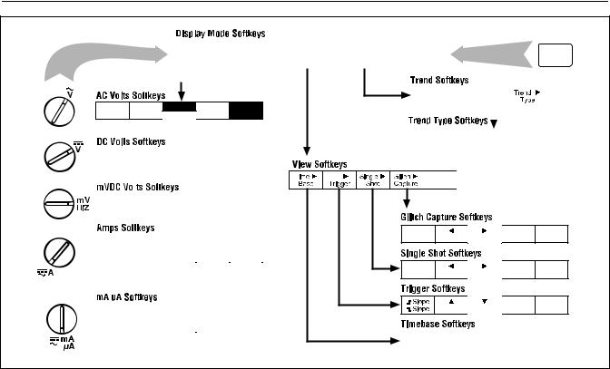
rita0330.eps
Figure 1-5. Volts and Amps Measurement Map
1-12
A Quick Tour
Sleep Mode 1
|
Meter |
|
Trend |
Exit |
|
|
|
|
|
|
|
|
|
|
|
|
|
Rel
nS
DISPLAY MODE
Enable |
Time |
Time |
|
Restart |
RS232 |
Longer |
Shorter |
|
Trend |
|
|
|
|
|
Rel
nS
Auto |
Diode |
|
|
High |
Normal |
|
Average |
Sample |
Low |
Glitch |
Exit |
Rel |
Auto |
Diode
Rel
rita0340.eps
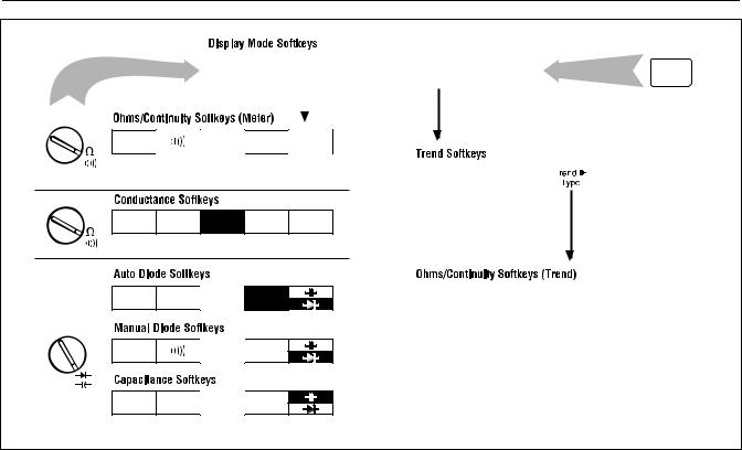
Figure 1-6. Ohms, Conductance, Diode Test, Capacitance Map
1-13
867B/863
Users Manual
|
3V |
5V |
|
|
TTL |
CMOS |
CMOS |
|
|
2 |
20 |
200 |
2 |
18.75 |
Hz |
Hz |
Hz |
kHz |
kHz |
|
Self |
|
|
|
Set Up |
Test |
|
|
Exit |
Next |
|
|
Restore |
Save |
Item |
|
|
All |
Set Up |
|
|
|
|
rita0350.eps |
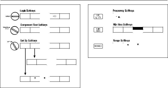
Figure 1-7. LOGIC Test, Component Test, Set Up
|
|
|
|
|
|
|
Duty |
Pulse |
|
|
|
|
|
|
|
|
|
Cycle |
Width |
Period |
Exit |
|
|
|
|
|
|
|
|
|
|
|
Min Max |
|
Run |
|
Off |
Restart |
Pause |
Exit |
Auto |
|
|
Wave |
|
Manual |
|
|
Scale |
Exit |
rita0360.eps
Figure 1-8. Hz Min Max, and Range Map
1-14
Chapter 2
Making Measurements
Note
Recharge the NiCd battery pack before using the 867B. See Battery Considerations in Chapter 3.
Introduction
This chapter shows overall procedures for making measurements in any of the rotary selector positions. Necessary input connections are shown. Softkeys used with each of the display modes available for the selected function are also shown.
Using the Selector
To begin using the GMMä, turn the selector to any of the indicated functions. Softkey labels momentarily identify the display modes available for this function, then proceed to list the softkeys available with this function.
Softkeys
Any selector setting or hardkey press provides you with a unique set of softkey labels along the bottom
of the display. These labels define the present uses for the five blue keys that are positioned immediately below the display.
In Combo and Meter display modes, some labels are used with several different selector positions; see Table 2-1 for descriptions of these common labels. Other labels are unique for the selector position; these labels are defined in this chapter as needed.
View and TrendGraphä softkey labels are common for all functions that can use these modes; refer to Chapter 5 for a full discussion.
Hardkeys
Although hardkeys can generally be pressed at any time, certain feature combinations are not allowed. The GMM rejects any hardkey press that is not allowed and tells you so with a long beep.
2-1

867B/863
Users Manual
|
|
Table 2-1. Common Combo/Meter Mode Softkeys |
|
|
|
|
|
KEY |
FUNCTION |
DESCRIPTION |
|
|
|
|
|
1 |
Rel |
Start relative readings in the primary display (REL is displayed). The relative reference (stored |
|
when “Rel” is selected) appears with the softkey. |
|||
|
|
||
|
|
|
|
2 |
Peak |
Peak Hold displays the highest and lowest peak values encountered in the present measurement |
|
function. These values replace either the secondary reading in Meter Mode or the graphical |
|||
|
Hold |
||
|
display in Combo Mode. |
||
|
|
||
|
|
|
|
3 |
rms |
Toggle between true “rms” (“rms” annunciator on in display) and “Average” (average responding, |
|
rms indicating - no annunciator) readings in any ac function. The rms/Average selection remains |
|||
|
Average |
||
|
in effect until you change the selector position. The rms/Average settings made in one display |
||
|
|
||
|
|
mode are automatically made for other display modes in the same selector position. “Average” or |
|
|
|
“rms” can be set as the standard selection on the SET UP display. |
|
|
|
|
|
3 |
DC & |
In VDC or mV DC, use the full display to show the numerical “DC” and “AC rms” values. Press |
|
3again to return to the original display. |
|||
|
AC rms |
||
|
|
|
|
4 |
dB |
Show dBm values in the primary display. The “dB” value shown above this softkey identifies the |
|
|
|
||
|
|
resistance used in computing dBm; 600Ω is the standard value. You can change this value from |
|
|
|
the SET UP display. (Rotate the selector to SET UP, change the reference selection, then rotate |
|
|
|
the selector back to the original ac function.) |
|
|
|
|
2-2
|
|
|
Making Measurements |
2 |
|
|
|
Introduction |
|
|
|
|
Table 2-1. Common Combo/Meter Mode Softkeys (cont) |
|
|
|
|
|
|
|
KEY |
FUNCTION |
DESCRIPTION |
|
|
|
|
|
|
5 |
Full |
The GMM automatically selects range, trigger level, and time base (in VAC and VDC for an |
|
|
|
|
Auto |
optimum display. If “Manual” is selected for Range in the SET UP screen, “Full Auto” does not |
|
|
|
|
come on. Selecting “Manual” from the Range Softkeys deselects “Full Auto”. |
|
|
|
|
|
|
5 |
Hi Z |
Enter the high input impedance mode in mV DC. “Hi-Z” appears at the top of the display. Press |
||
|
|
|
again to return to “mV”. Activating “DC & AC rms” automatically cancels “Hi-Z”. You cannot use |
|
|
|
|
Peak Hold with HiZ. |
|
|
|
|
|
|
5 |
AC |
Toggle between “DC” and “AC” amps or mAµA measurements. “DC” is the standard |
|
|
|
|
DC |
configuration. |
|
|
|
|
|
|
4 |
/ |
Activate the beeper for continuity or Manual Diode testing; a beep then sounds each time the |
|
|
|
|
|
voltage drop passes below 0.7V (Continuity) or the logic activity indicator flashes (LOGIC |
|
|
|
|
Testing). A short circuit results in a continuous tone. If the reading goes above 30 volts, a |
|
|
|
|
possibly dangerous voltage exists on the inputs but is not displayed. Therefore, the safety |
|
|
|
|
indicator (l) lights. |
|
2-3
867B/863
Users Manual
|
|
|
|
|
3 |
|
1 |
2 |
3 |
4 |
5 |
4 |
|
Circuit |
||||||
|
|
FREEZE |
|
|
||
DISPLAY |
HZ |
SAVE |
MIN |
|
RANGE |
|
MODE |
|
MAX |
|
|||
|
|
|
||||
|
|
|
V |
|
TOUCH |
|
|
|
|
|
HOLD |
||
WAKE UP |
|
|
|
|
|
|
|
|
|
|
|
1 |
|
|
|
|
|
|
2 |
|
A |
mA /A EXT TRIG COM |
V |
|
|||
|
|
|
|
|
Red |
|
|
|
|
|
|
rita0550.eps |
|
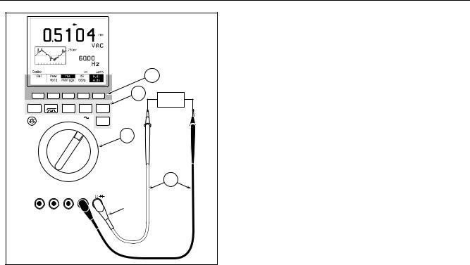
Measuring AC Volts
6Turn the Selector to Volts AC. Display mode softkeys appear momentarily; press a softkey to select a new mode, or wait briefly to accept the presently highlighted selection.
7Connect the test leads as shown.
8Use the AC Volts Softkeys as discussed below.
9All hardkeys are available in Volts AC.
At any time, press dand one of the softkeys (Combo, Meter, View, or Trend) to show the measurement in a different display mode.
Figure 2-1. AC Volts Measurements
2-4

Making Measurements 2
Measuring AC Volts
Using the AC Volts Softkeys
Combo or Meter Mode: refer to Table 2-1.
Rel |
Peak |
|
rms |
|
dB |
Full |
|
Hold |
|
Average |
600Ω |
Auto |
|
View Mode: refer to Chapter 5.
Time > |
> |
Single > |
Glitch > |
Full |
Base |
Trigger |
Shot |
Capture |
Auto |
Trend Mode: refer to Chapter 5.
Enable |
Time |
Time |
Trend > |
Restart |
RS232 |
Longer |
Shorter |
Type |
Trend |
2-5
 Loading...