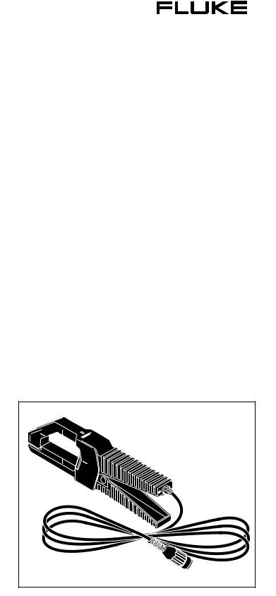
Fluke 80I-500S User Manual

®
80i-500s
AC CURRENT PROBE FOR OSCILLOSCOPES
Instruction Sheet
INTRODUCTION
The Fluke 80i-500s is a clamp-on current probe that is designed to reproduce current waveforms found in modern commercial and industrial power distribution systems. The probe’s performance is optimized for accurate reproduction of currents at line frequency and up to the 50th harmonic. The 80i-500s is also compatible with any instrument capable of millivolt measurements.
∙Ideal for measuring distorted current waveforms and associated harmonics.
∙Allows measurement of currents from 1 to 500A ac rms, 5 Hz to 10 kHz without breaking into the circuit.
∙Provides an output of 1 mV ac per 1 amp ac.
∙A passive filter eliminates noise and ring on rapidly rising waveforms, ensuring accurate reproduction on oscilloscope displays.
∙Rated for 600V circuits of Overvoltage Category III per IEC 1010-1. (See “Safety Specifications” for an explanation of Overvoltage Categories.)
WWARNING
Read “Safety Information” Before using the probe.
Figure 1. 80i-500s AC Current Probe
PN 936922
January 1994
©1994 Fluke Corporation. All rights reserved. Printed in U.S.A.
All product names are trademarks of their respective companies.

BOX CONTENTS
The shipping container includes the 80i-500s Current Probe, this Instruction Sheet, a Quick Reference Card, and a product registration card.
SAFETY INFORMATION
Read the following safety information carefully before attempting to operate or service the current probe.
∙W Never use the probe on circuits rated higher than 600V in Overvoltage Category III (CAT III) or 300V in Overvoltage Category IV (CAT IV) of IEC-1010-1. (See “Safety Specifications”.) Use extreme caution when clamping around uninsulated conductors or bus bars.
∙Keep your fingers behind the finger guard.
∙Check magnetic mating surface of the probe jaws; these should be free of dust, dirt, rust, and other foreign matter.
∙Do not use a probe that is cracked, damaged, or has a defective cable. Such probes should be made inoperative by taping the clamp shut to prevent operation.
In this instruction sheet, a WARNING identifies conditions and actions that pose hazards to the user. A Caution identifies conditions and actions that may damage the current probe. International electrical symbols used are explained in Figure 2.
B |
AC-ALTERNATING |
W |
CAUTION see |
|
CURRENT |
|
explanation in |
|
|
|
manual |
D |
Either DC or AC |
T |
Equipment protected |
|
|
|
throughout by |
|
|
|
DOUBLE |
|
|
|
INSULATION or |
|
|
|
REINFORCED |
|
|
|
INSULATION |
J |
EARTH |
|
|
Figure 2. International Electrical Symbols
The 80i-500s complies with IEC Publication 1010-1 and other safety standards (see “Safety Specifications”). Follow all warnings to ensure safe operation.
Use of this equipment in a manner not specified herein may impair the protection provided by the equipment.
SAFETY SPECIFICATIONS
WRated for 600V ac circuits of Overvoltage Category III per IEC 1010-1 and 300V ac circuits of Overvoltage Category IV per IEC 1010-1.
Overvoltage (Installation) Category III refers to distribution level and fixed installation circuits inside a building electrical service entrance. Overvoltage (Installation) Category IV refers to primary supply, overhead lines, and cable systems outside a building.
Designed to Protection Class II, double or reinforced insulation requirements of UL 1244, ANSI / ISA S82, CSA-C22.2 No. 1010. 1-92, and IEC 1010-1.
ELECTRICAL SPECIFICATIONS
Current Range: 1A to 500A ac rms.
AC Current Over Range Limit: Up to 700A ac rms for maximum of 10 minutes, followed by removal from current carrying conductor for at least 30 minutes.
Output Signal: 1 mV ac/A ac
Influence of Temperature on Accuracy: <0.15% per 10°C (18°F) for temperatures from -10 to 18°C (14 to 64°F) and from 28 to 50°C (82 to 122°F).
Basic Accuracy (45 to 65 Hz):
Input Current: |
Error: |
Phase Shift: |
1 to 20A |
5% of rdg + 0.3A |
Not Specified |
20 to 100A |
5% of rdg |
±3° |
100 to 500A |
2% of rdg |
±1° |
Extended Accuracy:
For other frequencies, refer to the appropriate input current range and add the error listed below to the “Basic Accuracy” error.
Input Current: Error:
(5 to 10 Hz): |
1 to 500A |
not specified* |
(10 to 20 Hz): |
1 to 300A |
5% |
|
300 to 400A |
15% |
|
400 to 500A |
25% |
(20 to 45 Hz): |
1 to 500A |
5% |
(65 Hz to 3 kHz): |
1 to 50A |
5%+0.4A |
|
50 to 500A |
5% |
(3 kHz to 10 kHz): |
1 to 500A |
not specified* |
*-3 db @ 5 Hz and 10 kHz typical
Input Load Impedance (of host instrument): >1MΩ in parallel with up to 47 pF
dV/dt max: 0.24 mV/μsec
Rise or Fall Time: <40 μsec
WWorking Voltage: 600V ac rms, in compliance with IEC-1010-1.
WCommon Mode Voltage: 600V ac rms from earth ground, in compliance with IEC 1010-1.
Influence of Adjacent Conductor: <5 mA/A
Influence of Conductor Position in Jaw Opening: +/-(1.5% of reading +0.1A).
GENERAL SPECIFICATIONS
Dimensions: |
66 x 195 x 34 mm (2.6 x 7.7 x 1.3 in.) |
Weight: |
420g (14.8 oz.) |
Temperature: |
Operating: -10 to 50°C (14 to 122°F) |
|
Storage: -40 to 71°C (-40 to 160°F) |
Relative Humidity: |
0 to 95% (10 to 30°C; 50 to 86°F) |
|
0 to 75% (30 to 40°C; 86 to 104°F) |
|
0 to 45% (40 to 50°C; 104 to 122°F) |
Altitude: |
non-operating: 0 to 12000 meters (0 |
|
to 39370 ft.) operating: 0 to 2000 |
|
meters (0 to 6560 ft.) |
 Loading...