


 Loading...
789/787B
ProcessMeter™
Users Manual
August 2002, Rev. 4, 1/17
© 2002-2017 Fluke Corporation. All rights reserved. Specifications are subject to change without notice. All product names are trademarks of their respective companies.
LIMITED WARRANTY AND LIMITATION OF LIABILITY
This Fluke product will be free from defects in material and workmanship for three years from the date of purchase. This warranty does not cover fuses, disposable batteries, or damage from accident, neglect, misuse, alteration, contamination, or abnormal conditions of operation or handling. Resellers are not authorized to extend any other warranty on Fluke’s behalf. To obtain service during the warranty period, contact your nearest Fluke authorized service center to obtain return authorization information, then send the product to that Service Center with a description of the problem.
THIS WARRANTY IS YOUR ONLY REMEDY. NO OTHER WARRANTIES, SUCH AS FITNESS FOR A PARTICULAR PURPOSE, ARE EXPRESSED OR IMPLIED. FLUKE IS NOT LIABLE FOR ANY SPECIAL, INDIRECT, INCIDENTAL OR CONSEQUENTIAL DAMAGES OR LOSSES, ARISING FROM ANY CAUSE OR THEORY. Since some states or countries do not allow the exclusion or limitation of an implied warranty or of incidental or consequential damages, this limitation of liability may not apply to you.
Fluke Corporation |
Fluke Europe B.V. |
P.O. Box 9090 |
P.O. Box 1186 |
Everett, WA 98206-9090 |
5602 BD Eindhoven |
U.S.A. |
The Netherlands |
11/99
Table of Contents
Title |
Page |
Introduction .................................................................................................................... |
1 |
How to Contact Fluke ..................................................................................................... |
2 |
Safety Information .......................................................................................................... |
2 |
How to Get Started......................................................................................................... |
6 |
Getting Acquainted with the Meter ................................................................................. |
7 |
Measuring Electrical Parameters.................................................................................... |
18 |
Input Impedance........................................................................................................ |
18 |
Ranges ...................................................................................................................... |
18 |
Testing Diodes........................................................................................................... |
18 |
Displaying Minimum, Maximum, and Average........................................................... |
19 |
Using AutoHold.......................................................................................................... |
19 |
Compensating for Test Lead Resistance................................................................... |
20 |
Using the Current Output Functions ............................................................................... |
20 |
Source Mode ............................................................................................................. |
20 |
Simulate Mode........................................................................................................... |
22 |
Producing a Steady mA Output ................................................................................. |
24 |
Manually Stepping the mA Output ............................................................................. |
25 |
Auto Ramping the mA Output.................................................................................... |
26 |
i

789/787B
Users Manual
Power-Up Options ......................................................................................................... |
26 |
Loop Power Supply Mode (789 only)............................................................................. |
28 |
Battery Life..................................................................................................................... |
30 |
Maintenance .................................................................................................................. |
30 |
Calibration................................................................................................................. |
31 |
Replacing the Batteries ............................................................................................. |
31 |
Replacing a Fuse ...................................................................................................... |
33 |
If the Meter does not Work........................................................................................ |
34 |
Replacement Parts and Accessories ............................................................................. |
34 |
Specifications................................................................................................................. |
38 |
ii
Introduction
Warning
Read “Safety Information” before using the meter.
The Fluke 789/787B ProcessMeter (the Meter or Product) is a handheld, battery-operated tool for measuring electrical parameters and supplying steady or ramping current to test process instruments. All illustrations in this manual show the 789 model.
The 789 adds a 24 V loop power supply. It has all the features of a digital multimeter, plus current output capability.
ProcessMeter
If the meter is damaged or something is missing, contact the place of purchase immediately. Contact a Fluke distributor for information about DMM (digital multimeter) accessories. To order replacement parts or spares, see Table 13 near the end of this manual.
1

789/787B
Users Manual
How to Contact Fluke
To contact Fluke, call one of the following telephone numbers:
•Technical Support USA: 1-800-44-FLUKE (1-800-443-5853)
•Calibration/Repair USA: 1-888-99-FLUKE (1-888-993-5853)
•Canada: 1-800-36-FLUKE (1-800-363-5853)
•Europe: +31 402-675-200
•Japan: +81-3-6714-3114
•Singapore: +65-6799-5566
•Anywhere in the world: +1-425-446-5500
Or, visit Fluke's website at www.fluke.com.
To register your product, visit http://register.fluke.com.
To view, print, or download the latest manual supplement, visit http://us.fluke.com/usen/support/manuals.
Safety Information
A Warning identifies conditions and procedures that are dangerous to the user. A Caution identifies conditions and procedures that can cause damage to the Product or the equipment under test.
International symbols used on the meter and in this manual are explained in Table 1.
Warning
To prevent possible electrical shock, fire, or personal injury:
•Read all safety information before you use the Product.
•Carefully read all instructions.
•Do not alter the Product and use only as specified, or the protection supplied by the Product can be compromised.
•Remove the batteries if the Product is not used for an extended period of time, or if stored in temperatures above 50 °C. If the batteries are not removed, battery leakage can damage the Product.
2

ProcessMeter™
Safety Information
•The battery door must be closed and locked before you operate the Product.
•Replace the batteries when the low battery indicator shows to prevent incorrect measurements.
•Comply with local and national safety codes. Use personal protective equipment (approved rubber gloves, face protection, and flameresistant clothes) to prevent shock and arc blast injury where hazardous live conductors are exposed.
•Do not apply more than the rated voltage, between the terminals or between each terminal and earth ground.
•Do not work alone.
•Limit operation to the specified measurement category, voltage, or amperage ratings.
•Use Product-approved measurement category (CAT), voltage, and amperage rated accessories (probes, test leads, and adapters) for all measurements.
•Measure a known voltage first to make sure that the Product operates correctly.
•Use the correct terminals, function, and range for measurements.
•Do not touch voltages > 30 V ac rms, 42 V ac peak, or 60 V dc.
•Do not use the Product around explosive gas, vapor, or in damp or wet environments.
•Do not use the Product if it operates incorrectly.
•Examine the case before you use the Product. Look for cracks or missing plastic. Carefully look at the insulation around the terminals.
•Do not use test leads if they are damaged. Examine the test leads for damaged insulation, exposed metal, or if the wear indicator shows. Check test lead continuity.
3

789/787B
Users Manual
•Keep fingers behind the finger guards on the probes.
•Only use probes, test leads, and accessories that have the same measurement category, voltage, and amperage ratings as the Product.
•Remove all probes, test leads, and accessories before the battery door is opened.
•Remove all probes, test leads, and accessories that are not necessary for the measurement.
•Do not exceed the Measurement Category (CAT) rating of the lowest rated individual component of a Product, probe, or accessory.
•Do not use test leads if they are damaged. Examine the test leads for damaged insulation and measure a known voltage.
•Do not use a current measurement as an indication that a circuit is safe to touch. A voltage measurement is necessary to know if a circuit is hazardous.
•Do not use the Product if it is altered or damaged.
•Do not use in CAT III or CAT IV environments without the protective cap installed on test probe. The protective cap decreases the exposed probe metal to <4 mm. This decreases the possibility of arc flash from short circuits.
4

|
|
|
|
ProcessMeter™ |
|
|
|
|
Safety Information |
|
|
|
|
|
|
|
Table 1. International Symbols |
|
|
|
|
|
|
|
|
Symbol |
Description |
Symbol |
Description |
|
|
|
|
WARNING. HAZARDOUS VOLTAGE. Risk |
|
|
WARNING. RISK OF DANGER. |
|
|
|
of electric shock. |
|||
|
|
|||
|
|
|
|
StandardsConforms to relevant South Korean EMC |
|
|
Consult user documentation. |
|
|
|
|
Conforms to European Union directives |
|
Minimum fuse interrupt rating. |
|
|
|
|
|
|
|
Certified by CSA Group to North American safety |
|
Conforms to relevant Australian Safety and |
|
standards. |
EMC standards. |
||
|
|
|
|
|
|
|
AC (Alternating Current) |
|
Earth |
|
|
DC (Direct Current) |
|
Fuse |
|
|
|
|
|
|
|
Battery |
|
Double Insulated |
Measurement Category II is applicable to test and measuring circuits connected directly to utilization points (socket outlets and similar points) of the low-voltage MAINS installation.
Measurement Category III is applicable to test and measuring circuits connected to the distribution part of the building’s low-voltage MAINS installation.
Measurement Category IV is applicable to test and measuring circuits connected at the source of the building’s low-voltage MAINS installation.
This product complies with the WEEE Directive marking requirements. The affixed label indicates that you must not
discard this electrical/electronic product in domestic household waste. Product Category: With reference to the equipment types in the WEEE Directive Annex I, this product is classed as category 9 "Monitoring and Control Instrumentation" product. Do not dispose of this product as unsorted municipal waste.
5

789/787B
Users Manual
How to Get Started
Warning
To prevent possible electrical shock, fire, or personal injury:
•Disconnect power and discharge all highvoltage capacitors before you measure resistance, continuity, capacitance, or a diode junction.
•Remove circuit power before you connect the Product in the circuit when you measure current. Connect the Product in series with the circuit.
•Do not use the HOLD function to measure unknown potentials. When HOLD is turned on, the display does not change when a different potential is measured.
If familiar with the Fluke 80 Series DMM, read “Using the Current Output Functions,” review the tables and figures in “Getting Acquainted with the Meter,” and begin using the meter.
If unfamiliar with Fluke 80 Series DMMs, or DMMs in general, read “Measuring Electrical Parameters” in addition to the sections referenced in the previous paragraph.
The sections following “Using the Current Output Functions” contain information about the power-up options, and battery and fuse replacement instructions.
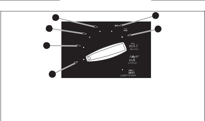
See Table 2 for an overview of the meter.
6
|
ProcessMeter™ |
|
Getting Acquainted with the Meter |
|
|
Table 2. 789/787B ProcessMeter |
Getting Acquainted with the Meter |
1
3 |
0%
2
4 |
anw014f.eps
Item |
Description |
|
Display |
|
|
|
Rotary switch |
|
|
|
Pushbuttons |
|
|
|
Input/Output jacks |
|
|
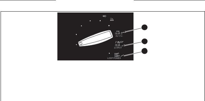
To become familiar with the features and functions of the meter, study these tables:
•Table 3 describes the input/output jacks.
•Table 4 describes the input functions of the first six rotary function switch positions.
•Table 5 describes the output functions of the last three rotary function switch positions.
•Table 6 describes the functions of the pushbuttons.
•Table 7 explains what all the elements of the display indicate.
7

789/787B
Users Manual
Table 3. Input/Output Jacks
A |
mA |
COM |
V |
1 |
|
|
|
2 |
4 |
3 |
anw001f.eps
Item |
Jack |
Measurement Functions |
|
Source Current Function |
|
Simulate Transmitter Function |
|
|
|
|
|
|
|
|
|
Input for current to 440 mA |
|
Output for dc current to 24 |
|
|
|
A c |
continuous. (1 A for up to |
|
|
|
|
|
|
mA. Output for loop power |
|
|
||
30 seconds.) Fused with a |
|
|
|
|||
|
|
|
supply (789 only). |
|
|
|
|
|
440 mA fuse. |
|
|
|
|
|
|
|
|
|
|
|
|
mA d |
Input for current to 30 mA. |
|
Common for dc current output |
|
Output for transmitter simulation to |
|
|
to 24 mA. Common for loop |
|
24 mA. (Use in series with an |
||
Fused with a 440 mA fuse. |
|
|
||||
|
|
|
|
power supply. |
|
external loop supply.) |
|
V |
Input for voltage to 1000 V, Ω, |
|
|
|
|
continuity, and diode test. |
|
|
|
|
||
|
|
|
|
|
||
|
COM |
|
|
|
|
Common for transmitter simulation |
|
Common for all measurements. |
|
|
|
to 24 mA. (Use in series with an |
|
|
|
|
|
|
|
external loop supply.) |
|
|
|
|
|
|
|
8
ProcessMeter™
Getting Acquainted with the Meter
Table 4. Rotary Function Switch Positions for Measurements
4 |
5 |
|
3 |
6 |
2 |
1
anw002f.eps
No. |
Position |
Function(s) |
|
Pushbutton Actions |
|
|
|
|
|
|
OFF |
Meter off |
|
|
|
|
Default: |
|
MSelects a MIN, MAX, or AVG action |
|
|
Measure ac V |
|
RSelects a fixed range (hold 1 second for auto range) |
|
S |
h |
|
|
|
HToggles AutoHold |
|||
|
|
Frequency counter |
|
|
|
|
|
rToggles relative reading (sets a relative zero point) |
|
|
|
|
|
9

789/787B
Users Manual
Table 4. Rotary Function Switch Positions for Measurements (cont.)
No. |
Position |
Function(s) |
Pushbutton Actions |
|
|
|
|
|
|
Default: |
Same as above |
|
T |
Measure dc V |
|
|
|
||
|
|
h |
|
|
|
Frequency counter |
|
|
|
Default: |
Same as above (mV has only one range) |
|
|
hMeasure dc mV |
|
|
U |
|
|
|
|
Frequency counter |
|
|
|
|
|
|
|
Default: Measure Ω |
Same as above (diode test has only one range) |
|
V |
Gfor continuity |
|
|
|
J(Blue) Dtest |
|
|
|
|
|
|
|
High test lead in cA: Measure |
Same as above (only one range for each input jack position, |
|
|
A dc |
30 mA or 1 A) |
|
W |
J(Blue) selects ac |
|
|
|
High test lead in dmA: |
|
|
|
Measure mA dc |
|
10
ProcessMeter™
Getting Acquainted with the Meter
Table 5. Rotary Function Switch Positions for mA Output
1 |
2 |
3 |
|
|
|
anw008f.eps |
|
|
|
|
|
|
No. |
Position |
Default Function |
Pushbutton Actions |
|
|
|
|
|
|
|
|
Test leads in |
% STEP Xor W: Adjusts output up or down to the next 25 % step |
|
|
OUTPUT |
SOURCE: |
COARSE Xor W: Adjusts output up or down 0.1 mA |
|
|
Source 0 % mA |
FINE Xor W: Adjusts output up or down 0.001 mA |
||
X |
||||
|
|
Test leads in SIMULATE: |
sets output to 0 % |
|
|
|
Sink 0 % mA |
sets output to 100 % |
|
|
|
|
11
Loading...