


 Loading...
9103
Dry-Well
User’s Guide
PN 2673813
March 2013
© 2013 Fluke Corporation. All rights reserved. Specifications are subject to change without notice. All product names are trademarks of their respective companies.

Table of Contents
1 Before You Start . . . . . . . . . . . . . . . . . . . . . . . . . . 1
1.1 |
Symbols Used . . . . . . . . . . . . . . . . . . . . . . . . . . . . 1 |
1.2Safety Information . . . . . . . . . . . . . . . . . . . . . . . . . . 2
1.2.1 Warnings . . . . . . . . . . . . . . . . . . . . . . . . . . . . . . . . . . . . . 2
1.2.2 Cautions . . . . . . . . . . . . . . . . . . . . . . . . . . . . . . . . . . . . . 3
1.3Authorized Service Centers. . . . . . . . . . . . . . . . . . . . . . 3
2Introduction . . . . . . . . . . . . . . . . . . . . . . . . . . . . 7
3Specifications and Environmental Conditions . . . . . . . . . . 9
3.1Specifications . . . . . . . . . . . . . . . . . . . . . . . . . . . . . 9
3.2Environmental Conditions . . . . . . . . . . . . . . . . . . . . . . 9
3.3Warranty. . . . . . . . . . . . . . . . . . . . . . . . . . . . . . . 10
4Quick Start . . . . . . . . . . . . . . . . . . . . . . . . . . . . 11
4.1Unpacking . . . . . . . . . . . . . . . . . . . . . . . . . . . . . . 11
4.2Setup. . . . . . . . . . . . . . . . . . . . . . . . . . . . . . . . . 11
4.3Power . . . . . . . . . . . . . . . . . . . . . . . . . . . . . . . . 11
4.4Setting the Temperature . . . . . . . . . . . . . . . . . . . . . . . 12
5Parts and Controls . . . . . . . . . . . . . . . . . . . . . . . . 13
5.1Back Panel. . . . . . . . . . . . . . . . . . . . . . . . . . . . . . 13
5.2 |
Front Panel . . . . . . . . . . . . . . . . . . . . . . . . . . . . . 13 |
5.3Constant Temperature Block Assembly . . . . . . . . . . . . . . . 15
5.4Probe Sleeves . . . . . . . . . . . . . . . . . . . . . . . . . . . . 15
6General . . . . . . . . . . . . . . . . . . . . . . . . . . . . . . 17
6.1Changing Display Units . . . . . . . . . . . . . . . . . . . . . . . 17
6.2Thermal Electric Devices (TED) . . . . . . . . . . . . . . . . . . 17
7Controller Operation . . . . . . . . . . . . . . . . . . . . . . . 19
7.1Well Temperature . . . . . . . . . . . . . . . . . . . . . . . . . . 19
7.2Temperature Set-point . . . . . . . . . . . . . . . . . . . . . . . . 19
7.2.1 Programmable Set-points . . . . . . . . . . . . . . . . . . . . . . . . . . . . 19
7.2.2 Set-point Value . . . . . . . . . . . . . . . . . . . . . . . . . . . . . . . . . 21
7.2.3 Temperature Scale Units . . . . . . . . . . . . . . . . . . . . . . . . . . . . 21
i
7.3Scan . . . . . . . . . . . . . . . . . . . . . . . . . . . . . . . . . 22
|
7.3.1 |
Scan Control . . . . . . . |
. . . . . . . . . . . . . . . . . . . . . . . . . . . 22 |
|
7.3.2 |
Scan Rate . . . . . . . . . |
. . . . . . . . . . . . . . . . . . . . . . . . . . . 22 |
7.4 |
Temperature Display Hold |
. . . . . . . . . . . . . . . . . . . . . 22 |
|
7.4.1 Enabling the Hold Temperature Display . . . . . . . . . . . . . . . . . . . . 23 7.4.2 Mode Setting . . . . . . . . . . . . . . . . . . . . . . . . . . . . . . . . . . 23 7.4.3 Switch Wiring . . . . . . . . . . . . . . . . . . . . . . . . . . . . . . . . . . 23 7.4.4 Switch Test Example . . . . . . . . . . . . . . . . . . . . . . . . . . . . . . 24
7.5Set-point Resistance . . . . . . . . . . . . . . . . . . . . . . . . . 24
7.6 |
Temperature Scale Units . . . . . . . . . . . . . . . . . . . . . . 24 |
7.7Secondary Menu. . . . . . . . . . . . . . . . . . . . . . . . . . . 24
7.8Thermal Electric Devices (TED) . . . . . . . . . . . . . . . . . . 25
7.9Proportional Band . . . . . . . . . . . . . . . . . . . . . . . . . . 25
7.10Controller Configuration . . . . . . . . . . . . . . . . . . . . . . 26
7.11Operating Parameters . . . . . . . . . . . . . . . . . . . . . . . . 26
7.12Serial Interface Parameters . . . . . . . . . . . . . . . . . . . . . 27
7.12.1 BAUD Rate . . . . . . . . . . . . . . . . . . . . . . . . . . . . . . . . . . . 27 7.12.2 Sample Period. . . . . . . . . . . . . . . . . . . . . . . . . . . . . . . . . . 28 7.12.3 Duplex Mode . . . . . . . . . . . . . . . . . . . . . . . . . . . . . . . . . . 28 7.12.4 Linefeed . . . . . . . . . . . . . . . . . . . . . . . . . . . . . . . . . . . . . 28
7.13 Calibration Parameters . . . . . . . . . . . . . . . . . . . . . . . 29
7.13.1 R0 . . . . . . . . . . . . . . . . . . . . . . . . . . . . . . . . . . . . . . . . 29 7.13.2 ALPHA . . . . . . . . . . . . . . . . . . . . . . . . . . . . . . . . . . . . . 29 7.13.3 DELTA . . . . . . . . . . . . . . . . . . . . . . . . . . . . . . . . . . . . . 30 7.13.4 BETA . . . . . . . . . . . . . . . . . . . . . . . . . . . . . . . . . . . . . . 30
8 Digital Communication Interface . . . . . . . . . . . . . . . . 31
8.1Serial Communications . . . . . . . . . . . . . . . . . . . . . . . 31
|
8.1.1 |
Wiring . . . . . . . |
. . . . . . . . . . . . . . . . . . . . . . . . . . . . . . . 31 |
|
|
8.1.2 |
Setup . . . . . . . . |
. . . . . . . . . . . . . . . . . . . . . . . . . . . . . . 31 |
|
|
|
8.1.2.1 |
BAUD Rate . . . . |
. . . . . . . . . . . . . . . . . . . . . . . . . . . . . . . . . . . 32 |
|
|
8.1.2.2 |
Sample Period. . . |
. . . . . . . . . . . . . . . . . . . . . . . . . . . . . . . . . . . 32 |
|
|
8.1.2.3 |
Duplex Mode . . . |
. . . . . . . . . . . . . . . . . . . . . . . . . . . . . . . . . . . 32 |
|
|
8.1.2.4 |
Linefeed . . . . . . |
. . . . . . . . . . . . . . . . . . . . . . . . . . . . . . . . . . . 32 |
|
8.1.3 |
Serial Operation . . . |
. . . . . . . . . . . . . . . . . . . . . . . . . . . . . . 33 |
|
8.2 |
Interface Commands |
. . . . . . . . . . . . . . . . . . . . . . . . 33 |
||
9Test Probe Calibration . . . . . . . . . . . . . . . . . . . . . . 37
9.1Calibrating a Single Probe. . . . . . . . . . . . . . . . . . . . . . 37
9.2Stabilization and Accuracy . . . . . . . . . . . . . . . . . . . . . 37
10 Calibration Procedure . . . . . . . . . . . . . . . . . . . . . . 39
10.1Calibration Points . . . . . . . . . . . . . . . . . . . . . . . . . . 39
10.2Calibration Procedure . . . . . . . . . . . . . . . . . . . . . . . . 39
ii
10.2.1 Compute DELTA . . . . . . . . . . . . . . . . . . . . . . . . . . . . . . . . 39 10.2.2 Compute R0 and ALPHA. . . . . . . . . . . . . . . . . . . . . . . . . . . . 40 10.2.3 Compute BETA . . . . . . . . . . . . . . . . . . . . . . . . . . . . . . . . . 41 10.2.4 Accuracy and Repeatability. . . . . . . . . . . . . . . . . . . . . . . . . . . 41
11 Maintenance . . . . . . . . . . . . . . . . . . . . . . . . . . . 43 12 Trouble Shooting . . . . . . . . . . . . . . . . . . . . . . . . . 45
12.1Troubleshooting . . . . . . . . . . . . . . . . . . . . . . . . . . . 45
12.2CE Comments . . . . . . . . . . . . . . . . . . . . . . . . . . . . 46
12.2.1 EMC Directive . . . . . . . . . . . . . . . . . . . . . . . . . . . . . . . . . 46 12.2.2 Low Voltage Directive (Safety) . . . . . . . . . . . . . . . . . . . . . . . . . 46
iii
Figures
Figure 1 |
9103 Back Panel . . . . . . . . . . . . . . . . . . . . . . . . . . . . . |
14 |
Figure 2 |
9103 Front Panel . . . . . . . . . . . . . . . . . . . . . . . . . . . . . |
15 |
Figure 3 |
Inserts Available for the 9103 Block Assembly . . . . . . . . . . . . . |
16 |
Figure 4 |
Controller Operation Flowchart . . . . . . . . . . . . . . . . . . . . . |
20 |
Figure 5 |
Serial Cable Wiring . . . . . . . . . . . . . . . . . . . . . . . . . . . |
31 |
iv
Tables
Table 1 |
International Electrical Symbols . . . . . . . . . . . . . . . . . . . . . |
1 |
Table 2 |
9103 Controller Communications Commands . . . . . . . . . . . . . . |
34 |
Table 2 |
Table 2 9103 Controller Communications Commands continued . . . . |
35 |
v

1 Before You Start
Symbols Used
1Before You Start
1.1Symbols Used
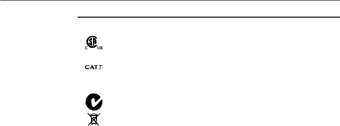
Table 1 lists the International Electrical Symbols. Some or all of these symbols may be used on the instrument or in this manual.
Table 1 International Electrical Symbols
Symbol |
Description |
||||||||
|
|
|
|
|
|
|
|
|
|
|
|
|
|
|
|
|
|
|
AC (Alternating Current) |
|
|
|
|
|
|
|
|
|
AC-DC |
|
|
|
|
|
|
|
|
|
Battery |
|
|
|
|
|
|
|
|
|
|
|
|
|
|
|
|
|
|
|
CE Complies with European Union Directives |
|
|
|
|
|
|
|
|
|
DC |
|
|
|
|
|
|
|
|
|
|
|
|
|
|
|
|
|
|
|
Double Insulated |
|
|
|
|
|
|
|
|
|
|
|
|
|
|
|
|
|
|
|
|
|
|
|
|
|
|
|
|
|
Electric Shock |
|
|
|
|
|
|
|
|
|
|
|
|
|
|
|
|
|
|
|
Fuse |
|
|
|
|
|
|
|
|
|
PE Ground |
|
|
|
|
|
|
|
|
|
|
|
|
|
|
|
|
|
|
|
|
|
|
|
|
|
|
|
|
|
Hot Surface (Burn Hazard) |
|
|
|
|
|
|
|
|
|
|
|
|
|
|
|
|
|
|
|
Read the User’s Manual (Important Information) |
|
|
|
|
|
|
|
|
|
Off |
|
|
|
|
|
|
|
|
|
On |
|
|
|
|
|
|
|
|
|
|
|
|
|
|
|
|
|
|
|
|
1
9103 Dry-Well
User’s Guide
Symbol |
Description |
|
|
|
|
|
|
Canadian Standards Association |
|
|
OVERVOLTAGE (Installation) CATEGORY II, Pollution Degree 2 per IEC1010-1 re- |
|
|
fers to the level of Impulse Withstand Voltage protection provided. Equipment of |
|
|
OVERVOLTAGE CATEGORY II is energy-consuming equipment to be supplied from |
|
|
the fixed installation. Examples include household, office, and laboratory appliances. |
|
|
C-TIC Australian EMC Mark |
|
|
The European Waste Electrical and Electronic Equipment (WEEE) Directive |
|
|
(2002/96/EC) mark. |
|
|
|
1.2Safety Information
Use this instrument only as specified in this manual. Otherwise, the protection provided by the instrument may be impaired.
The following definitions apply to the terms “Warning” and “Caution”.
•“Warning” identifies conditions and actions that may pose hazards to the user.
•“Caution” identifies conditions and actions that may damage the instrument being used.
1.2.1 Warnings
To avoid personal injury, follow these guidelines.
BURN HAZARD – DO NOT touch the well access surface of the unit. The temperature of the well access is the same as the actual temperature shown on the display. If the instrument is set at 140°C and the display reads 140°C, the well is at 140°C.
DO NOT remove inserts at high temperatures. Inserts are the same temperature as the display temperature. Use extreme care when removing hot inserts.
DO NOT operate this unit without a properly grounded, properly polarized power cord.
DO NOT connect this unit to a non-grounded, non-polarized outlet.
HIGH VOLTAGE is used in the operation of this equipment. SEVERE INJURY OR DEATH may result if personnel fail to observe safety precautions. Before working inside the equipment, turn the power off and disconnect the power cord.
Always replace the fuse with one of the same rating, voltage, and type.
Overhead clearance is required. DO NOT place this instrument under a cabinet or other structure.
2
1 Before You Start
Authorized Service Centers
DO NOT use this unit for any application other than calibration work.
DO NOT use this unit in environments other than those listed in the user’s guide.
DO NOT turn the unit upside down with the inserts in place; the inserts will fall out of the unit.
DO NOT operate near flammable materials.
Use of this instrument at HIGH TEMPERATURES for extended periods of time requires caution.
Completely unattended high temperature operation is not recommended for safety reasons.
Before initial use, after transport, and anytime the dry-well has not been energized for more than 10 days, the calibrator must be energized for a dry-out period of 1 to 2 hours before it can be assumed to meet all of the safety requirements of the IEC1010-1.
Follow all safety guidelines listed in the user’s manual. Calibration equipment should only be used by Trained Personnel.
1.2.2 Cautions
To avoid possible damage to the instrument, follow these guidelines.
•Components and heater lifetime can be shortened by continuous high temperature operation.
•Allow for test probe expansion inside the well as the dry-well heats.
•DO NOT use fluids to clean out the well.
•Never introduce foreign material into the probe hole of the insert. Fluids, etc. can leak into the calibrator causing damage.
•DO NOT change the values of the calibration constants from the factory set values. The correct setting of these parameters is important to the safety and proper operation of the calibrator.
•DO NOT slam the probe stems into the well. This type of action can cause a shock to the sensor and affect the calibration.
•DO use a ground fault interrupt device.
1.3Authorized Service Centers
Please contact one of the following authorized Service Centers to coordinate service on your Hart product:
Fluke Corporation, Hart Scientific Division
799 E. Utah Valley Drive
3

9103 Dry-Well
User’s Guide
American Fork, UT 84003-9775
USA
Phone: +1.801.763.1600
Telefax: +1.801.763.1010
E-mail: support@hartscientific.com
Fluke Nederland B.V.
Customer Support Services
Science Park Eindhoven 5108
5692 EC Son
NETHERLANDS
Phone: +31-402-675300
Telefax: +31-402-675321
E-mail: ServiceDesk@fluke.nl
Fluke Int'l Corporation
Service Center - Instrimpex
Room 2301 Sciteck Tower
22 Jianguomenwai Dajie
Chao Yang District
Beijing 100004, PRC
CHINA
Phone: +86-10-6-512-3436
Telefax: +86-10-6-512-3437
E-mail: xingye.han@fluke.com.cn
Fluke South East Asia Pte Ltd.
Fluke ASEAN Regional Office Service Center
60 Alexandra Terrace #03-16 The Comtech (Lobby D) 118502
SINGAPORE
Phone: +65 6799-5588
4

1 Before You Start
Authorized Service Centers
Telefax: +65 6799-5588 E-mail: antng@singa.fluke.com
When contacting these Service Centers for support, please have the following information available:
•Model Number
•Serial Number
•Voltage
•Complete description of the problem
5

2 Introduction
2Introduction
The Hart Scientific 9103 Dry-well may be used as a portable instrument or bench top temperature calibrator for calibration thermocouples and RTD temperature probes. The 9103 is small enough to use in the field and accurate enough to use in the lab. With an ambient temperature of 23°C (74°F), calibrations may be done over a range of –25°C to 140°C (–13°F to 284°F). The resolution of the 9103 temperature display is 0.1 degrees.
The calibrator features:
•Convenient handle
•RS-232 interface
•Universal AC input
Built in programmable features include:
•Temperature scan rate control
•Temperature switch hold
•Eight set-point memory
•Adjustable readout in °C or °F
The temperature is accurately controlled by Hart’s hybrid analog/digital controller. The controller uses a precision platinum RTD as a sensor and controls the well temperature with pulsed driven Thermal Electric Devices (TED).
The LED display panel continuously shows the current well temperature. The temperature may be easily set with the control buttons to any desired temperature within the specified range. The calibrator’s multiple fault protection devices insure user and instrument safety and protection.
The 9103 Dry-well was designed for portability, low cost, and ease of operation. Through proper use, the instrument will continuously provide accurate calibration of temperature sensors and devices. The user should be familiar with the safety guidelines and operating procedures of the calibrator as described in this user manual.
7

3 Specifications and Environmental Conditions
Specifications
3Specifications and Environmental Conditions
3.1 |
Specifications |
|
|
|
|
|
Operating Range |
–25°C to 140°C (–13°F to 284°F), at 23°C ambient |
|
Accuracy |
±0.25°C (±1.0°C in holes > ¼” [6.4 mm]) |
|
Stability |
±0.02°C at –25°C |
|
|
±0.04°C at 140°C |
|
Well-to-Well Uniformity |
±0.1 with similar probes |
|
Resolution |
0.1°C or °F |
|
Display Scale |
°F or °C, switchable |
|
Thermal Electric Devices (TED) |
150 W |
|
Heating Time |
18 minutes from ambient to 140°C |
|
Cooling Time |
20 minutes from ambient to –25°C |
|
Stabilization Time |
7 minutes |
|
Immersion Depth |
4.875 inches (124 mm) |
|
Power Requirements |
115 VAC (±10%), 1.3 A or 230 VAC (±10%) 0.7 A, switchable, 50/60 |
|
|
Hz, 150W |
|
Inserts |
A, B, or C |
|
Computer Interface |
RS-232 included with free Interface-it Software (Model 9930) |
|
Size |
10.25” H x 5.63” W x 9.63” D |
|
|
(26.1 x 14.3 x 24.5 cm) |
|
Weight |
12 lb. (5.7 kg) |
|
|
|
3.2 Environmental Conditions
Although the instrument has been designed for optimum durability and trou- ble-free operation, it must be handled with care. The instrument should not be operated in an excessively dusty or dirty environment. Maintenance and cleaning recommendations can be found in the Maintenance Section of this manual.
The instrument operates safely under the following conditions:
• temperature range: 5–45°C (41–113°F)
• ambient relative humidity: 15 - 50%
• pressure: 75kPa - 106kPa
• mains voltage within ± 10% of nominal
• vibrations in the calibration environment should be minimized
• altitude less than 2,000 meters
9
Loading...