

Page 1
FEIYU
TECH
PANDA
GCS & AFSS AUTOPILOT SYSTEM
INSTALLATION & OPERATION MANUAL
Guilin Feiyu Electronic Technology Co., Ltd
Addr : 4th Floor,YuTaiJie Science Technology Building,Information Industry
Park , ChaoYang Road ,Qi Xing District ,Gui Lin ,541004
Website: www.feiyu-tech.com
Email: service@feiyu-tech.com
Page 2

Guilin Feiyu Electronic Technology Co., Ltd
Dear Pilot,
Thank you for purchasing the PANDA Full Function Autopilot with GCS & AFSS from FeiYu
Tech. In order to achieve full potential and safe operation of this product, please carefully read
this manual prior to installation.
Attention:
The installation and use of this autopilot require advance skill and knowledge in flying remote
controlled fixed wing aircraft, the operations of amateur autopilot system and ground control
station (GCS).
If you are a complete beginner in autopilots, we do not recommend you install this
system on your own.
Please find assistance from an experience flier who may provide you with the basic
knowledge in autopilot systems to ensure successful installation and safe use of this
device. Alternately, you may gain experience by using our PANDA first.
If you are already an experienced pilot and have used autopilot systems before, you
will find this step by step manual intuitive and logical. Just follow the instructions
as stated very carefully and you won‘t go wrong.
PANDA Autopilot: User Agreement
a) The PANDA autopilot system complies with all regulations within the People’s Republic
of China (PRC).
b) It is the end user’s responsibility to ensure compliance to regulations in their own country
if the PANDA is used outside of the PRC.
c) PANDA autopilot system is prohibited to be used for any illegal activity. It is the end
user’s responsibility to take all safety measures in using this product.
d) The Guilin Feiyu Electronic Technology Co. (herewith known as Feiyu Tech) and our
associates are not responsible for any damages or liabilities caused by the use of this
product.
e) The PANDA is internationally patented. It is unlawful to reverse engineer, copy or modify
this product in any way.
f) Feiyu Tech reserves the right to update, upgrade or modify the product at any time as we
see fit. We will to the best of our abilities inform existing users if such updates need to be
carried out in units already in use.
g) Feiyu Tech reserves the right to amend this manual and the terms and conditions of use of
the PANDA at any time.
h) By using this product you agree to these terms and conditions effective on the date of
purchase.
Please do not hesitate to e-mail us directly for assistance: service@feiyu-tech.com
Guilin Feiyu Electronic Technology Co., Ltd http://www.feiyudz.cn service@feiyu-tech.com
Page 1
Page 3
Guilin Feiyu Electronic Technology Co., Ltd
Panda Autopilot
Introduction: What it Does
PANDA is an advanced autopilot with patented Attitude Flight Stabilization System AFSS™ that
allows you to view and change in real time the flight parameters of your flying aircraft via your
Ground Control Station (GCS).
The parameters include (but are not limited to);
Waypoint setting while in flight,
Automated altitude control,
Ground speed control,
Activation of circling at given points,
Control of circling radius,
Automated Return to Home (RTH),
Automated take-off according the route setting.
Real time telemetry data transmitted to the GCS include:
Main battery voltage and mAh consumed,
GPS signal strength,
Plane attitude flight stabilization system (AFSS) status,
All parameters as shown on the On Screen Display (OSD)
With the PANDA, autopilot flight via the GCS has never been simpler.
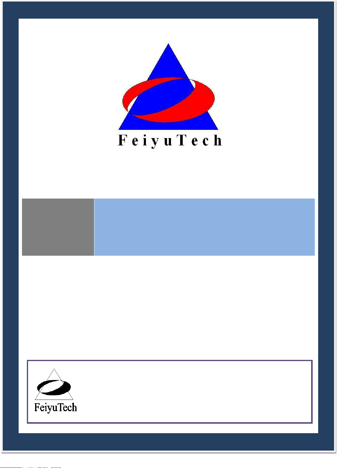
Aircraft Suitability
1. Normal / Traditional fixed-wing planes
2. Delta-winged plane with rudder
3. Delta-winged plane without rudder
4. Plane without aileron
5. V –tail plane with and without aileron
6. Any other configuration, please e-mail us for enquiry: service@feiyu-tech.com
Guilin Feiyu Electronic Technology Co., Ltd http://www.feiyudz.cn service@feiyu-tech.com
Page 2
Page 4

Guilin Feiyu Electronic Technology Co., Ltd
Major Auto Pilot Components
1. PANDA provides high-precision flight attitude measurement and control through the
utilization of an integrated 32 bits microprocessor, GPS receiver, three-axis MEMS gyros,
three-axis accelerometer, three-axis magnetic sensor, accurate barometric pressure sensor,
attitude algorithm, Kalman filtering and data fusion algorithms.
2. Combined the attitude module and the control module, get more small volume and lighter
weight.
3. Realize auto take off and auto land, maximum reduce the operating pressure.
4. Can accord to the plane internal space to adjust the install direction , easier to complete the
connection.
5. 10Hz data rate GPS receiver, 35 seconds fast positioning time and accuracy of 2.5 meters
CEP. The GPS can record the positional parameter with battery , the locating time greatly
improved.
6. 100HZ inner attitude control, 10HZ outer navigation control.
7. Multi-channel mixed-control output can be adjusted with ease. The control options include:
a) Elevator and rudder navigation
b) Elevator, aileron and rudder navigation
c) Elevator and aileron mixed-control (elevon) navigation
d) V-tail rudder may be used, however a third party mixer have to be supplied by the user.
8. Three control modes:
a) Manual Mode ;
b) AFSS activated (Active Stabilization) ;
c) Automatic navigation control.
9. Two automated navigation control modes:
a) Air route navigation mode ;
b) Mouse controlled flight mode.
10. Three special flight modes:
a) Fixed circling mode;
b) Auto Return to Home (RTH) mode;
c) Auto take-off mode.
(On Fixed circling mode and Auto Return to Home(RTH)mode,Panda has 50m altitude
protection limited,if the switch point altitude below 50m,Panda will automatic climb to 50m.)
11. Any standard RC transmitter and receiver can be used with this system.
12. Automated RTH (Return to Home) protection when there is a break in GCS communication
link via the data radios. This time the system is working only in the data radio control mode.
13. Panda can Integrated automatic and manual aerial photography triggering. Equidistance or
Timing taking photo. Combine with the POS data record module can record the current flight
attitude info of the taking photo point, for example the Longitude, latitude, altitude, speed,
etc .
14. The GCS software helps integrate Automated and Manual flight control modes in an easy to
use display interface.
15. The GCS software includes electronic map formatting. By using the electronic map, aircraft
route and tasks can be modified in real-time via your GCS computer.
Guilin Feiyu Electronic Technology Co., Ltd http://www.feiyudz.cn service@feiyu-tech.com
Page 3
Page 5

Guilin Feiyu Electronic Technology Co., Ltd
Component
Min
Value
Standard
Value
Max
Value
Units
Remark
Main Supply Voltage
4.0 5 6.5
Volt
Main Supply Current
60 mA
At 5V supply
voltage
Altitude Measurement Range
-500
6000
Meter
GPS Ground Speed Measurement
Range
0 350
Meter/Sec
GPS Horizontal Navigation
accuracy
2.5 Meter
Repeat Precision
Barometric Pressure Altitude
accuracy
2
Meter
Repeat Precision
Waypoints setting
98
98 point
programmable
Rudder Servo
3
Channel
Throttle Channel
1
Channel
Servo Output Frequency
1
µS
Updated Servo Frequency
50 Hz
Flight status PID Control Rate
100 Hz
Navigation Control PID Rate
10 HZ
Data Telemetry‘s Track Frequency
1
Hz
Maximum 10Hz
Data Telemetry‘s Mission
Frequency
1
Hz
Maximum 10Hz
Data Telemetry ‗s Flight Status
frequency
1
Hz
Maximum 10Hz
16. Real time display on the GCS includes flight parameters such as main pack voltage, mAh
consumed, Amp draw, GPS satellite strength and temperature of the autopilot unit.
17. All flight parameters are downloaded automatically by the GCS for instant playback.
18. IMPORTANT: GCS Function
When using the Data Radio to control the aircraft, the controlling signals from the RC
Receiver is directly sent to the Remote Adapter and converted to digital signals. The Data
Radio will then upload the commands to your aircraft via the data radio.
The GCS is only used to monitor telemetry and flight status of the aircraft. Transmission
of commands is minimal. i.e. the aircraft is mainly controlled by your RC Transmitter.
The autopilot still can realize most of the functions (for example, air route setting, RTH,
circling) without the GCS.
19. Support the firmware update, can update by yourself.
Technical parameters
Table 1: Unless specified, values are at operating temperature of 25 ℃.
Guilin Feiyu Electronic Technology Co., Ltd http://www.feiyudz.cn service@feiyu-tech.com
Page 4
Page 6
Guilin Feiyu Electronic Technology Co., Ltd
RS-232 Baud Rate
19200
Bps
TTL Level
Operating Temperature
-20
25
60 ℃
Temperature
25 ℃
Controller Module dimension
60×3 1×20
mm
Panda autopilot
module
Weight
35
grams
Remote Adapter Module
Dimension
52×3 1×2 0
mm
Panda remote
adapter module
Weight
27
grams
GPS Module dimension
32×32×10
mm
GPS module
Weight
21
grams
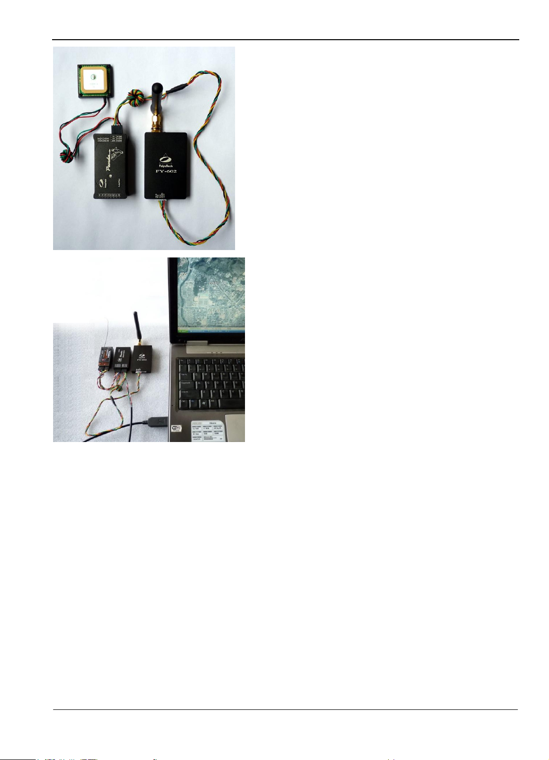
PANDA INSTALATION
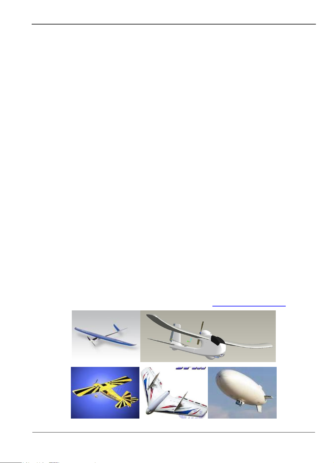
1. Before installation, please check and ensure your PANDA pack contains the following main
components:
a. Panda Autopilot module
b. Panda Remote adapter module
c. GPS module
Guilin Feiyu Electronic Technology Co., Ltd http://www.feiyudz.cn service@feiyu-tech.com
Panda AutoPilot Module
Page 5
Page 7
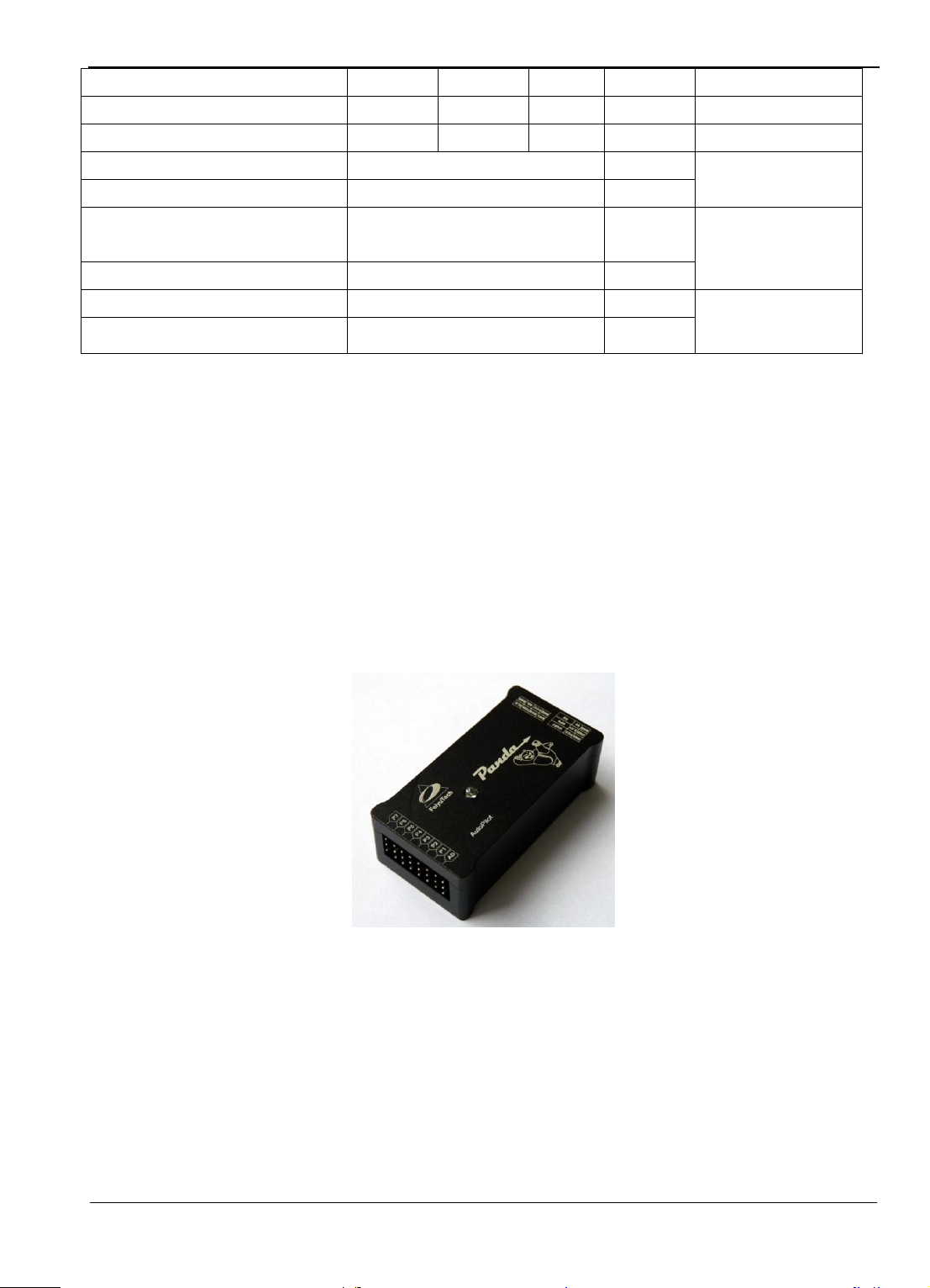
Guilin Feiyu Electronic Technology Co., Ltd
Panda Remote Adapter Module
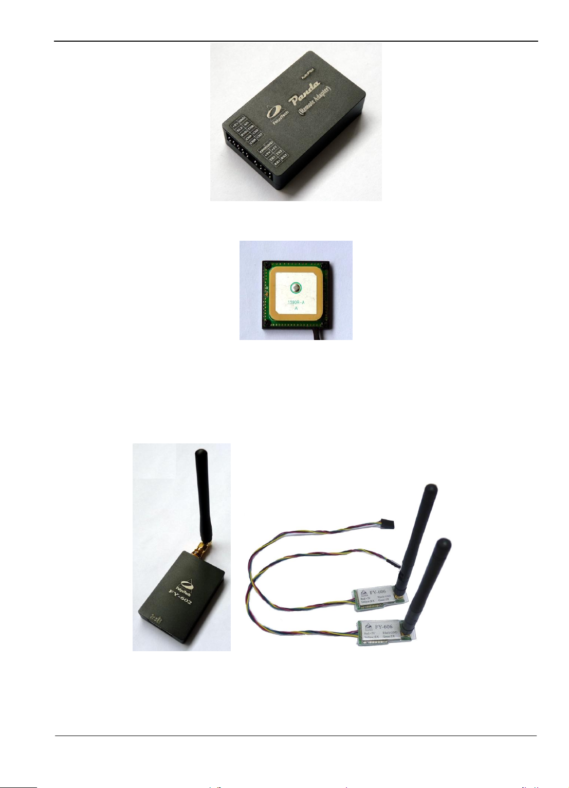
2. Optional components:
a. OSD Video overlay modules
b. Current sensor
c. Data radio module
d. Other fittings
GPS Receiver Module
FY-602Data Radio (433MHz) FY-606 Data Radio (2.4GHz)
Note: Data Radio selection please refer page 7
Guilin Feiyu Electronic Technology Co., Ltd http://www.feiyudz.cn service@feiyu-tech.com
Page 6
Page 8
Guilin Feiyu Electronic Technology Co., Ltd
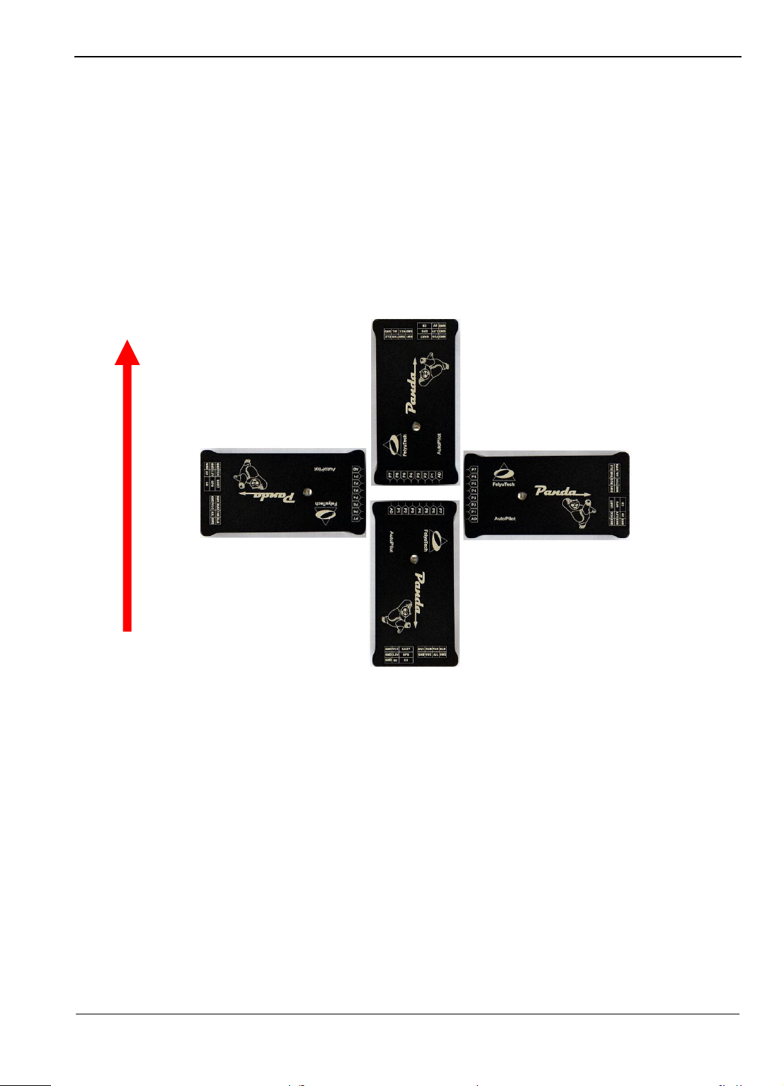
Four install directions of the Autopilot module
AutoPilot module the arrow forward(default direction)
AutoPilot module the arrow
towards to left
AutoPilot module the arrow
towards to right
AutoPilot module the arrow
towards to back
nose of the plane
FLIGHT CONTROLLER MODULE INSTALLATION
FLIGHT CONTROLLER MODULE
1. The Autopilot module must be placed horizontally and as close as possible to the plane‘s CG
(Center of Gravity). The default direction is the arrow direction must be pointing towards the
nose of the plane (i.e. direction of flight). You can change the direction to four directions via
the GCS software, i.e direction forward, back, left, right (shown below) .
2. When installing the autopilot module please make use of the supplied damper mount.
Otherwise the vibrations will cause a large data inconsistencies which will adversely affect the
autopilot accuracy.
3. PANDA autopilot integrates a GPS module including a flat-GPS passive antenna. This is a
sensitive antenna for GPS signals, while false signals reflected from the ground is effectively
filtered out. Install the GPS unit horizontally.
4. Keep metal objects and other conductive materials such as carbon fibre away from the GPS
unit. Additionally no transmitting antenna should be around the GPS antenna. The
communication link antenna (FY-606) or your video transmitter should be kept as far away
from the GPS unit as possible.
5. Radio transmissions will increase the noise signals which lead to instability in the positioning
data. The higher the radio noise, the more difficult for the GPS to lock in position.
6. PANDA can integrate with either one of Feiyu Tech‘s two Data Radio modules, the FY-606
(2.4 Ghz) or the FY-602(433 mHz).
Guilin Feiyu Electronic Technology Co., Ltd http://www.feiyudz.cn service@feiyu-tech.com
Page 7
Page 9

Guilin Feiyu Electronic Technology Co., Ltd
7. The Data Radio uplink is responsible for receiving flight navigation data from the GCS. At
the same time, the Data Radio also transmits flight status and other remote sensing
information back to the GCS. The asynchronous serial interface protocol between PANDA
autopilot and communications link is RS232-TTL level, the baud rate is 19200.
8. Place the Data Radio module as far as possible away from the GPS module, AHRS, GPS and
servos in order to avoid interference to these equipments. The Data Radio antennas should be
installed vertically upward or downward.
9. The Data Radio communication link range depends on your specific application. If your
aircraft will only be operated within a 5km radius then the FY-606 radio modem will be
sufficient. If you wish longer range then the FY-605 radio modem should be selected.
10. Also consider your Data Radio frequency selection based on your existing radio control
system, to avoid frequency interference.
11. Alternately, you can utilize your own full duplex data modem. The communication link used
by PANDA autopilot can be either a half-duplex or a full-duplex data modem.
12. Warning: Certain frequency bands from the Data Radio (e.g. 433 mHz) can interfere with
servos due to electromagnetic emission. To resolve this issue either avoid placing the Data
Radio transmitter close to sensitive components or use a magnetic core (as shown below) to
reduce the interference.
Guilin Feiyu Electronic Technology Co., Ltd http://www.feiyudz.cn service@feiyu-tech.com
Page 8
Page 10
Guilin Feiyu Electronic Technology Co., Ltd
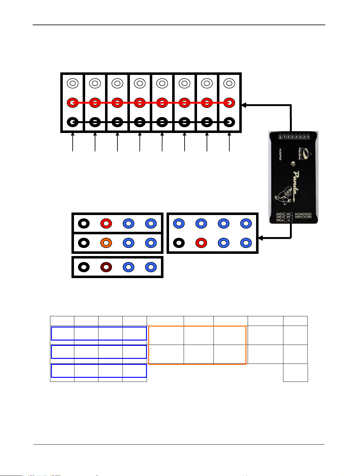
8 7 6 5 4 3 2 1 NO.
GND
VCC
TX1
RX1
Switch
input 1
Rudder
input
Throttle
input
Elevator
input
Ⅰ
GND
3.3V
TX2
RX2
GND
VCC
Aileron
input
Switch
input 2
Ⅱ
GND
5V
DL
DY Ⅲ
Signal
+5V
GND
P6
P5
P4
P3
P2
P1
AD
P7
Parachute open
OUT
External voltage
acquisition
AIL OUT
ELE OUT
THR OUT
RUD OUT
Take photo OUT
Output 1
UART port
GPS port
CS port
Receiver signal input port
Defined Interface of the PANDA Flight Controller Module
Autopilot module interface pins:
Front row pins defined:
NOTE: The pin “ Ⅱ-5,6,7,8”is for the GPS module, “Ⅱ-7”pin output +3.3V, “Ⅲ - 5,6,7,8”is
for the Current sensor , “Ⅲ - 7”pin is +5V output, please don’t supply to these pins, or will
burn the autopilot .
The output 1 is corresponding with the input of CH7 in the remote adapter.
Guilin Feiyu Electronic Technology Co., Ltd http://www.feiyudz.cn service@feiyu-tech.com
Page 9
Page 11

Guilin Feiyu Electronic Technology Co., Ltd
Name
function
UART port
Connect to the data radio
GPS port
Connect to the GPS module
CS port
Connect to the Current sensor
Receiver signal input port
Connect to channels of the receiver
AD
The external voltage acquisition port
P1
Connect to the aileron or mix-control servo 1
P2
Connect to the elevator or the mix-control servo 2
P3
Connect to the throttle or control wiring of the ESC
P4
Connect to the rudder
P5
Connect to the taking photo port of the camera
P6
Directly output the CH7 servo signal of the remote adapter module
P7
Output a servo signal which can be controlled directly by the GCS
software
Flight
mode
Auto balance
mode
Deactivated
mode
Path navigation
mode
Auto return to
home mode
(RTH)
Auto circling
mode(ACM)
LED light
indicator
Stay on solid
Continuous
flash
Continuous
flashing 3 times
each loop
Double flash
each loop
Single flash
Autopilot Module:
Serial port 1(UART port)
Baud rate: 19200
Data bits: 8
Stop bits: 1
Parity: None
TX1 connected to the RX ‗s data radio
RX1 connected to the TX ‗s data radio
Serial port 2(GPS port)
Baud rate: 38400
Data bits: 8
Stop bits: 1
Parity: None
TX2 connected to the RX ‗s GPS module
RX2 connected to the TX ‗s GPS module
Autopilot module the interface defined and function:
Autopilot module taking photo port instruction:
The P5 port of the autopilot module output a camera shutter triggered signals, this signal is TTL
level(0-3V), you can set this signal to high level trigger or low level trigger via the GCS software.
The default is high level trigger, that is in normal this output signal is low level, but when taking
photo this port will output a high level signal last for 1 second.
Autopilot Module LED indicator instruction:
Guilin Feiyu Electronic Technology Co., Ltd http://www.feiyudz.cn service@feiyu-tech.com
Page 10
Page 12
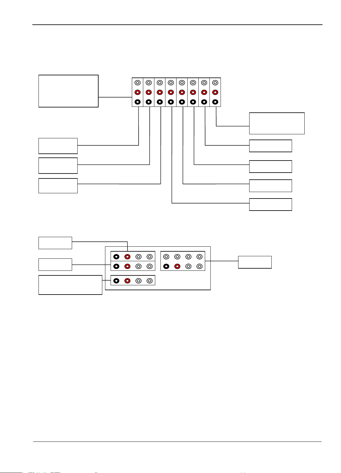
GPS
Data radio
Task servo 2
Task servo
Rudder servo
Voltage detected
(current sensor)
Aileron servo
Elevator servo
Throttle servo
VCC
GND
Receiver
External voltage
collecte
Camera
Can power up via any
free vcc port
Connection Diagram
Guilin Feiyu Electronic Technology Co., Ltd
Guilin Feiyu Electronic Technology Co., Ltd http://www.feiyudz.cn service@feiyu-tech.com
Page 11
Page 13
Guilin Feiyu Electronic Technology Co., Ltd
Name
Function
RADIO
Connect to the data radio
PC
Connect to the PC serial port
AIL
Aileron input
ELE
Elevator input
THR
Throttle input
RUD
Rudder input
CH5
Channel 5 input
CH6
Channel 6 input
CH7
Channel 7 input
CH8
Channel 8 input
+5V
GND
TX2
RX2
+5V
GND
CH5
THR
+5V
GND
AIL
CH7
ELE
RUD
CH6
CH8
TX1
RX1
RADIO
PC
Panda Remote Adapter module interface:
The CH7 of the Remote Adapter module can adapt a receiver signal to the autopilot
module, and the autopilot module output it via its P6 port.
Guilin Feiyu Electronic Technology Co., Ltd http://www.feiyudz.cn service@feiyu-tech.com
Page 12
Page 14
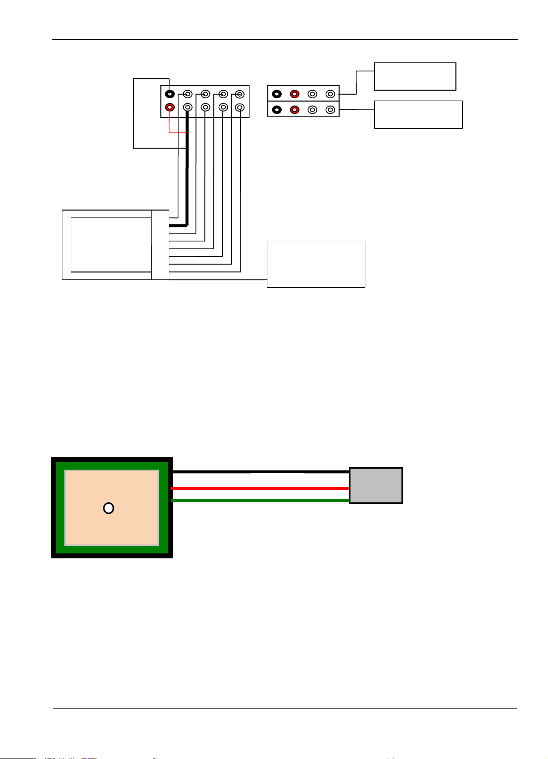
Guilin Feiyu Electronic Technology Co., Ltd
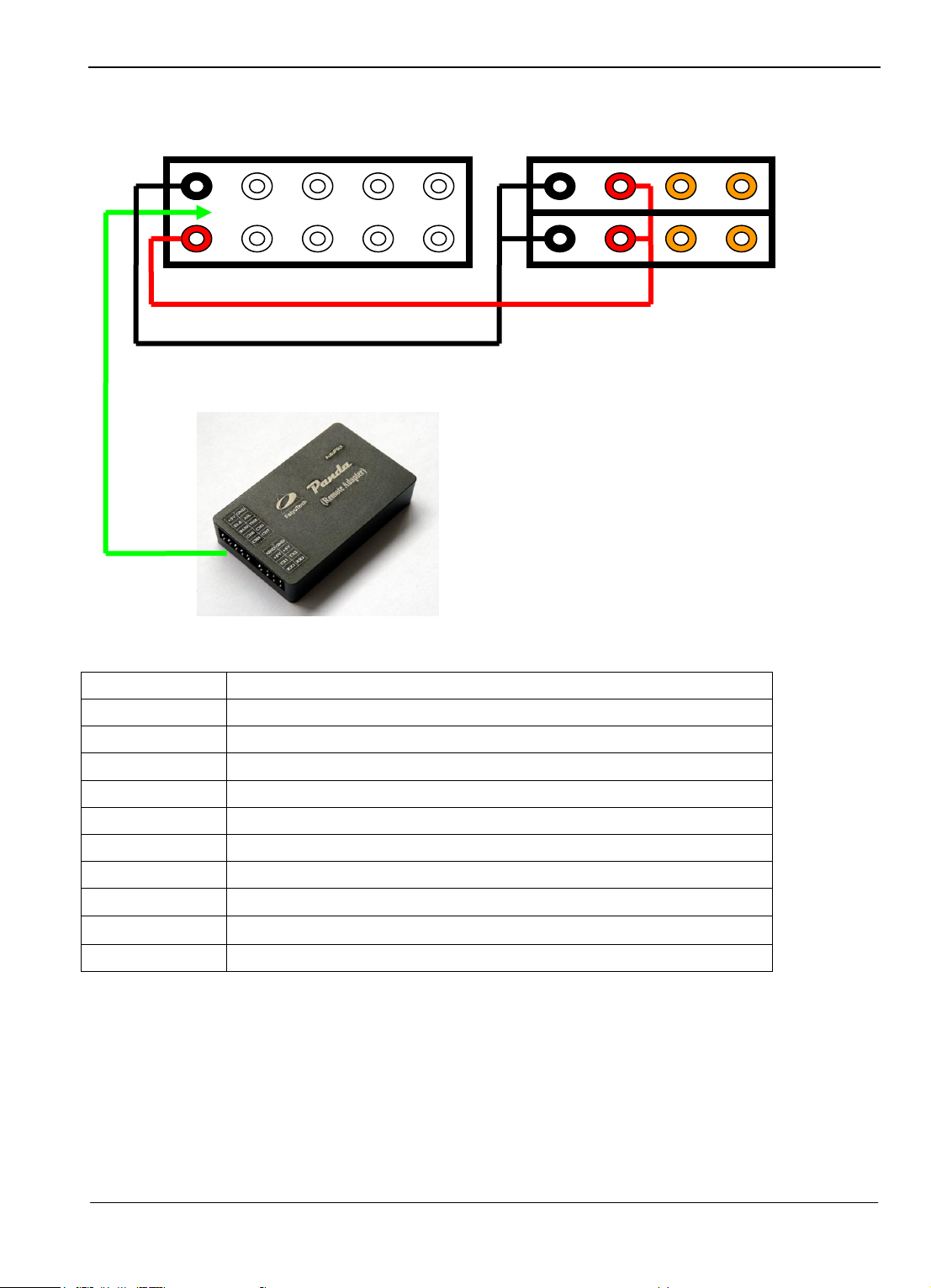
PC serial port
RC Receiver
5V battery
GND
+
Balck - -GND
Red --- +3.3V
Green —signal
Data radio
Connection Diagram
The interface and features of the GPS module
TX: For Data transmission to the Autopilot module (RX2)
RX: For Receiving data transmitted from Autopilot module (TX2)(Can disconnected )
Interface Features: TTL level
Baud rate: 38400
Data bits: 8
Stop bits: 1
Parity: None
GPS Data refresh rate: 10Hz
电流传感器:
Guilin Feiyu Electronic Technology Co., Ltd http://www.feiyudz.cn service@feiyu-tech.com
Page 13
Page 15
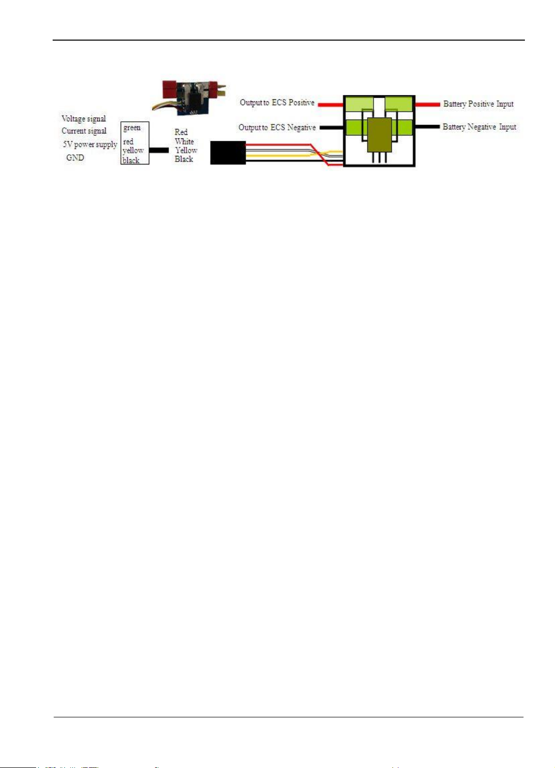
Guilin Feiyu Electronic Technology Co., Ltd
Current Sensor:
PANDA Power Supply
1. To ensure uninterrupted autopilot function, it is critical that your power system outputs a
stable and clean 5 volt power source to the PANDA system.
2. To avoid current fluctuations, ideally the power source supply to the servos should be
separate from the autopilot.
3. If the power source for the Autopilot system and servos are the same, then we highly
recommend a battery or BEC supply with higher than 3 amps output. Do check this rating
especially if you are using your ESC‘s internal BEC supply as some ESC BECs are not rated
for 3amp output.
4. We highly recommend a separate power source for the autopilot system from the receiver
and servos, as this has shown to produce the best results.
AUTOPILOT CONNECTION OPTIONS
There are three options when setting up your PANDA system. Please review them all and choose
the one that best suits your needs.
Option 1: Ground Station Controlled Flight
a) In this option, your aircraft is controlled only by the Data Radio (Figure 2). With this
setup you do not have a RC receiver in the plane (Figure 1).
Guilin Feiyu Electronic Technology Co., Ltd http://www.feiyudz.cn service@feiyu-tech.com
Page 14
Page 16
Guilin Feiyu Electronic Technology Co., Ltd
Figure 1: On the aircraft, the radio
modem controls all flight parameters.
No RC receiver is installed in your
aircraft.
Figure 2: At your ground Station, the
signals from your RC Transmitter is
sent to the RC Receiver which is
connected to your computer via the
Remote Adapter.
a) Your RC Receiver is installed at your ground station. The Receiver servo signal output is
fed into the Remote Adapter.
b) The signals received by the Remote Adapter will be converted to digital signals. The Data
Radio system then up-loads these digital commands to your aircraft.
c) The uploading of data to the aircraft does not involve the GCS. The GCS is only used to
monitor telemetry and flight status of the aircraft. GCS involvement in
fight control is minimal.
d) Warning: In Option 1, the Data Radio range will dictate your flight range. Additionally,
due to the digital signal conversion and processing, some delay in manual control
transmission will occur. Refer page 7 on notes on data transfer frequency (Hz).
Guilin Feiyu Electronic Technology Co., Ltd http://www.feiyudz.cn service@feiyu-tech.com
Page 15
Page 17

Guilin Feiyu Electronic Technology Co., Ltd
GPS module
Data radio
AIL Servo
RUD Servo
THR Servo
ELE Servo
5V servo battery
OPTION 1: ON BOARD AIRCRAFT DIAGRAMME
OPTION 1: ADVANTAGE
Option 1 will make on board installation easier since the RC Receiver does not need to be
installed on board.
You save on weight and installation area.
The entire radio and autopilot settings can be carried out at the Ground Station without
involving the aircraft.
Only a 6 channel receiver is required.
Also at least two of the channels require a three-position switch.
OPTION 1: WARNING
If you choose to use the 5.0 volt power from your ESC BEC, you can plug the throttle
OPTION 1: Activation and Deactivation of safety feature
control wire directly into the ―THR‖ port. However please ensure that your ESC internal
BEC can supply a minimum of 3.0 A current. We highly recommend that you have an
external BEC instead.
The 5.0 volt External BEC power input is connected to the +5V Pin of the P6 Port, and
the GND.
When the plane is controlled by the remote adapter board, it contains a communication
interruption protection function.
If the autopilot detects communication interruption lasting 10seconds or more, it will
enter into auto return mode and come safely home. This is the Default setting.
You can however deactivate this Safety Feature if you so wish. One reason to for
Guilin Feiyu Electronic Technology Co., Ltd http://www.feiyudz.cn service@feiyu-tech.com
Page 16
Page 18

Guilin Feiyu Electronic Technology Co., Ltd
RC Remote Receiver
AIL
USB—Serial TTL
THR
CH5
ELE
CH6
RUD
Data Radio
Receiver battery
deactivation is that the aircraft will continue flying the set route even without Data Radio
communication. This way, it can complete its flight mission fully autonomously. Of
course it would make sense to have the mission end at the base station so you won‘t lose
your plane!
RTH DeActivated:choose ― Para Settings‖ —> ― Flight Para‖, click ― RTH Deactivated‖,
when the button turn green, meaning you have set successfully. Shown as above:
OPTION 1: GROUND STATION DIAGRAMME
OPTION 1: Ground Station Requirements:
a) You will need at least a 6 channels Receiver
b) You will also need at least two, 3-position switches on your Radio Transmitter.
c) If you wish to use a 5 volt Receiver battery to power the ground station system, please
disconnect the 5 volt power coming from the USB Interface cable (picture below):
Guilin Feiyu Electronic Technology Co., Ltd http://www.feiyudz.cn service@feiyu-tech.com
Page 17
Page 19

Guilin Feiyu Electronic Technology Co., Ltd
OPTION 2: RC RECEIVER ON-BOARD
a) In Option 2, both the RC receiver and Data Radio is installed onboard the aircraft.
b) In Option 2, you have direct RC Transmitter control of the aircraft, therefore avoiding the
data transfer delays of Option 1.
c) For Option 2, you will need at least a 6 channels Receiver.
d) Two of the channels require a three-position switch. (e.g. Channel 5 and 6).
OPTION 2: ON-BOARD AIRCRAFT SYSTEM DIAGRAMME
Guilin Feiyu Electronic Technology Co., Ltd http://www.feiyudz.cn service@feiyu-tech.com
Page 18
Page 20

Guilin Feiyu Electronic Technology Co., Ltd
AIL Servo
RUD Servo
THR Servo
ELE Servo
5Vservo battery
Data radio
RC Remote Receiver
AIL
THR
CH5
ELE
CH6
RUD
GPS module
OPTION 2: POWER WARNING
If you choose to use the 5.0 volt power from your ESC BEC, you can plug the throttle
control wire directly into the ―THR‖ port. However please ensure that your ESC
internal BEC can supply a minimum of 3.0 A current.
However we highly recommend that you use an external BEC with 3.0 A current output.
The 5.0 volt External BEC power input is connected to the +5V Pin of the P6 Port, and
the GND.
OPTION 2: GROUND STATION CONTROL DIAGRAMME
Guilin Feiyu Electronic Technology Co., Ltd http://www.feiyudz.cn service@feiyu-tech.com
Page 19
Page 21

Guilin Feiyu Electronic Technology Co., Ltd
USB—Serial TTL
Data radio
NOTE: If you wish to use a 5 volt
Receiver battery to power the ground
station system, please disconnect the 5
volt power coming from the USB
Interface cable.
OPTION 3: TWO RECEIVER SYSTEM
a) Option 3 is the combination of Option 1 and Option 2.
b) In Option 3, you will require two receivers of the same frequency.
c) Ensure that both receivers can be controlled by your RC transmitter.
d) One receiver is installed on board the aircraft (as per Option 2), while the other receiver
is installed at the Ground Station (as per Option 1).
e) The Channel utilization on both the on-board receiver and Ground Station receiver must
be the same.
f) The receivers must be at least 6 channels.
g) Two of the channels require a three-position switch (e.g. Channel 5 and 6).
h) Since both systems can be used to control your aircraft, the maximum flight range is
either your RC Transmitter or the Data Radio, whichever can reach further out.But it
depend on you activated which receiver via the GCS button(―Receiver control ‖ or
―DRRC‖)
i) e.g. If your RC Transmitter is out of range, while Data Radio is still within range, and
you select ―DRRC‖ then the Data Radio can still fly the plane via the planned GCS flight
route. But if you select ―Receiver control‖ then the distance due to the RC transmitter.
Guilin Feiyu Electronic Technology Co., Ltd http://www.feiyudz.cn service@feiyu-tech.com
Page 20
Page 22

Guilin Feiyu Electronic Technology Co., Ltd
AIL Servo
RUD Servo
THR Servo
ELE Servo
5Vservo battery
Data radio
RC Remote Receiver
AIL
THR
CH5
ELE
CH6
RUD
GPS module
OPTION 3: ON-BOARD AIRCRAFT DIAGRAMME
Guilin Feiyu Electronic Technology Co., Ltd http://www.feiyudz.cn service@feiyu-tech.com
Page 21
Page 23

WARNING: If you wish to use a 5 volt
Receiver battery to power the ground
station system, please disconnect the 5
volt power in-coming from the USB
Interface cable.
USB—Serial TTL
RC Remote Receiver
AIL
THR
CH5
ELE
CH6
RUD
Data radio
Receiver battery
OPTION 3: GROUND STATION CONTROL DIAGRAMME
Guilin Feiyu Electronic Technology Co., Ltd http://www.feiyudz.cn service@feiyu-tech.com
Guilin Feiyu Electronic Technology Co., Ltd
Page 22
Page 24

Guilin Feiyu Electronic Technology Co., Ltd
Autopilot Back-end Interface
GPS
FY602
Camera
Power
Main Battery
Pack
ESC
Motor
Current
Sensor
5V BEC supply β
Thr & 5V *
ELE
AIL
RUD
Video transmitter
Autopilot Front Interface
OSD & FY-602 DATA RADIO INSTALLATION (ON-BOARD AIRCRAFT),
use the Option 1 setting method.
*
Thr & 5 Volt –
β
5V BEC supply – We highly recommend using an external switching BEC instead of
Guilin Feiyu Electronic Technology Co., Ltd http://www.feiyudz.cn service@feiyu-tech.com
Throttle signal input and 5 volt power supply from ESC. Use the ESC
BEC input only if it can output stable 3A current.
powering via the ESC BEC. Disconnect the power supply (red wire)
from the ESC if you use an external BEC.
Page 23
Page 25

Guilin Feiyu Electronic Technology Co., Ltd
FY602
data radio
RC receiver
5V supply batteries
GND
+
AIL
ELE
THR
RUD
CH5
CH6
CH7
CH8
USB -- TTL
Note: Please disconnect the 5 volt
power coming from the USB
interface cable when receiver‘s
battery is in used to power the
receiver and adapter board.
Remoter Adapter
FY-606 DATA RADIO INSTALLATION (GROUND CONTROL)
The connection diagram of the Data Radio and GCS is shown as below.
Guilin Feiyu Electronic Technology Co., Ltd http://www.feiyudz.cn service@feiyu-tech.com
Page 24
Page 26

Guilin Feiyu Electronic Technology Co., Ltd
FY-GCS: Ground Control Software
FY-GCS SOFTWARE END USER AGREEMENT
a) The FY-GCS complies with all regulations within the People’s Republic of China (PRC).
b) It is the end user’s responsibility to ensure compliance to regulations in their own country
if the FY-GCS is used outside of the PRC.
c) FY-GCS Software system is prohibited to be used for any illegal activity.
d) The Guilin Feiyu Electronic Technology Co. and our associates are not responsible for
any damages or liabilities caused by the use of this product.
e) The FY-GCS software is internationally patented. It is unlawful to reverse engineer, copy
or modify this product in any way.
f) Feiyu Tech reserves the right to update, upgrade or modify this product at any time.
g) Feiyu Tech reserves the right to amend this manual and the terms and conditions of use of
the FY-GCS Software at any time.
h) By using this product you agree to these terms and conditions effective on the date of
purchase.
i) Please read through the manual carefully and if there is any doubt or questions please do
not hesitate to contact us and our support team.
__________________________________________________________________________
Software Parameters
a) FY-GCS is the ground control software for the Panda autopilot system.
b) The main features include (but not limited to):
Electronic mapping
Telemetry data monitoring of flight parameters (airspeed, location, flight attitude)
Route (mission) circle radius, flight speed, etc editing in real-time.
Recording and playback of telemetry data into Ground Station Computer.
Map loading, electronic conversion and management
The GCS directly quote Google earth live map, support 3 D display, support in the
offline mode map shows.
c) The FY-GCS software interface consist of:
Shortcut toolbar,
Status display bar,
Flight instrument display,
Electronic map display area, and
Air route and navigation parameter setting.
FY-GCS SOFTWARE OPERATING REQUIREMENTS
CPU frequency: 1GHz or more.
Memory capacity: 1G or more.
Hard disk space: At least 200MB free disk space.
Guilin Feiyu Electronic Technology Co., Ltd http://www.feiyudz.cn service@feiyu-tech.com
Page 25
Page 27

Guilin Feiyu Electronic Technology Co., Ltd
Operating System: Windows XP system, Vista, Win7system, etc
Monitor resolution: 1024x768 or above.
Port: Support 9-pin serial port or USB Serial converter
(Baud rate19200 or more)
Other Peripherals: Keyboard, Mouse.
The installation for the GCS software and the USB-TTL Serial cable
First you have to download the GCS software and USB-TLL serial drive on our official website
http://www.feiyu-tech.com .
After that, you can set up the software. You had better set the value as default, or select
suitable installation path, but the path should not be on desktop or too deep, and it shouldn‘t
include Chinese, space, or other strange characters.
Before using the GCS, you have to install dotnetframework3.5 (It must be the Version 3.5,
not other versions!!) you can refer this link for it.
http://www.microsoft.com/downloads/zh-cn/details.aspx?FamilyID=333325fd-ae52-4e35-b5
31-508d977d32a
Also have to set up this Google Earth plug-in, software download reference address:
http://www.google.com/earth/explore/products/plugin.html
You had better uninstall the Google Earth soft which has been installed before.
FY-GCS MODULE INTRODUCTION
Open the GCS, you can see the following interface.
Step One: install the USB-TTL serial drive
1) Double-click the serial drive, installed by default.
Guilin Feiyu Electronic Technology Co., Ltd http://www.feiyudz.cn service@feiyu-tech.com
Page 26
Page 28

Guilin Feiyu Electronic Technology Co., Ltd
Note COM number.
2) Restart the computer and make the drive be activated.
3) If it can't be used, please uninstall the original drive and reinstall this one, or search its
PL2303 chip to the latest version on the Internet.
Step Two: confirm the USB-TTL Virtual serial number (take Win XP for example)
1) Insert the USB-TTL interface cable into computer USB COM port(don‘t connect TTL port
to any other wire ) , you will find there is more than one port(COM and LPT), the
port―COM2‖in the ―Prolific USB-to-Serial Com Port (COM2)‖ exactly is the Virtual serial
number.
If you do not know which COM port number, do the following:
Click your control panel: Click on system: Hardware, click Device Manager:
Check the COM Port number for Prolific USB-to-Serial Com Port:
2) inserter a few times for confirmation
3) Modify the serial number if necessary
Guilin Feiyu Electronic Technology Co., Ltd http://www.feiyudz.cn service@feiyu-tech.com
Page 27
Page 29

Guilin Feiyu Electronic Technology Co., Ltd
FY-GCS MODULE INTRODUCTION
Software interface
Menu bar and toolbar
FY-GCS Menu Bar
1. The ―File‖ menu includes:
A. Exit: close the window
B. Load Kml: Can select and load the KML file, after the load the KML file will be displayed in
the Map and can use for the path setting.
2. The ―View‖ menu includes:
A. Display icon text: for option display or not the text instruction beside the icon
B. Moving map display: option if move the map following the plane.
3. ―Tool‖ menu includes:
A. Com Ports Settings: for selecting the serial port number and the baud rate , the baud rate for
Panda autopilot is 19200bps
Guilin Feiyu Electronic Technology Co., Ltd http://www.feiyudz.cn service@feiyu-tech.com
Page 28
Page 30

Guilin Feiyu Electronic Technology Co., Ltd
B. Altitude Initialization: click to initialize the altitude, in order to pick up the altitude of your
position , and will be used in the 3D path setting, if not get the local altitude it may be
caused that the waypoint path or flight path won‘t be displayed(they are covered)
C. Downlink data rate: set the downlink data rate to the Autopilot.
D. Uplink data rate: set the uplink remote control data rate to the Autopilot.
E. Export Waypoints: export the waypoint path which you have set well in the GCS software to
your computer.
F. Import Waypoints: import the waypoints path which you have saved in your computer to the
GCS software.
4. ―Language‖ menu includes:
A. English: select the interface for the GCS is the English version.
B. Simplified Chinese:select the interface for the GCS is the Simplified Chinese version.
C. Traditional Chinese:select the interface for the GCS is the traditional Chinese.
FY-GCS Toolbar
1、
These three buttons display the current remote mode of the autopilot , if the button turn green
means the current state activated.
2、
These two buttons display the current flight mode of the autopilot. Button turns green means fly
in this mode.
3、
These four buttons display the current special flight mode of the autopilot. Button turns green
means fly in this mode.
4、
Connect the GCS software with the autopilot, have to select the correct serial port and the baud
rate
Guilin Feiyu Electronic Technology Co., Ltd http://www.feiyudz.cn service@feiyu-tech.com
Page 29
Page 31

Guilin Feiyu Electronic Technology Co., Ltd
5、
Replay the previous flight path record file.
6、
Select if move the map following the plane.
7、
Remove all flight path in the map.
8、
Click these buttons will enter relevant Settings interface .
FY-GCS Setting interface
1. Waypoint edit interface
Guilin Feiyu Electronic Technology Co., Ltd http://www.feiyudz.cn service@feiyu-tech.com
Page 30
Page 32

Guilin Feiyu Electronic Technology Co., Ltd
Click the ―edit waypoints‖ button enter the waypoints edit interface.
You can set the fly path, add or delete the waypoints, set the home point, take off point,
Import or download the Waypoints, or set the target point when fly in click flight mode, etc.
Parameters Setting interface
Guilin Feiyu Electronic Technology Co., Ltd http://www.feiyudz.cn service@feiyu-tech.com
Page 31
Page 33

Guilin Feiyu Electronic Technology Co., Ltd
Parameters setting interface includes ―PID parameters ‖,―Control parameters‖, ―Flight
parameters‖,―other‖.
Flight Parameter Setting:
1. Auto photo: Enable automatic photography function.(can set Equidistance or Timing taking
photo )
2. Photo: Captures a photo immediately.
3. AP working mode Switch: Select if Shield the operation of the remote control (the default is
operate by the remote controller, in normal you not need to switch).
4. Loop path: This will repeat the current waypoints path (only works in the path navigation
mode)
5. RC datalink Switch: Select to use the data radio control or the RC receiver remote
control(the default is data radio control).
6. Parachute: Opens aircraft parachute (if applicable).
7. RTH Activated: Set the autopilot auto enter the Auto Return To Home mode(RTH) when it
detects communication interruption lasting 10seconds or more.
8. RTH Deactivated: Set the autopilot DOES NOT enter the Auto Return To Home mode(RTH)
even it detects communication interruption.
9. Auto landing: Enter the auto land procedure.
10. Cancel auto landing: Cancel run the auto land procedure.
Guilin Feiyu Electronic Technology Co., Ltd http://www.feiyudz.cn service@feiyu-tech.com
Page 32
Page 34

Guilin Feiyu Electronic Technology Co., Ltd
Flight Parameter Setting:
1、TGT SPD: Target ground speed setting in kilometers per hour (km/h).
2、TGT ALT: Target altitude setting in meters (m).
3、Circle radius: Circling radius setting in meters (m).
4、Photo interval: Set automatic photography interval for photo‘s along flight path in meter
(m).or for photo‘s along time in second(s).
5、Throttle hold: Set throttle hold.
6、Photo taking: Set the time interval from active shutter to generate photos.
PID para:
1. Set: Sets the parameter of each flight control gain.
2. Save to AP: Save the setting parameters to Autopilot permanently.
3. Read: Read the parameter.
Flight para:
1. Set: Sets the parameter of each flight control gain.
2. Mix control: Sets up the mixed control mode of the autopilot. This adapts controls for
elevons, ailerons, rudder etc.
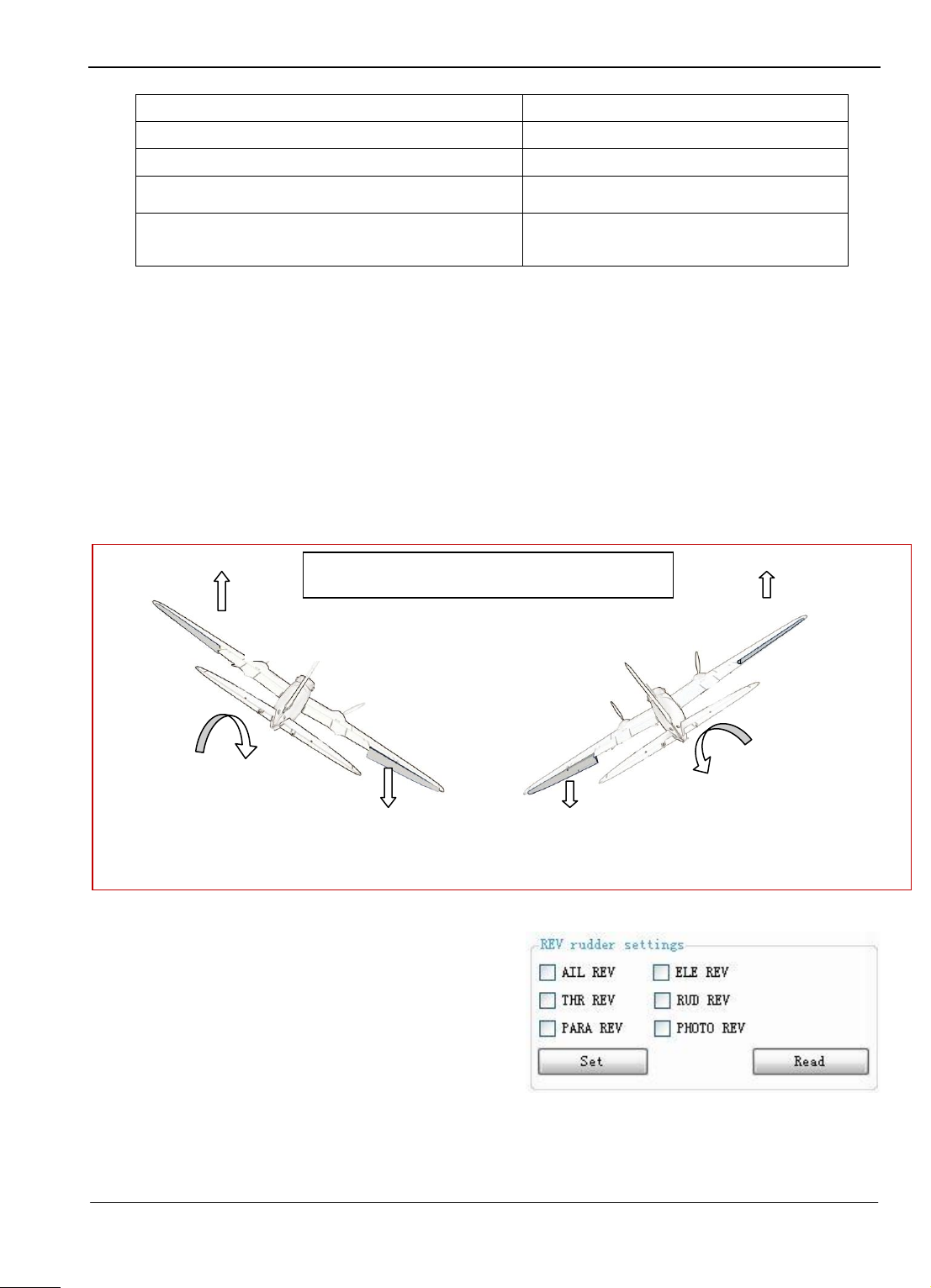
3. REV rudder settings: Set up the servo and throttle control direction.
4. Check Gyro: Gyro testing to see if it works OK.
5. Gyro init: Gyro initialization.
6. Servo neutral: Record servo neutral when in Level flight.
Other settings:
1. Installation Settings: set the install direction of the autopilot (relative to the nose of the
plane). There are four directions, forwards, back, left, right.
2. Time mode: Set the taking photo mode is time interal trigger. E.g. each 5second take one
photo.
3. Distance mode: Set the taking photo mode is distance interal trigger. E.g. each 100m take
one photo.
METER BAR DISPLAY
a) The meter bar provides a graphical aircraft instrument display area.
b) The instrument panel is divided into some sections as shown below:
At the top of the meter bar are the gradienter and course compass, can real-time display
the current attitude and the heading of the plane.
At the bottom of meter bar, there are GPS lock info, voltage, battery power consumed,
Pulse width time of the servo output, target point info, communication data info, and
other data info, etc.
Guilin Feiyu Electronic Technology Co., Ltd http://www.feiyudz.cn service@feiyu-tech.com
Page 33
Page 35

Guilin Feiyu Electronic Technology Co., Ltd
Operations of GCS
1) Connection to autopilot
a) Make sure the hardware connect correctly. Then open the GCS.
b) Click the connection button , chose the serial port. For example, the serial
Com port number here is ―COM1‖, the default Baud rate is ―19200‖.
Guilin Feiyu Electronic Technology Co., Ltd http://www.feiyudz.cn service@feiyu-tech.com
Page 34
Page 36

Guilin Feiyu Electronic Technology Co., Ltd
Click the ―OK‖ button to connect, then click to switch to instrumentation
interface. The changing information is shown on this interface.
2) Air route setting
a) Altitude Initialization
To get accurate altitude recording on the GCS, you need to initialize the altitude record. It is
important to enable 3D flight rendering on the GCS, otherwise it may result in rendering a flight
path outside the map layer.
The GCS can initialize altitude automatically when obtains GPS signal. But if no GPS
position or there is error when auto initialization, you should initialize by yourself.
Click ,The button background will turn green, Click ―tools‖ in the
menu bar and choose ―Altitude Initialization‖, then press the ―Ctrl‖ key, Move the cursor over
the take-off point position in the map and click the left button to confirm. (shown as below)
Guilin Feiyu Electronic Technology Co., Ltd http://www.feiyudz.cn service@feiyu-tech.com
Page 35
Page 37

Guilin Feiyu Electronic Technology Co., Ltd
b) Set the air route
Click ,The button background will turn green, then the waypoint
editing is activated and you can set the route.
The Waypoint setting window will be displayed. Enter the altitude you wish to maintain,
and press Set:
Then click the edit button ,after the background turn green, you can plan the air route
by clicking mouse. Depress the ―Ctrl‖ key, bring the cursor on the map and click where you
want to set the waypoint. The waypoint number and distance flown will be noted.
If you are not satisfied with the planning route, you can reedit it. If you want to change the
position or add the navigation point, simply bring the cursor over the Waypoint you want to edit.
Depress your mouse left button and move to the new waypoint location and let go. The new
location will automatically be updated on the Waypoint list.
You also can edit directly on the ―Edit Waypoint‖ window on the right. Selecting the route
that you want to modify and clicking the right mouse button, modifying the latitude and
longitude of the navigation point by choosing ―Edit‖. (shown as below)
Guilin Feiyu Electronic Technology Co., Ltd http://www.feiyudz.cn service@feiyu-tech.com
Page 36
Page 38

Guilin Feiyu Electronic Technology Co., Ltd
After setting the route, please click ―Upload Waypoints‖ ,to upload the waypoints to
panda autopilot.
You can remove all waypoints by clicking .
You can check the uploaded waypoints in the panda autopilot by pressing the waypoint
download button. Check that the uploaded waypoints are correct: .
c) Home point setting
Reset the home point location when fly in different area. On default, when it has picked up
5 satellite signals it automatically locks the GPS coordinates as the home point.
By using the GCS, you can change this Home location.
Firstly, click Edit waypoints button , than choose ―Edit home point‖
button and make it turn green . Depress the ―Ctrl‖ key and click the target point in the
Google Earth map when ready, then an icon will appear , that means
you have uploaded successfully. At the same time, a hint window will appear .
Note: only by correctly connection can you upload the home points successfully.
Guilin Feiyu Electronic Technology Co., Ltd http://www.feiyudz.cn service@feiyu-tech.com
Page 37
Page 39

Guilin Feiyu Electronic Technology Co., Ltd
d) Save the waypoints
At last, don‘t forget to click this button to save ,otherwise the setting waypoints will be
lost if power down.
Instant Waypoint flying setting
The aircraft can fly to other temporary waypoints, when carry out instant waypoint flying
operation. To enter instant waypoint flying, autopilot should work in stability, path navigation,
RTH or circling mode. When switch to instant waypoint flying mode, you should work in auto
mode (path navigation, RTH or auto circling), because this switch must be via GCS. After ending
instant waypoint flying, the autopilot will carry out those tasks which are interrupted before.
Click the waypoint editing button , when it turn green, meaning you can
edit the waypoint. Click , and make it turn green, it means you have
entered Mouse Click point mode. That is to say, switch the path navigation mode to instant
waypoint flying mode. Choose ―edit target waypoint‖ in .When this
button turn green, depress the ―Ctrl‖ key and click the target point in the map when ready, then
an icon will appear , it means you have uploaded successfully.
The ―Target Point‖ icon will appear , which gives your aircraft the point to fly to.
Instant Waypoint flying cancel: click the button , when it turns green,
meaning you have quitted the instant waypoint flying mode and performed other tasks.
Guilin Feiyu Electronic Technology Co., Ltd http://www.feiyudz.cn service@feiyu-tech.com
Page 38
Page 40

The setup of the Panda can be started once you have finished installing Panda and the
The pulse width of
CH 5
1000-1199μS
1200-1800μs
1801-2000μS
Function
Manual mode
Auto Balance mode
Automatic
Navigation mode
GCS software.
Autopilot Function
Flight Control Mode Description:
1. There are three flight control modes: Manual, Auto Balance and Automatic navigation
mode.
2. You can utilize Channel 5 to determine Flight Control Modes. Use a 3-position switch
on your radio transmitter.
3. Set CH5 to any 3-position switch on your transmitter.
4. Note: Do not set CH5 to Automatic Control Mode when the Autopilot is on.
Manual mode: This is normal RC manual operation. You have full control over the
Auto Balance mode: This provides stabilization only. The pilot still has full control
Automatic navigation mode: In this mode, the autopilot will implement the
Automatic Navigation Mode Description
1. There are two types of Navigation modes:
Path navigation
Instant waypoint setting.
2. The operation of the autopilot is by default set to path navigation.
3. The ground station software is required to change the navigation mode.
4. Path Navigation Mode: The plane will fly according to the pre-set flight path. When it
has reached its final waypoint, it will circle that point.
5. Instant Waypoint Setting Mode: The plane will fly to that instant waypoint
immediately and wait for your next command by performing circling flight hold pattern.
Special Flight Mode Description
There are three types of special flight modes:
Guilin Feiyu Electronic Technology Co., Ltd http://www.feiyudz.cn service@feiyu-tech.com
Guilin Feiyu Electronic Technology Co., Ltd
Panda Debugging instructions
plane. The autopilot is DISABLED.
over the direction, altitude and throttle of the plane.
corresponding automatic control according to the navigation mode which has been set
in the GCS.
Page 39
Page 41

Guilin Feiyu Electronic Technology Co., Ltd
Pulse width of CH6
1000-1199μS
1200-1800μS
1801-2000μS
Function
Return to Home
Idle
Auto Circling
Return to Home (RTH);
Automatic Take-off (Idle);
Auto Circling ;
1. You can set Channel 6 to a 3-position switch to select the Special Flight Modes.
2. The middle position of your three position switch is ―idle mode‖ which means no special
flight modes are active:
3. Return to Home (RTH): No matter what mode your autopilot is in, once RTH mode is
enabled, the plane will initialize RTH (Return to Home). Upon reaching RTH, the
aircraft will initiate a circling holding pattern.(Panda has 50m altitude protection
limited,if the switch point altitude below 50m,Panda will automatic climb to 50m.)
4. Auto Circling: No matter in which mode, once Circling Mode is enabled, the plane will
perform flight holding pattern by circling the current waypoint immediately. The circle
radius is determined by the circle radius you have set. (The default value of the circle
radius is 80 meters when autopilot is enabled.)(Panda has 50m altitude protection
limited,if the switch point altitude below 50m,Panda will automatic climb to 50m.)
5. Automatic Take-off (Idle): In this mode the autopilot is deactivated. You have full
control over your aircraft.
Communication Debugging
1. Turn on your computer, and run the ground station software (GCS).
2. Turn on the adapter board power supply, the adapter plate light will flash slowly.
3. Select the correct communications port from GCS software. Baud Rate is19200.
4. Turn ON your RC Transmitter.
5. Turn ON the autopilot power.
6. If everything is connected correctly, you will see the received telemetry data through the
ground station software, the pressure altitude should be 0 meters (Note: Auto-Initialization
initial boot height is 0 meters).
7. Move your rudder control on the RC transmitter, you will see the rudder output through the
rudder display table. This means the ground station has connected properly with the
autopilot.
Guilin Feiyu Electronic Technology Co., Ltd http://www.feiyudz.cn service@feiyu-tech.com
Page 40
Page 42

Guilin Feiyu Electronic Technology Co., Ltd
8. The FY602 data radio has red and green status lights.
9. FY -602 Red light – Data Radio is ―transmitting‖.
10. FY-602 Green light – Data Radio is ―receiving‖.
11. If you find that transmission of the data radio causes the rudder to ―twitch‖ from interference,
please move the Data Radio transmitter away from the rudder or other effected servos.
Servo Control Direction and Debugging
ATTENTION! It is recommended that you remove your prop or disable your motor while
performing these setup procedures!
1. The Panda module has its own mixing function. Therefore the RC transmitter can be
programmed for a ―normal‖ layout aircraft.
2. Please choose the correct mixing mode in
―Mix control‖ to change the layout of the
aircraft. Following is a table describing the
possible layouts:
Guilin Feiyu Electronic Technology Co., Ltd http://www.feiyudz.cn service@feiyu-tech.com
Page 41
Page 43
Guilin Feiyu Electronic Technology Co., Ltd
Layout
Options
Normal layout plane
Normal& No AIL/Turn via AIL
Delta-winged plane with rudder
Elevons/ Turn via AIL
Delta-winged plane without rudder
Normal& No AIL/Turn via AIL& RUD
Plane without aileron but with elevator and rudder
Elevons/ Turn via AIL& RUD
Left wing aileron automatically
moves upwards.
Roll right
Right wing aileron automatically
moves downwards
Right wing automatically moves upwards
Roll left
Left wing aileron automatically
Pander IN AUTO BALANCE MODE
PRE-FLIGHT CHECK:
3. The following procedure explains how to correct servo control direction upon Panda
activation.
4. Control direction Check.
Switch to the "Auto Balance Mode" mode, check the control direction as explained below.
Aileron Check
1. Holding the plane in your hands roll the plane to the right. The ailerons should give a
signal to counter this roll direction as shown below.
2. If the ailerons move correctly, then you have the correct ―AIL REV‖ setting.
3. If the ailerons do not follow the correct
movement, please set ―AIL REV‖ in the
―REV rudder settings‖ box. You should
now see the correct servo movement after
‗checking‘ reverse.
Elevator check:
1. Holding the plane in your hands tilt the nose up and down. The elevator should give a
signal to counter this tilting motion as shown below:
Guilin Feiyu Electronic Technology Co., Ltd http://www.feiyudz.cn service@feiyu-tech.com
Page 42
Page 44

Guilin Feiyu Electronic Technology Co., Ltd
Rotate right
Rudder moves to the left
Rotate left
Rudder moves to the right
Pander IN AUTO BALANCE MODE
Nose UP
Elevator moves down
Elevator moves up
Nose DOWN
Pander IN AUTO BALANCE MODE
2. If the the elevator does not follow the correct movement, please set ―ELE REV‖ in the
―REV rudder settings‖ box. You should
now see the correct servo movement after
‗checking‘ the box.
Rudder Check:
1. Holding the plane in your hands ―yaw the plane‖ from left to right. The rudder should
give a signal to counter the yaw motion as shown bleow:
2. If the rudder does not follow the correct movement, please set ―RUD REV‖ in the ―REV
rudder settings‖ box. You should now see the correct servo movement after ‗checking‘
the box.
Guilin Feiyu Electronic Technology Co., Ltd http://www.feiyudz.cn service@feiyu-tech.com
Page 43
Page 45

Guilin Feiyu Electronic Technology Co., Ltd
Value set
Turning angle
30
50(default)
70
60° Corresponding angle
18°
30°
42°
Throttle Detection:
1. Warning: It is recommended that you remove your prop or disable your motor while
performing these setup procedure.
2. Pleases refer to the throttle output at the servo display as shown to the right.
3. With your throttle at the lowest setting the number should read 1000. As your throttle up
this number should get larger.
4. If instead the number reads 2000 and gets smaller as you increase the throttle then check
the ―THR REV‖ in the ―REV rudder settings‖ box:
Flight Parameter Setting
The following will explains the function of each flight
parameter setting:
Turn Control
1. Attitude Control: indicates the rate coefficient of
turning angle control.
The higher the value, the greater the turning angle in
degrees.
This Parameter can be set in range from 0-99 degrees.
The maximum attitude angle during the turning
procedure is 45 deg. The Matrix below shows the
relation between Parameter value and angle of the plane
during a turning procedure, with total heading changed
bigger than 60 degrees.
2. Attitude integ: Indicates the (side) angle correction between the designated Flight path
and the plane‘s current position. The higher the value, the faster the system will react to
match the actual flight path and the planned (designated) flight path. This Parameter will
be activated once the plane enters an area less than 30 meters from the planned flight
route.
Range from 0 to 9, default value is 5.
3. Hdg damping: This is to counter the heading change by controlling the gain for angle
control. The higher the value, the greater the angle movement. Range from 0-99. Default
value: 50.
Guilin Feiyu Electronic Technology Co., Ltd http://www.feiyudz.cn service@feiyu-tech.com
Page 44
Page 46

Altitude control
Value
set
Attitude up
30
50(default)
70
10 m
6°
10°
14°
1. Pitch control: The higher the value, the higher the pitch up or down of the aircraft
nose. Maximum pitch up setting is + 20 degrees.
Maximum pitch down setting: - 20 degrees.
Range is 0 to 99. Default value: 50.
The following table shows Pitch angle control when the plane reaches 10 meter altitude:
2. Alt Ofs integ: Also known as Attitude Deviation Integration. This setting controls the
gain to integrate the aircraft current altitude to the target altitude. The higher the value,
the greater the speed to match current and target altitude via pitch control.
Value Range: 0 to99, Default value: 10
3. Altitude damping: Pitch control gain to counter aircraft altitude change. The higher the
value, the greater the pitch action.
Value Range: 0 to 99. Default value: 50.
Throttle control
1. Spd control: This setting controls the aircraft speed in reference to the GPS speed
change. The higher the value, the greater the throttle control gain.
Value Range: 0 to 99. Default value: 50.
2. Spd damping: This setting controls the throttle control gain to counter changes in
airspeed.
The higher the value, the greater the control will gain.
Value Range: 0 to 99. Default value: 50.
Heading stabilization
1. Side Offset Damping:
Adjust gain to control the change in Side Offset damping.
The bigger the value, the bigger the control gain.
Range: 0-9. Default value: 5
2. Rud Turn Control:
When Selecting ―Normal&No AIL/Turn via AIL&RUD‖ or ―Elevons/ Turn via
AIL&RUD‖ in the Mix Control mode manual, the Parameter will be effected.
In these Two control mode, the turning of the plane is complete via both the Aileron and
Rudder.
The ‗Rud Turn Control‘ adjusts the gain of the rudder during automated aircraft turning.
This gain is linearly proportional. i,e, the value should be adjusted according to the Rudder
Guilin Feiyu Electronic Technology Co., Ltd http://www.feiyudz.cn service@feiyu-tech.com
Guilin Feiyu Electronic Technology Co., Ltd
Page 45
Page 47

Guilin Feiyu Electronic Technology Co., Ltd
sensitivity. If your Rudder control sensitivity is high this parameter value should be
reduced, and vice versa.
For all other mix-control modes, the turning is complete via aileron only. Therefore this
‗Rud Turn Control‘ parameter has no effect on the aircraft.
Range :0-99.Default value:60.
3. Rud stab: Control gain to counter the rotation of Z Axis (perpendicular to the body of
the plane).The higher the value, the greater the control gain would be.
Range: 0-99. Default value: 20.
Stability Control
1. Pitch Stability: The amendment control gain given by the change of the flight pitch
angle .The higher of the setting, the greater of the control gain. Setting Range: 0-99.
Default value: 40.
2. Roll Stability: The amendment control gain given by the change of the flight roll
angle .The higher of the setting, the greater of the control gain. Setting Range: 0-99.
Default value: 40.
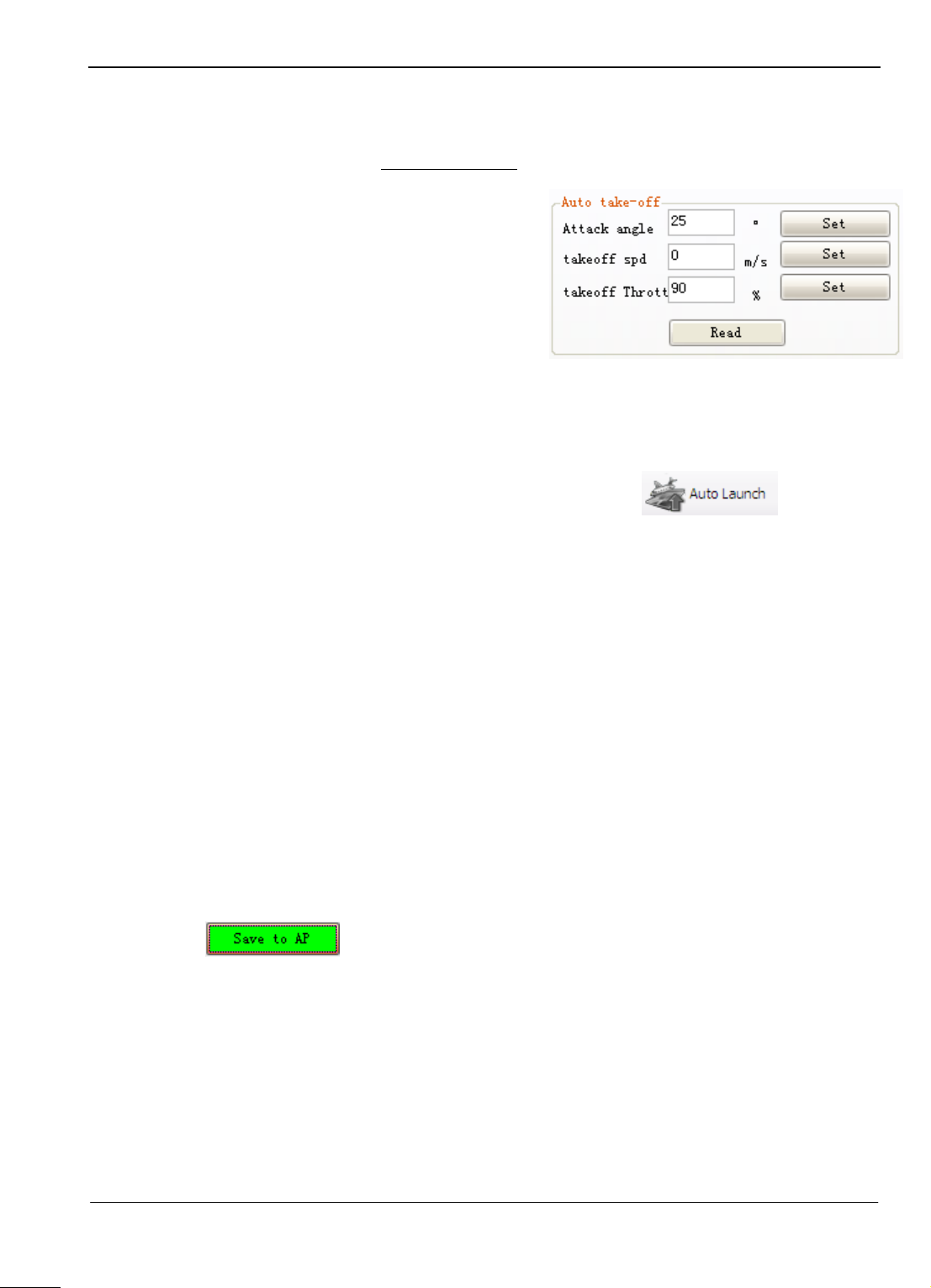
Auto take-off
1. Attack angle: Use this to adjust the Auto take-off pitch setting.
Setting Value Range: 0 to 40 Degrees
2. Take-off Spd: Ground speed setting during
take-off.
Setting Range: 0 to 99 meters per second
Vibration Detection and Adjustment
1. It is critical that the installation of the autopilot meets the vibration damping
requirements.
2. If the installation does not meet the requirements, it will affect the accuracy of the
attitude stabilization greatly.
3. Excessive vibration can cause unpredictable flight characteristics.
Vibration Damping Test Procedure:
1. Connect the power to the system and switch ON the plane.
2. Move the Control Mode switch to Auto Balance Mode or
manual mode.
3. Observe the attitude of the autopilot screen and ensure that
the attitude shown is correct.
4. Slowly activate throttle and spin the motor / propeller. Do not take off!
5. Increase throttle and hold for 20 seconds at different increments.
Guilin Feiyu Electronic Technology Co., Ltd http://www.feiyudz.cn service@feiyu-tech.com
Page 46
Page 48

Guilin Feiyu Electronic Technology Co., Ltd
6. Ensure that the pitch and roll indicators are moving properly and do not deviate.
7. During this throttle increment tests, observe your GCS Screen (above).
8. If the ―Attitude error" sign is activated as shown above, that means the system is
experiencing excessive vibration and the autopilot cannot function properly.
9. Attitude error corresponds to 1000 attitude errors during the test process.
10. Check your installation. Provide additional vibration damping if necessary and restart the
test from the beginning.
The Functions Describe
Auto Photo: the button will turn green when turn on. Autopilot takes photos automatically
according to the setting distance or time interval.
Photo: it will take a picture when click the button. Photo interfaces are controlled by I/O level,
you can select high or low level by setting photo reverse. I/O level can be used to drive the relay,
or control the camera which supports level control directly.
Repeat Path: if setting the navigation path, the plane will not entrance circling mode, while
repeat flies according the setting waypoint. But if you carry out the repeat path after entrancing
circling mode, the plane will not enter repeat flies mode, so you have to switch to auto
navigation mode, then cut in airline operation. Only by this can you carry out this function.
Parachute: click the button to open the umbrella.
Parameter setting
Target Speed: Set the flight cruising speed.
Target Height: Set the current altitude when fixed high flight. You can change the altitude of
fixed high flight when real time set the value.
Circle Radius: Set the circling radius.
Photo Interval: Set the photo interval of auto photo time or distance.
Throttle Hold: Set the throttle control neutral value. This value will be got automatically when
enter automatic mode. You do not need to set.
Photo Taking: Set the time interval from press the camera shutter to make photographs.
Note : if it is the oil machine, you have to check the working stability of motor. Make sure that
the engine not shut down when fast control throttle servo. Here you should set the throttle hold
value.
Guilin Feiyu Electronic Technology Co., Ltd http://www.feiyudz.cn service@feiyu-tech.com
Page 47
Page 49

Guilin Feiyu Electronic Technology Co., Ltd
Flight Path Setting
1. After the autopilot has attained a lock on the home position, a little red plane will show
up on the map at your current position.
2. Set the current location as return point if you wish.
3. To familiarize yourself with flight path setting, try a very simple autopilot flight plan
first.
4. In this example, set a ―Box‖ pattern (above). Set the right height, such as, 200 meters.
5. Ensure that the first tests are done well within visual sight of the plane.
6. When you are more confident with the system is working properly, you can setup a more
complicated flight path.
7. Don‘t forget to click the button to save the path, otherwise the setting waypoints will be
lost if power down.
8. UPLD ROU – After setting the aircraft flight path, save the flight route to the RAM of
the Autopilot by clicking . This flight path will be lost when the autopilot is
powered off.
If you wish to save the flight path for a repeat flight, you can click .
This will save route even after you power OFF the autopilot.
Note that you can store only one route in the autopilot RAM at a time. When you save a
new flight route using ―Save to AP‖, the previous path will be replaced.
The Debugging of after Take- Off
1. This debugging procedure is carried out while the plane is in the air.
2. To carry out this procedure, your plane should be set up well enough to fly straight
without constant correction when in manual mode.
3. Always check the Servo Autopilot Control carefully. For more details, please refer to
Servo Direction Setting.
4. Switch to ―Stabilization Control‖ check to see if there is any unusual movement of the
control and that the auto-balance is functioning
properly.
5. Try rolling and ascending the plane, then let go
of the sticks. Ensure the plane recovers by
itself in both pitch and roll. If it doesn‘t, adjust
the ―pitching stability‖ and ―rolling stability‖ on the stability control and try again until
you feel that the auto balance function is working perfectly.
6. Pitch & Roll Stability: If the plane is pointed down and the sticks are released, and you
observe the plane returning to level too slowly, you need to increase the pitch stability
control. Alternately, if the plane pitches up quickly resulting in and up-down oscillation,
Guilin Feiyu Electronic Technology Co., Ltd http://www.feiyudz.cn service@feiyu-tech.com
Page 48
Page 50

Guilin Feiyu Electronic Technology Co., Ltd
A
B
C
C
A
B
Increase Roll angle control.
C
A
B
Decrease Roll angle control.
then you need to decrease the pitching stability control. The same is true for the roll, if
the plane returns to level flight too slowly then increase the roll stability control. If the
plane rocks back and forth then you need to decrease the roll stability control.
7. After you have finished adjusting in the Auto Balance Mode, adjust the remote control
trims to fly level without input from you.
8. If the Neutral position in this Manual Mode (flight stabilization de-activated) is different
from Auto-balance Mode, then please adjust the angle of installation for the AHRS
Module on the aircraft, so that the two are the same.
9. Alternately, you may use your transmitter trims to level the plane in Auto Balance Mode.
While flying in a straight line and having no input through
the transmitter sticks, click ―servo neutral”. This saves the
trim settings in Auto Balance Mode.
10. Note: If the plane attitude is level and straight while in the
Auto balance Mode, the Deviation of Neutral position between Manual Mode (Stabilizer
Off) and the Auto-Balance Mode won‘t affect the GCS Auto Navigation.
Next test is " Navigation Mode". Test this mode only after you have reached a safe flying
altitude. In this mode, observe the auto navigation flying condition from the ground
station software, and adjust the automatic navigation parameters such as:
Turning Control Adjustment
Route Stability Adjustment
Throttle Control Adjustment and etc.
Turning control Adjustment. For Example:
From Point A to Point B and then to Point C.
Guilin Feiyu Electronic Technology Co., Ltd http://www.feiyudz.cn service@feiyu-tech.com
Page 49
Page 51

Guilin Feiyu Electronic Technology Co., Ltd
B
ABABA B
A
Increase ―Side Offset damping‖ if plane fly like a ―Big S‖ pattern.
Decrease ―Side Offset damping‖ if plane fly in a ―Tight S‖ pattern.
Increase ―Roll integrator‖ if the plane roll to one side only.
Reduce the ―Roll integrator‖ if the plane repeatedly and quickly roll on both sides.
C
A
B
Increase Course damping.
If the plane rolled from side to side during turning, reduce Course damping.
Heading Stabilization Adjustment
1. ―Rudder Stability‖ is useful. It‘s used to
improve the course stability during flying .
2. Notice: The plane will not fly in a straight
line if the settings are too high. For an
example, flight path from A to B.
Altitude Control Adjustment
For an example, Altitude from A to B.
Guilin Feiyu Electronic Technology Co., Ltd http://www.feiyudz.cn service@feiyu-tech.com
Page 50
Page 52

Guilin Feiyu Electronic Technology Co., Ltd
B
ABABA
B
ABABA
If the plane climbs too slowly, increase the ―pitch angle control.‖
If the plane climbs too fast, reduce the ―pitch angle control.‖
Increase ―Height damping‖ if your plane flies in this pattern.
Decrease ―Height damping‖ if your plane flies in this pattern.
Increase ―Pitch integrator‖ if the plane flies higher or lower from your fixed altitude
Decrease ―Pitch integrator‖ when your plane flies in this pattern.
Throttle Control Adjustment
Speed control: Sets the gain to maintain the actual
aircraft speed and the target speed. The higher the
gain, the faster the aircraft will react to changes in
actual aircraft speed.
Speed Offset Integral: an accumulation controlled quantity when deviate from target speed.
Speed damping: sets the amount of ‗buffer‘ for throttle change initiation. If there is a change in
flying speed, that change must exceed the damping value before throttle is reduced or increased.
Generally, you can change the above settings during cruise flight.
Warning: We suggest not increase the settings too high, it may cause very unusual flying
behavior and may result in damage of your aircraft due to excessive throttling.
Guilin Feiyu Electronic Technology Co., Ltd http://www.feiyudz.cn service@feiyu-tech.com
Page 51
Page 53
Guilin Feiyu Electronic Technology Co., Ltd
Auto Take Off
1. The auto take-off feature is designed mainly for hand launched planes.
2. Please select a fairly stable plane if auto take-off is to be used.
3. The Auto Take-off should not be attempted unless you have completed setting up Auto
Balance mode and fill in the Navigation
parameters.
4. Critical Parameter Examples:
Set the climb pitching angle for auto
take-off.
Set the climbing Groundspeed for auto
take-off
Mission: Circle over home-point after
auto take-off.
Auto take off procedure
1. After located by the GPS, click ―Auto Launch‖ in the GCS.
2. When the menu button background color turn to green, set Channel 6 switch to the
position of ―Return to home‖
3. Set the throttle level to the position for taking off.
4. Throw out the plane in a level and straight way.
5. You will notice the plane will fly in a straight line first.
6. When the autopilot detects groundspeed has increased at a value needed for climbing, the
plane will climb up to approximately 50m altitude.
7. Upon reaching 50 meter altitude, the auto take off Procedure is over. Control is
automatically transferred back to your RC transmitter.
8. However, the plane will still continue flying autonomously, gradually circling and
increasing height to 100 meters over the home-point. At this height, the aircraft will hold
altitude.
9. Remember that if you had done any adjustments to the Flight Parameters (e.g. Pitch and
Roll stability), remember to click ―Save to AP‖ to store your settings in the Autopilot.
Failure to save these settings before powering off will result in lost of all adjustments
done.
This manual is just a guideline to help you set up your aircraft for autonomous flight.
As each aircraft is unique, you will need to fine tune the settings to suit your aircraft’s
flight characteristics.
---END---
Note: We reserve the right to change this manual at any time! And the newest edition will be
shown on our website www.feiyudz.cn .
Guilin Feiyu Electronic Technology Co., Ltd http://www.feiyudz.cn service@feiyu-tech.com
Page 52
 Loading...