

Page 1
FY-AHRS-1200A Instructions
Attitude and Heading Reference Systems
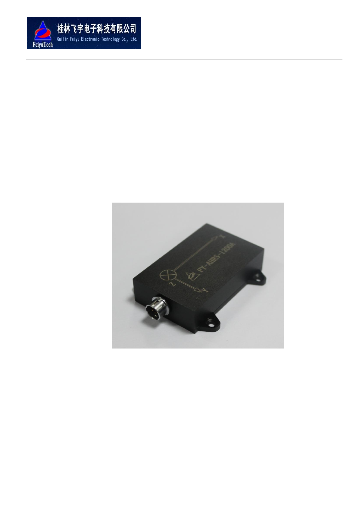
FY-AHRS-1200A
Instructions V1.0
Guilin FeiYu Electronic Technology Co., Ltd
Addr: 4th Floor,Yu Tai Jie Science&technology Building, Information Industry Park,
ChaoYang Road ,Qi Xing District , Guilin 541004, China.
Website: http://www.feiyudz.cn
E-mail: service@feiyu-tech.com
Page 2

GuiLin FeiYu Electronic Technology Co., Ltd
FY-AHRS-1200A is a high-performance strap down inertial navigation system that can measure any
point of orientation of the entire locomotive and vehicle in the 3D space. AHRS could make high-precision
positioning for any stationary or moving objects with angular velocity, even short magnetic interference will
not affect the heading accuracy of the AHRS. The system can be carried out AHRS magnetic field
calibration, to eliminate the hard and soft iron materials motorcycles offset caused by magnetic fields.
Features:
1、Using high-performance all solid-state three-axis accelerometer, three-axis angular rate sensors and
three-axis magnetic field sensor.
2、Three axis 360-degree all-dimensional output of the attitude and heading, attitude and heading data on a
static accuracy of less than 0.2 degrees, the dynamic accuracy of less than 2 degrees.
3、Built-in sensor auto-calibrate, can automatically compensate for the interference of temperature drift,
noise, external magnetic field, etc.
4、Super long time stability and fast dynamic response.
Application:
Ground Transportation
Robots
Aircraft
Video Camera ect.
GuiLin FeiYu Electronic Technology Co., Ltd http://www.feiyudz.cn E-mail: service@feiyu-tech.com
Page 1
Page 3
GuiLin FeiYu Electronic Technology Co., Ltd
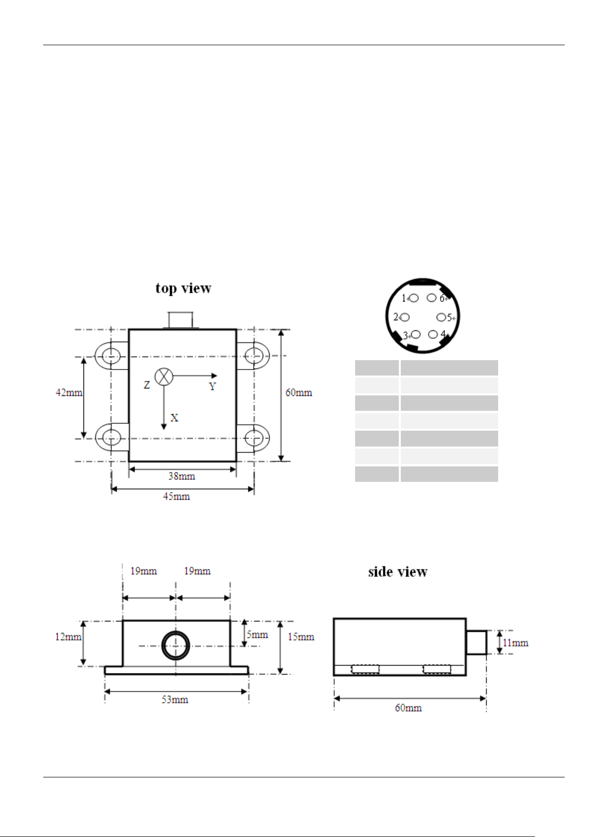
PIN
Signal
1
TX 2 RX 3 Vcc
4
GND
5
Factory used
6
Factory used
The AHRS includes three gyroscopes, three accelerometers and three magnetic field meters.
Real-time measure three axial angular velocity, acceleration, and magnetic field strength.After the
processing by the internal microprocessor, the AHRS outputs drift-free attitude and heading information, the
three-dimensional acceleration, three-dimensional angular velocity, three-dimensional geomagnetic field,
which have been compared and checked-off.
Dimensions and Interface Description:
GuiLin FeiYu Electronic Technology Co., Ltd http://www.feiyudz.cn E-mail: service@feiyu-tech.com
Page 2
Page 4

GuiLin FeiYu Electronic Technology Co., Ltd
Specification
FY-AHRS-1200A
Remark
Performance
Refresh Rate(Hz)
1~100
The default refresh rate is 20Hz
Initialization Time(sec)
3
Heading
Output Range(deg)
0~360
Accuracy(deg)
±1
Compensation and Correction
Resolution(deg)
0.1 Attitude
Roll output range(deg)
±180
Pitch output range(deg)
±90
Static Accuracy(deg)
<0.2
Dynamic accuracy(deg RMS)
<2
Resolution(deg)
0.05
Angular velocity
Roll, Pitch ,Heading(deg/sec)
<1200
Optional range of different
Resolution(deg/sec)
<0.05
Bandwidth(Hz)
100
Linear Acceleration
X, Y, Z axis measuring range(g)
±3 Deviation(mg RMS)
0.3 Bandwidth(Hz)
40 Magnetic field
X, Y, Z axis measuring range(gauss)
±1.5
Output range
-2048~2047
0.769 MG/LSB
Bandwidth(Hz)
20
Environmental Indicators
Working temperature(℃)
-40~+70
Electrical indicators
Input voltage(V)
3.3V~6V
Recommended 5V
Input voltage(mA)
<80
Digital Output
TTL or RS232(Optional)
Baud rate of output
4800~115200
The default baud rate is 19200
Physical index
Size(mm)
60×3 8×15
Length ×width× height
GuiLin FeiYu Electronic Technology Co., Ltd http://www.feiyudz.cn E-mail: service@feiyu-tech.com
Page 3
Page 5

GuiLin FeiYu Electronic Technology Co., Ltd
Weight(g)
50
1、Hardware Installation
FY-AHRS-1200A should be installed on a stable platform; the installation of the surface should be
parallel with the ground as far as possible when still placed on the platform, and keep it away from the
magnetic field effects as far as possible. Magnetic objects must avoid being included. For example: car
engines, electric motors, audio speakers, steel, iron and steel nuts or bolts. We recommend using copper,
plastic or aluminum as the FY-AHRS-1200A installation and packaging materials. Because it equipped with
a gyro and acceleration sensor, so we must fix it on the platform cautiously.
When install FY-AHRS-1200A, make ensure that the "forward" on the shell (it means the positive
X-axis) keep the same direction with the platform move forward straight. This is very important. Once the
installation is finished, you’d better make ensure that no more change in use.
Since magnetic interference may exist in the surroundings, for realize the correction of course, we
advised that please run the magnetic field compensate program of the FY-AHRS-1200A after each time the
environment changed .We must select the install position carefully when install the FY-AHRS-1200A.The
selected position should expose the electronic component fully to the Earth's magnetic field, while keep it
relatively isolated from the magnetic field effects and interference.
FY-AHRS-1200A includes gyroscopes and accelerometers, in order to initialize the sensors, you should
keep it horizontal and static for about 3 to 5 seconds when Power-on .If you power-on it during movement,
its may caused the attitude data accuracy decline.
If the external environment changed so much, when boot and maintain the stationary state, the
gyroscope angular rate is greater than 1 ° per second, please perform "configuration" - "" gyro to initialize ".
2、 Power and Signal Connections
FY-AHRS-1200A connects to the user equipment through standard TTL serial protocol, so if you are
using a notebook computer, please prepare a USB-serial converter. FY-AHRS-1200A factory default serial
port baud rate is 19200, the output data refresh rate is 20Hz.
Recommended operating voltage 5V DC power input.The voltage input range is 3.3V ~ 6V,if the
supply voltage is out of the range, the AHRS will be damaged or caused performance reduction.
3、Demo Software Installation and Use
The demo software program's document of FY-AHRS-1200A is AHRS test software.exe, after
complete the installation, the interface is as follows:
GuiLin FeiYu Electronic Technology Co., Ltd http://www.feiyudz.cn E-mail: service@feiyu-tech.com
Page 4
Page 6

GuiLin FeiYu Electronic Technology Co., Ltd
Select the serial port used to connect in the "Port" field, such as: "COM1"; in the "Rate" field select the
baud rate as "19200"; FY-AHRS-1200A connected to the default wave special rate of 19200, a start-byte, 8
data bytes, a Stop byte, no parity, either hardware or software no "handshake." Baud rate can be changed by
command.
Click "Open Serial Port" button, if the FY-AHRS-1200A has been powered on and in working status,
you will see the attitude, angular rate and other parameters displayed on the left window. After click
"Graphic Demo" button, the 3D graphics demo window will be pop-up.
The three-dimensional rectangular in the demo program will change its attitude accordingly thought the change
attitude of the FY-AHRS-1200A.
GuiLin FeiYu Electronic Technology Co., Ltd http://www.feiyudz.cn E-mail: service@feiyu-tech.com
Page 5
Page 7

GuiLin FeiYu Electronic Technology Co., Ltd
Select the menu "Show" - “electronic compass display ", you can switch to two dimensions compass
view, its will indicating the real time course.
At the main interface of AHRS testing software, you can configure the output serial baud rate, the
output data refresh rate, the output data content, etc, and you also can set the baseline calibration and the
magnetic field calibration of the sensors inside the FY-AHRS-1200A.
GuiLin FeiYu Electronic Technology Co., Ltd http://www.feiyudz.cn E-mail: service@feiyu-tech.com
Page 6
Page 8

GuiLin FeiYu Electronic Technology Co., Ltd
4、Magnetic field calibration
FY-AHRS-1200A will be started magnetic compensation calibration procedures once the installation
finished. The magnetic field compensation process in the module's firmware determines the magnetic field
calibration impact of the installation of platform, so even if the FY-AHRS-1200A is installed on the steel
device (for example, a vehicle), its still can provide accurate readings. FY-AHRS-1200A has the
compensation effect only in a limited interference range. Range value of magnetometer is between minus
100 and plus 100 m-Teslas which is approximately twice the magnetic force in middle latitude northern
hemisphere,. If the disturbance value of the magnetic field more than plus or minus 50 m-Teslas, the
magnetometer could reach saturation and block compensation.
Magnetic compensation function is semi-automatic. Once started, FY-AHRS-1200A will collect data
automatically from every position of the circumference. After complete this work, the module will calculate
the correction factor to compensate for the near magnetic field abnormalities, and to store the corrected
value in the permanent memory. After the compensation process, the corrected value will be merged into the
subsequent azimuth data.
If necessary, the compensation process can be repeated several times. When began to run the test
program, please note: The magnetic objects (such as the nearby mobile phones, structural steel and buried
underground pipelines) may lead to azimuth errors. If the FY-AHRS-1200A is installed in a vehicle, it will
encounter the magnetic field anomaly; this is why there is a magnetic compensation procedure. However,
for some bulky magnetic properties are very likely to distort the earth’s magnetic field, even the process of
magnetic compensation happened in a long distance.
Magnetic declination and bias of installation is the most important parameter values, which can be
entered into the module by the host. Usually, when power-on, the module will automatically set the value of
magnetic declination and bias to 0. This can be changed through software commands, and the value is still
valid after restarted.
Magnetic declination (also known as magnetic variable) is the angle between true north and magnetic
north. Azimuth bias is defined as the level angle deviation between the module's forward axis (X axis) and
the reference axis of installation platforms. Azimuth bias is a constant, which is decided the module
mechanical placement and installation elements. Magnetic declination and Azimuth bias will affect the
accuracy of the Azimuth observation.The module should use these two corrected values, and add it to the
magnetic field course deviation angle correction option.
According to usual practice, both the mark symbol of magnetic declination and azimuth bias used in
the east are belonging to positive sign. For example, if magnetic north is the east of true north, magnetic
declination is positive. For example, the local magnetic declination is -6 °, the install bias is -2 °, and then
the magnetic field course deviation angle correction option should fill in the 8 °.
In the implementation of the "Start calibration of XY-axis magnetic field", you need to place
FY-AHRS-1200A horizontally (the X-Y plane of FY-AHRS-1200A is parallel with the ground level. At the
same time, the right side of Z-axis being faced down with the ground water level vertically), and rotate the
module clockwisely, keep it stable circular movement. If the FY-AHRS-1200A is installed in a vehicle, the
above steps are completed by rotate the vehicles slowly on the horizontal ground.
GuiLin FeiYu Electronic Technology Co., Ltd http://www.feiyudz.cn E-mail: service@feiyu-tech.com
Page 7
Page 9

GuiLin FeiYu Electronic Technology Co., Ltd
The magnetic field calibration process will show the current rotation angle by drawing the circle. You
must clockwise rotate FY-AHRS-1200A continuously until the end of the amendment.
If the drawn circumference is significantly distortion, its may coursed by the overlarge external
magnetic interference or there are problems in the process of rotation, so you must re-calibrate.
By the end of the magnetic field calibration, click "Write FLASH” button, its will write the amend
parameters in the FLASH and keep them permanently. At the same installation platform, if the external
environment is not change too much, one time amendment will be enough.
Note: You must click “Write FLASH” button, if all the configuration parameters has any changes, or
select the menu "Configuration" - "" permanently save the configuration parameters ",its will write
the configuration parameters in the FLASH and keep them permanently, otherwise ,these
configuration parameters will be lost in the next electrified time .
FY-AHRS-1200A Interface Protocol
FY-AHRS-1200A Data output format description (standard RS-232, ASCII character output):
Command head, field1, field 2, field 3, • • • • • •, the field n * checksum field (CRLF)
Between the fields with "," separated, each with a carriage return line feed end of the data.
FY-AHRS-1200A attitude data format
GuiLin FeiYu Electronic Technology Co., Ltd http://www.feiyudz.cn E-mail: service@feiyu-tech.com
Page 8
Page 10

GuiLin FeiYu Electronic Technology Co., Ltd
Command
type
Command
head
Field 1
field 2
field 3
field 4
field 5
field 6
attitude data
$FYZT
Pitch
Roll
heading
X
angular
rate
Y
angular
rate
Z
angular
rate
field 7
field 8
field 9
field 10
field 11
field 12
field 13
Check
X
Acceleration
Y
Acceleratio
n
Z
Acceleratio
n
resultant
acceleration
X
magneti
c field
Y
magneti
c field
Z
magneti
c field
* Check
value
Command
type
Command
head
Command
NO
Parameter
1
Parameter
2
parameter
3
parameter
4
Configure the
output refresh
rate
$Config
6
Refresh rate
settings,
Parameter setting
range
1 — 100
1, 100Hz
2, 50Hz
5, 20Hz
10, 10Hz
100,1Hz
NULL
NULL
NULL
Configure the
output baudrate
$Config
7
Baudrate
settings,
Parameter setting
range
0 — 7
0,4800
1,9600
2,14400
3,19200
NULL
NULL
NULL
FY-AHRS-1200A attitude data output example:
$FYZT,-0.92,-0.60,341.77,-0.15,0.14,0.11,0.02,-0.01,1.00,1.00,447.19,140.02,159.50*F4
Check value calculation method: arithmetic accumulate all data by-byte start from each "$" of the data
symbols (including the $) to the"*" (excluding “*”).
FY-AHRS-1200A Configuration Format Description (standard RS-232, ASCII character input):
Command head, command NO, parameter1, parameter2,……,parameter n (CRLF).
Between the fields with "," separated, with a carriage return line feed end of each data.
GuiLin FeiYu Electronic Technology Co., Ltd http://www.feiyudz.cn E-mail: service@feiyu-tech.com
Page 9
Page 11

GuiLin FeiYu Electronic Technology Co., Ltd
4,38400
5,56000
6,57600
7,115200
Configure
magnetic
declination
$Config
4
Setting of the
magnetic
declination,
Parameter setting
range
-360 — 360
For setting the
magnetic
deviation angle
and installed
heading bias
NULL
NULL
NULL
Open/Close the
FY -AHRS-1200A
serial data
output
$Config
9
Parameter setting
range
0 — 1
0,close
1,open
NULL
NULL
NULL
Command
type
Command
head
Command
NO
Parameter
1
Parameter
2
parameter
3
parameter
4
magnetic field
calibration
$Config
10
The magnetic
field calibration
options
1 — 2
1,Start calibration
XY-axis magnetic
field
2,Reserved.
After send this
command, must
clockwise rotate
FY-AHRS-1200A
horizontally to
complete the
magnetic field
calibration
NULL
NULL
NULL
write the
configuration
information
in the FLASH
$Config
99
Is fixed at 1
Once configured,
send this
command to write
NULL
NULL
NULL
GuiLin FeiYu Electronic Technology Co., Ltd http://www.feiyudz.cn E-mail: service@feiyu-tech.com
Page 10
Page 12

GuiLin FeiYu Electronic Technology Co., Ltd
the configuration
information in the
FLASH
FY-AHRS-1200A attitude configure command example:
$Config,9,1 (CRLF)
Open the FY-AHRS-1200A serial data output
$Config,4,16 (CRLF)
Configure the FY-AHRS-1200A magnetic field deviation angle of 16 degrees.
$Config,99,1(CRLF)
Write the configuration information to the FLASH.
——END——
Note: We reserve the right to change this manual at any time! And the newest edition will be shown
on our website www.feiyudz.cn.
GuiLin FeiYu Electronic Technology Co., Ltd http://www.feiyudz.cn E-mail: service@feiyu-tech.com
Page 11
 Loading...