How it Works
Log In / Sign Up
Buy Points
How it Works
FAQ
Contact Us
Questions and Suggestions
Users
fanuc
Loading...
B
B-63874EN-11
B-63874IT
B-63944EN
B-63944JA
B-63945EN
2
B-63945JA
B-64305EN
B-64603EN-01
B-64644CM-1-06
B-64644CM-2-01
B-64644CM-3-01
B-64647EN-01
B-64654CM-02
B-64692CM/01
3
B-64692EN
B-64693CM
B-64693EN
B-64694CM
B-64695CM
B-64700CM/01
B-65270EN
B-65270JA
B-65280EN
B-65280JA
B-65285E
B-65285EN
B-65285JA
B-65325EN
2
B-65325JA
B-65395EN
B-65395JA
B-82594EN-6
BUILT-IN SPINDLE MOTOR Bi
2
BUILT-IN SPINDLE MOTOR Dis
2
C
C1000
4
C1000iA
2
C2000
4
C4000
4
E
E 0i Mate-E
2
F
FH550SX
FH630SX
3
FOCAS ethernet driver
G
GFK-1046E
GFK-1702
GFK-1703
GFK-1709
GFK-1710
GFK-1711
GFZ-62072E-01
GFZ-62073E-2-03
GFZ-62075E-03
GFZ-62564E-02
GFZ-65042E
I
i CELL
Intelligent Robot
IO-A
2
IO - B
IO Link-II
L
Laser C
2
LINEAR MOTOR LiS
2
LR mate 200iD
M
M-1iA/0.5A
2
M-1iA/0.5S
2
M900iA
O
Oi - *d
Oi Mate D
5
OI-PD
P
POSITIONER
3
Q
quaeroCNC
R
R-30IA
3
R-30IA MATE
3
R30iB
2
RJ3iB
S
Series 0i Mate-MC
6
Series 0i Mate-MODEL C
7
Series 0i Mate-TC
6
Series 0i-MC
6
Series 0i-MODEL C
7
Series 0i-PC
2
Series 0i-TC
6
SERVO AMPLIF IER
SERVO AMPLIFIER ai
SERVO AMPLIFIER Beta i series
SERVO AMPLIFIER αi
2
SERVO AMPLIFIER βi
4
SERVO MOTOR Alpha i
SERVO MOTOR Beta i
SERVO MOTOR αi
SPINDLE MOTOR Alpha i
SPINDLE MOTOR Beta i
Super CAP IIf
Super CAP II M
Super CAP II T
Super CAP M
Super CAP T
Symbolic CAP T
SYNCHRONOUS
2
T
TURN MATE i
Loading...
Loading...
Nothing found
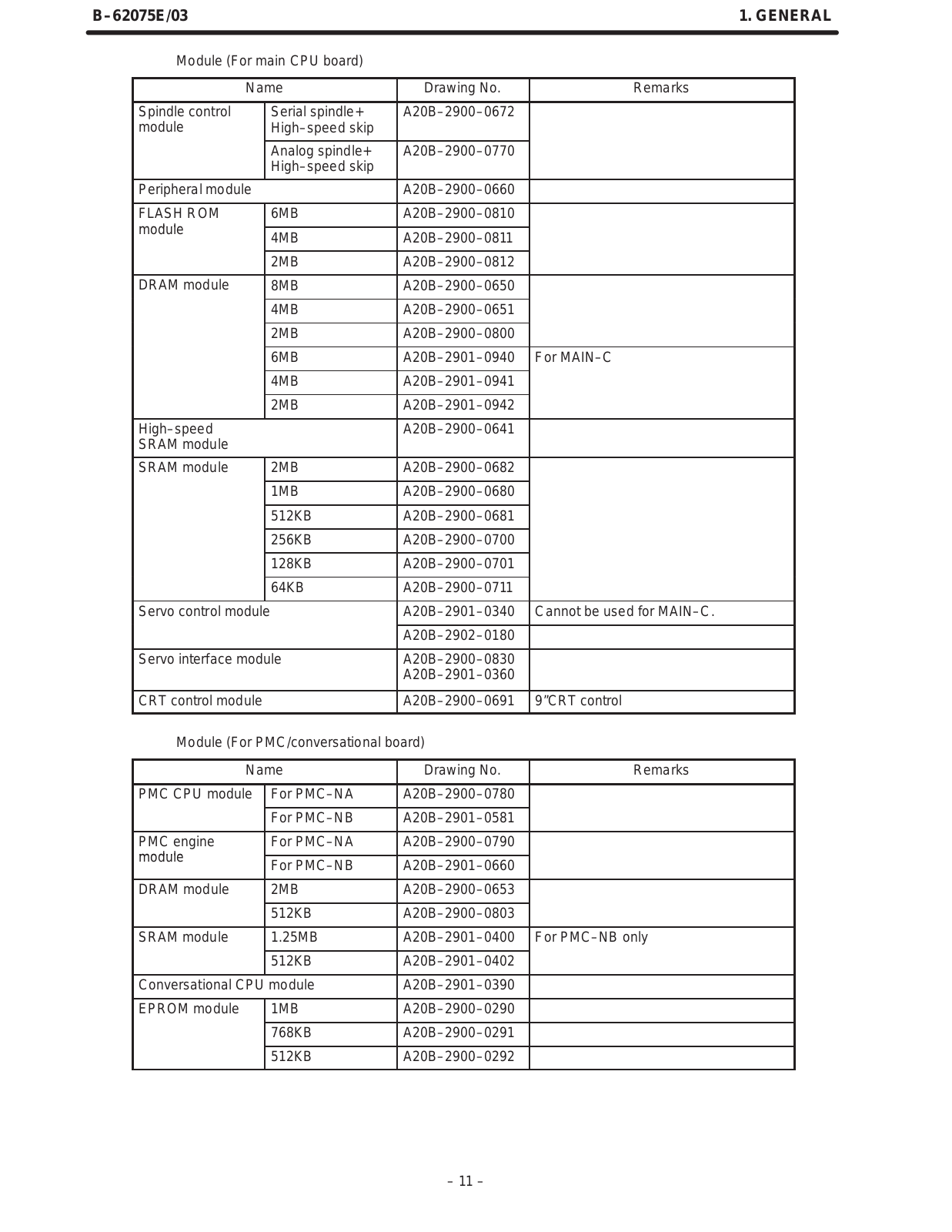
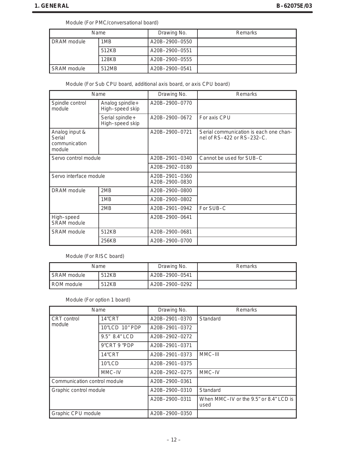
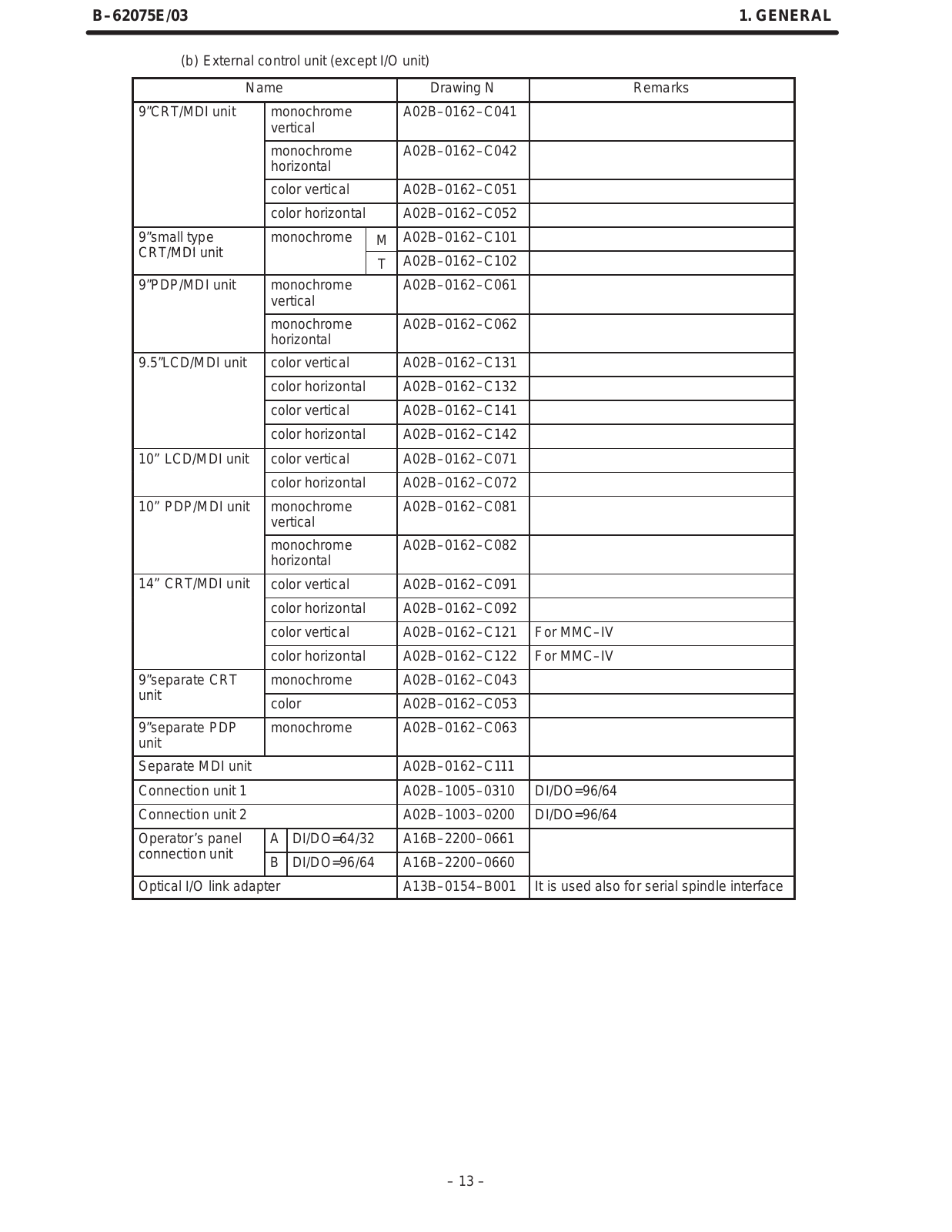
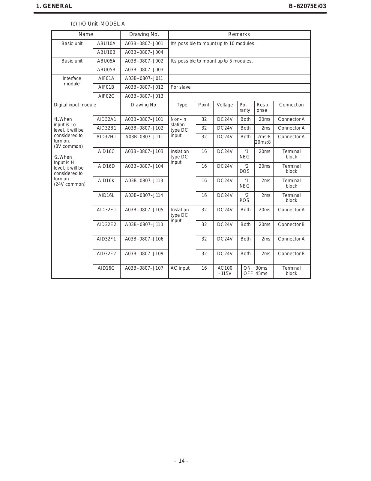
GFZ-62075E-03
Maintenance Manua
243 pgs
956.41 Kb
0
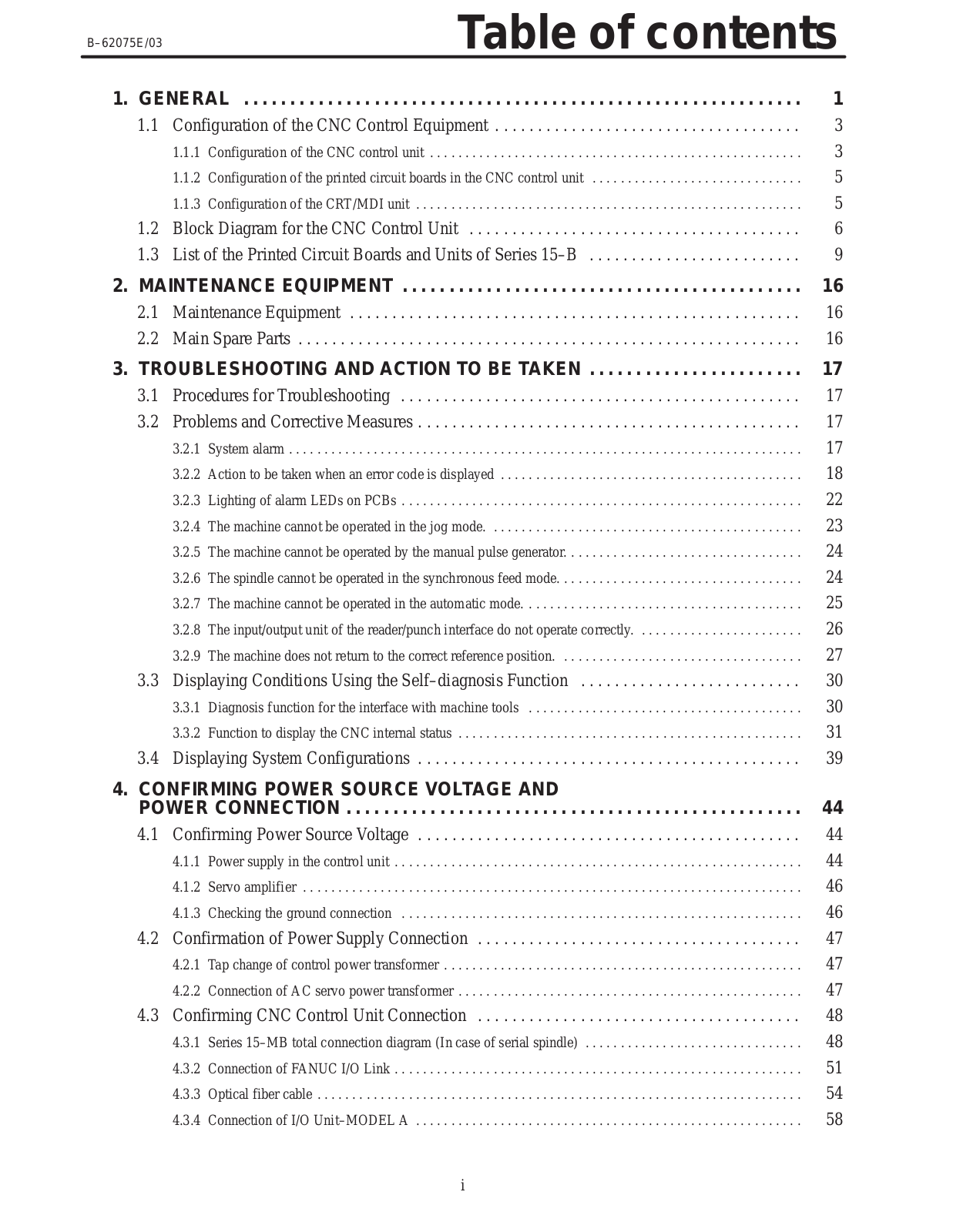
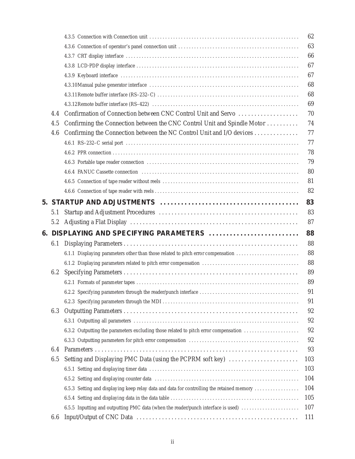
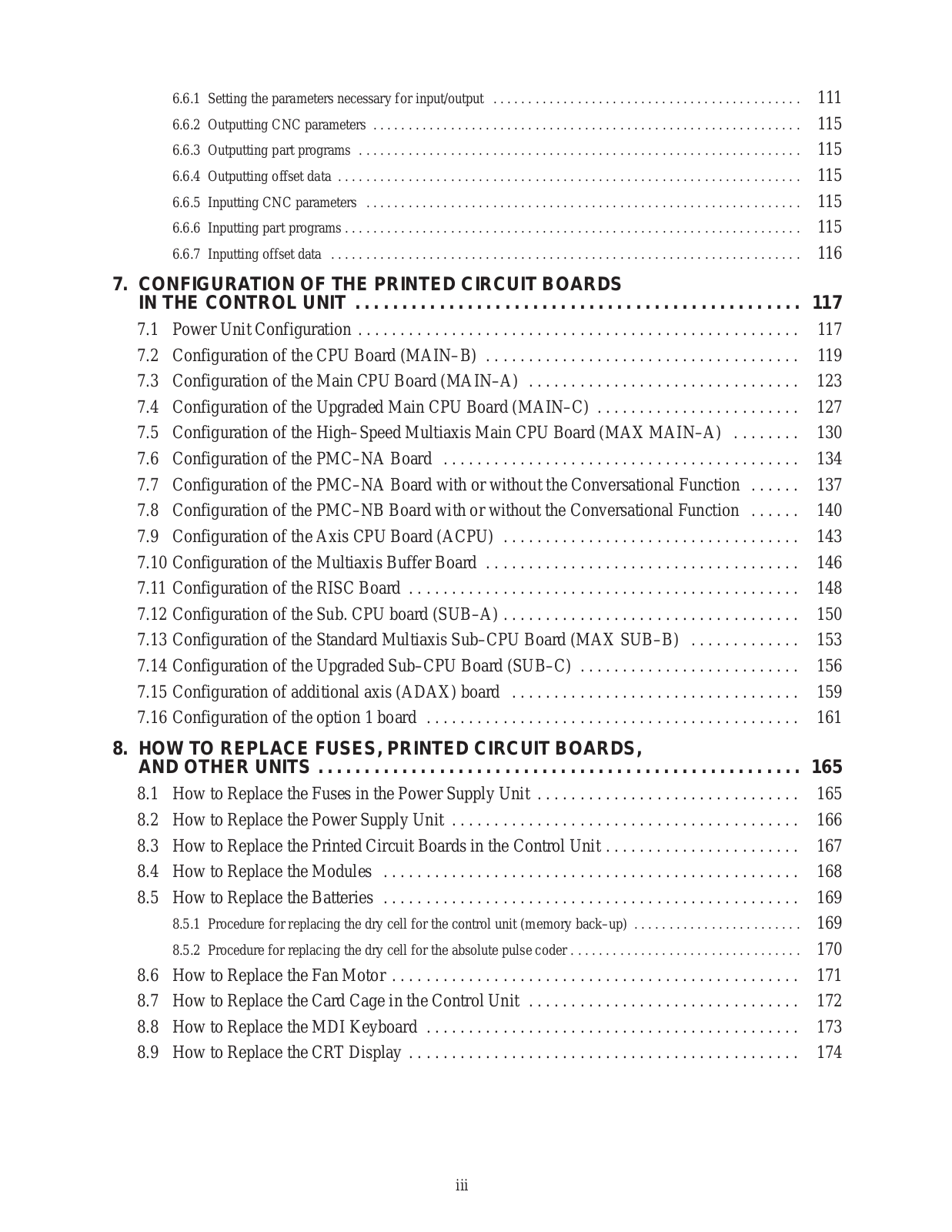
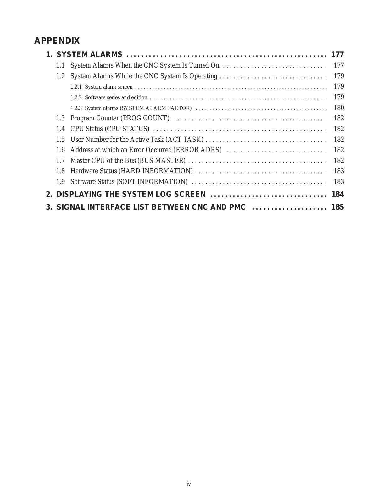
Table of contents
Loading...
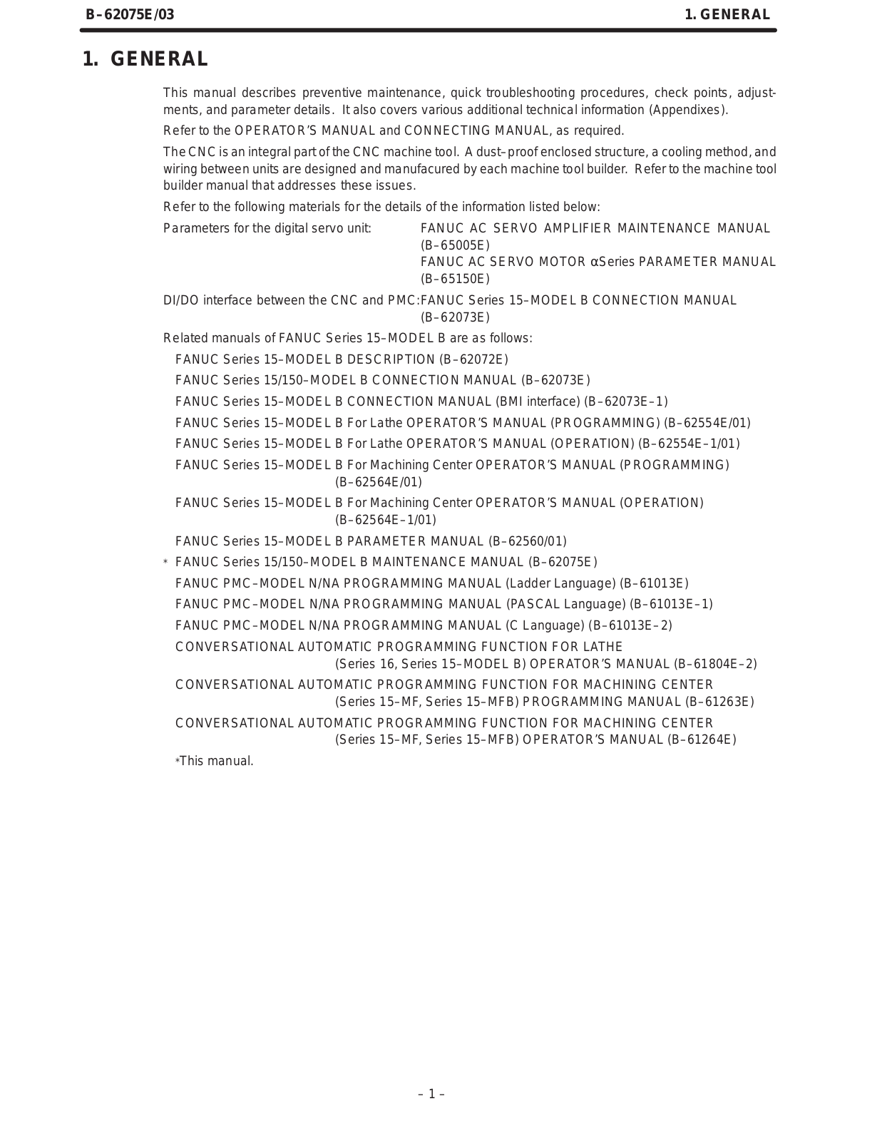
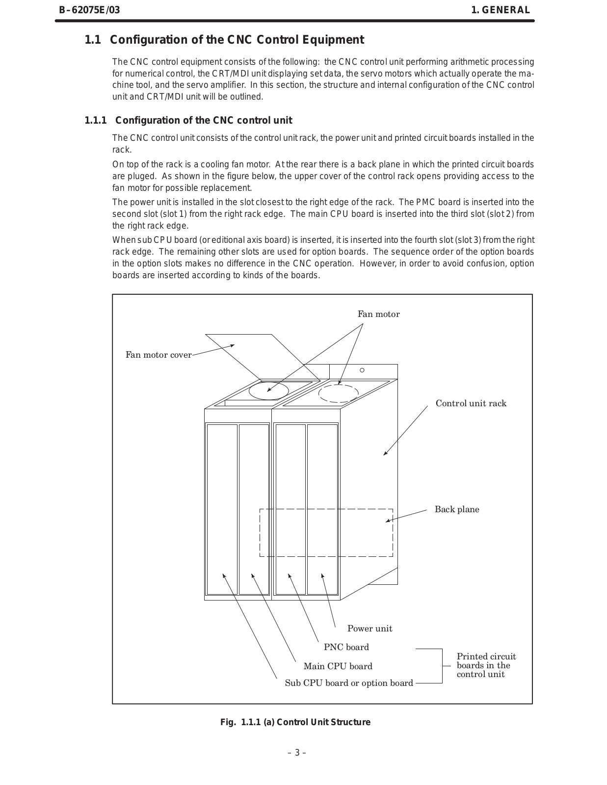
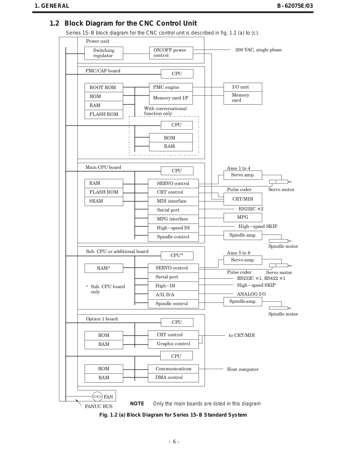
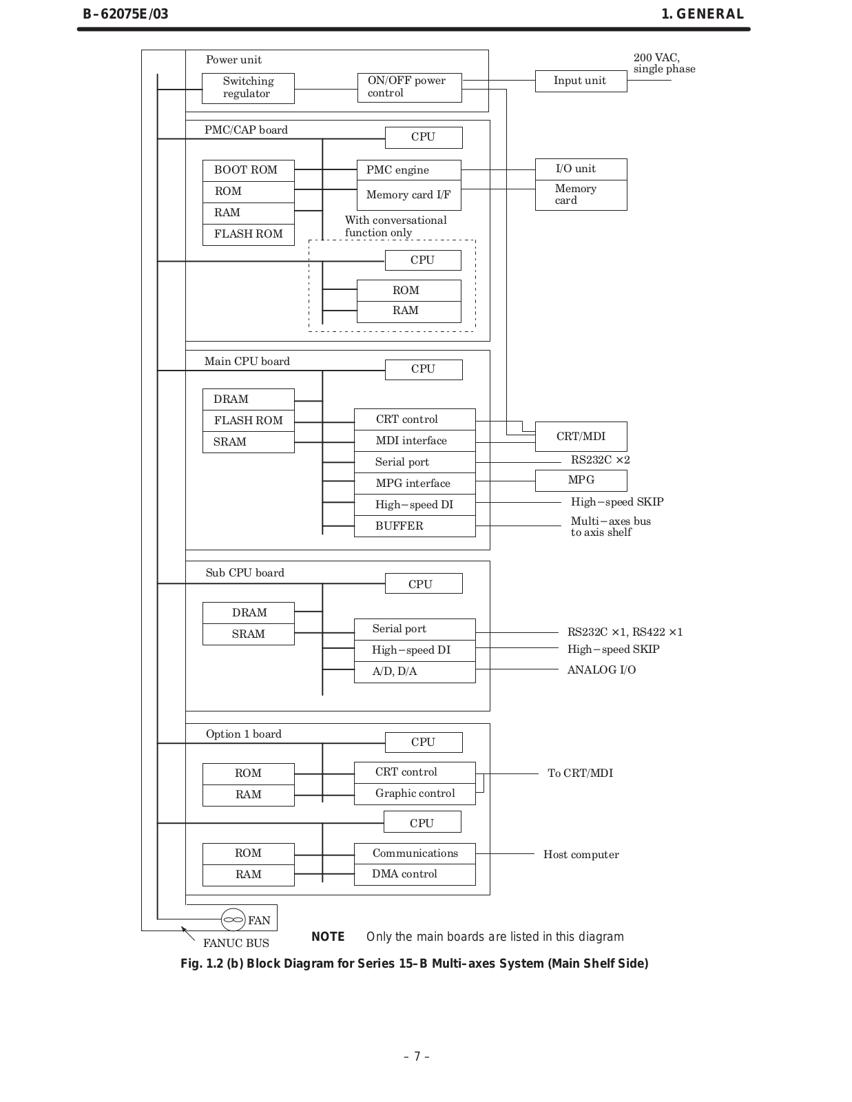
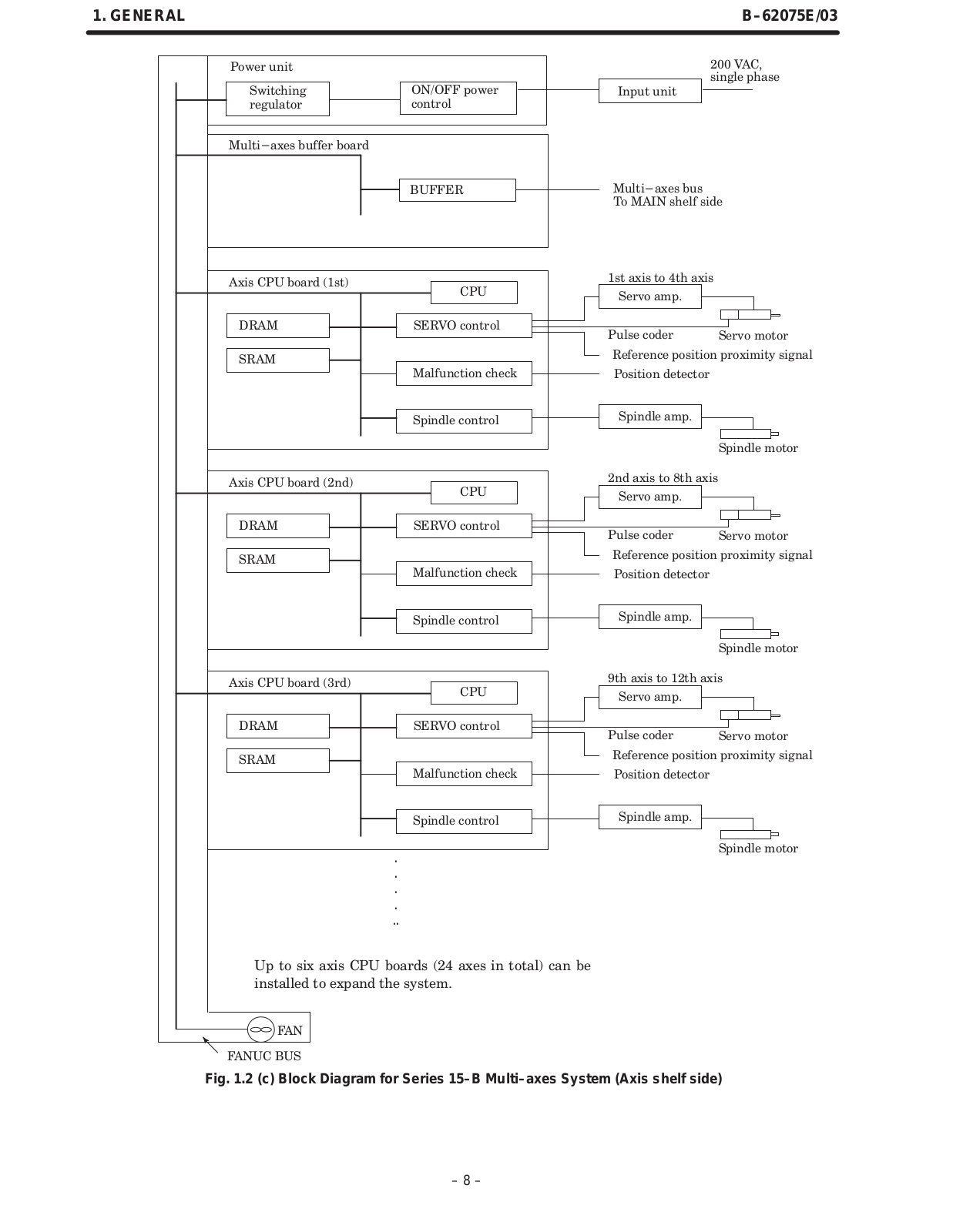
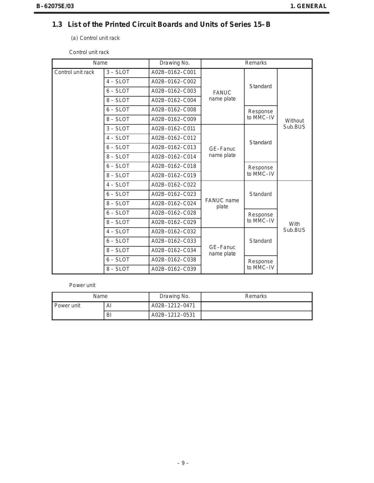
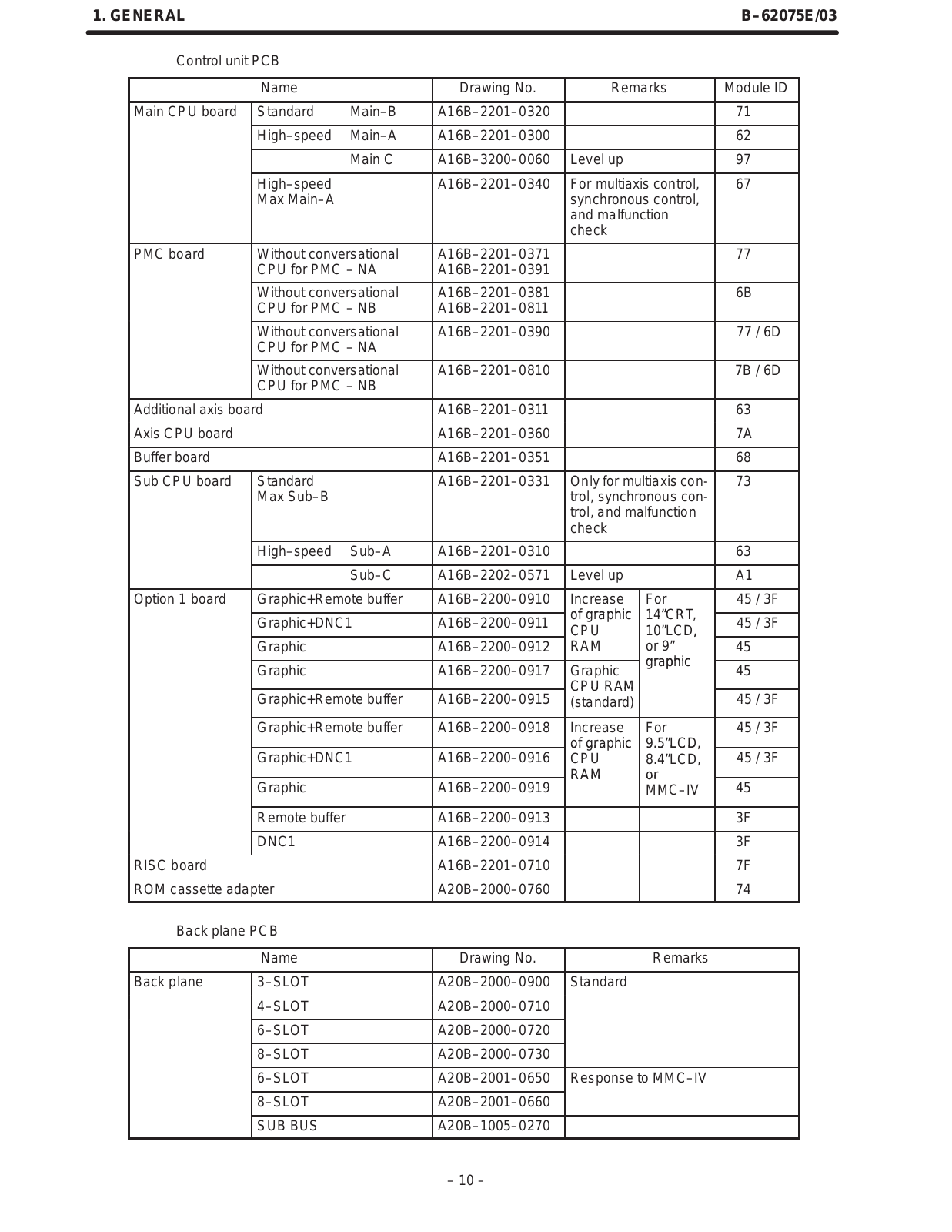
fanuc GFZ-62075E-03 Maintenance Manua
...
fanuc Maintenance Manua
Download
Specifications and Main Features
Frequently Asked Questions
User Manual
Download
Loading...
+
213
hidden pages
Unhide
You need points to download manuals.
1 point = 1 manual.
You can buy points or you can get point for every manual you upload.
Buy points
Upload your manuals
 Loading...