

Page 1
Gibbs and Associates
323 Science Drive
Moorpark, CA 93021
(805) 523-0004
March 1999
SolidSurfacer
USER MANUAL
Page 2

PROPRIETARY NOTICE
This document contains propriety information of Gibbs and Associates and is to be used only
pursuant to and in conjunction with the license granted to you with respect to the accompanying Gibbs
and Associates licensed software. Except as expressly permitted in the license, no part of this document
may be reproduced, transmitted, transcribed, stored in a retrieval system, or translated into any language
or computer language, in any form or by any means, electronic, magnetic, optical, chemical, manual or
otherwise, without the prior written permission from a duly authorized representative of Gibbs and
Associates.
It is strongly advised that you carefully review the license in order that you understand your
rights and obligations related to the licensed software and the accompanying user documentation.
Use of the computer software and the user documentation has been provided pursuant to a
Gibbs and Associates license agreement.
© Copyright 1998 Gibbs and Associates, Inc.
All Rights Reserved
Acknowledgements:
Written by Shannon McConville and Good Wil Gaffga.
Thanks to Bill Gibbs, Tim Alvord, Sean Canterbury, Gary Esser, Charles Haden, Tom Hubina, Kristin
Esser, Al Martins, Israel Klain, Jeff Myers for their input and assistance.
Trademarks:
Windows NT and Windows 95 are trademarks of Microsoft Corporation
Macintosh is a trademark of Apple Computer, Inc.
Printed in the United States of America
◆
SolidSurfacer User Manual #GFK-1709
Page 3

Table of Contents
INTRODUCTION 1
CHAPTER 1
:
INTERFACE 5
Level 2 Interface ...............................................................7
Taskbar ......................................................................7
Right Mouse Click .............................................................7
Body Bag ....................................................................8
History Dialog.................................................................8
Colors .......................................................................9
Slide Bars ....................................................................9
Pointer Markers................................................................9
CHAPTER 2
:
MODELING 11
Introduction to Modeling .......................................................13
Modeling Reference...........................................................20
Modifying Bodies ............................................................62
Modeling Tips and Techniques ..................................................67
CHAPTER 3
:
MODELING EXERCISES 69
Exercise #1: Phone ...........................................................71
Exercise #2: Hot Punch .......................................................85
Exercise #3: Teapot...........................................................91
Exercise #4: Plumbing........................................................113
Exercise #5: Remote Control Casing ............................................125
Exercise #6: Fish belt ........................................................141
CHAPTER 4: DATA EXCHANGE 161
Import .....................................................................163
Parasolids Files, ACIS (.sat) Files, IGES Surface Files
Exercise: Healing ............................................................169
Export .....................................................................183
File Extensions ..............................................................184
CHAPTER 5: MULTI-SURFACE MACHINING 187
Introduction To 3-Axis Machining...............................................189
Machining Palette ...........................................................190
Contouring Process...........................................................190
GFK-1709 T able of Contents
◆
i
Page 4

Roughing Process ...........................................................196
Surfacing Process ...........................................................200
CHAPTER 6: MACHINING EXERCISES 219
Exercise #1: Phone..........................................................221
Exercise #2: Hot Punch ......................................................245
Exercise #3: Plumbing .......................................................253
Exercise #4: 2D Contour .....................................................275
Exercise #5: Remote Control Casing............................................285
APPENDIX 1: GLOSSARY 309
APPENDIX 2: PART PRINTS 315
Part Print #1: Phone .........................................................317
Part Print #2: Hot Punch ......................................................319
Part Print #3: Plumbing.......................................................321
Part Print #4: Plumbing Views .................................................323
Part Print #5: Fish Belt .......................................................325
Part Print #6: Fish Belt Views..................................................327
INDEX 329
◆
SolidSurfacer User Manual GFK-1709
ii
Page 5

Introduction
The SolidSurfacer option allows users to define parts using solid and surface modeling tech-
niques. This manual is composed of two types of sections: reference and tutorial. It is recommended
that the user briefly review the reference material and then move on to the accompanying instructional exercises.
There are three primary methods of using the capabilities of SolidSurfacer to create part models that can be machined. The first method is creating solid models from part blueprints using the
solid modeling functions contained in the system. There are many powerful modeling functions
including adding, subtracting and intersecting solids, automatic chamfering and filleting, and several
methods for generating solid bodies from geometry.
Secondly, the system can directly read solid model formats generated by other CAD packages.
Parasolids and SAT files can be directly opened by the system. SAT files require the purchase of an
additional option. The system does not use an importation filter or any means of translation for these
solid files, but rather, directly reads them.
The final method is through the importation of 3D surface files. The system recognizes and
imports several surface entities. Once a surface file is brought into the system, it can either be made
into a solid, using the Solidify functions, or can be kept as a surface model and machined.
Regardless of the method used to define the part, the final model can be machined using the
3D surfacing capabilities. The standard Roughing and Contouring functions can be applied to solid
bodies and surfaces. There is also a Surfacing function that provides several methods for generating
3-axis toolpaths to efficiently cut complex solid and surface part models.
Users should familiarize themselves with the basics of the system which are outlined in the
Geometry Creation Manual, Mill Module Manual and Advanced Milling Manual before reviewing
this manual. This manual assumes a level of proficiency with geometry creation, coordinate systems
and basic machining.
GFK-1709 Introduction
◆
1
Page 6
CHAPTER 1
:
Interface
This chapter describes interface items that are specific to the system when the SolidSurfacer
option is installed. The Mill Module Manual and Geometry Creation Manual contain descriptions of
standard system interface items.
LEVEL 2 INTERFACE
The system has three different levels of functionality. Each level makes slight changes
to the interface. In order to use the SolidSurfacer capabilities, the user must be working
with the Level 2 interface. The interface level is specified in the Interface Preferences
accessed from the Preferences submenu under the File menu. The Level 2 interface is
characterized by a 14 button Top Level palette and a taskbar.
TASKBAR
The taskbar is located along the top of the drawing window, below the menu bar. The taskbar
contains a series of buttons which affect the drawing and selection of items in the drawing window.
Each of the buttons has two states, depressed (on) or raised (off). The taskbar also contains a
progress bar and message display. The progress messages indicate the function the system is performing and the progress bar gives the status of the function. The Stop button can be depressed to
stop the current function. The current workgroup and coordinate system are displayed next to the
progress bar.
RIGHT MOUSE CLICK
The mouse has two buttons that are used in different manners. The left mouse button
selects/deselects and accesses items: geometry, bodies, text boxes, buttons, etc. Clicking the right
mouse button on certain objects accesses context menus which contain items specific to the selected
objects. Right mouse click on the title bar of certain dialogs and a pull down menu containing items
specific to that dialog will appear. Also, right mouse clicking on a body or sheet accesses a menu
containing such functions as Recreate, History and Properties. The Modeling Chapter contains a section which lists all of the available context menus and the functionality of the items contained in
these menus.
◆
SolidSurfacer User Manual GFK-1709
2
Page 7
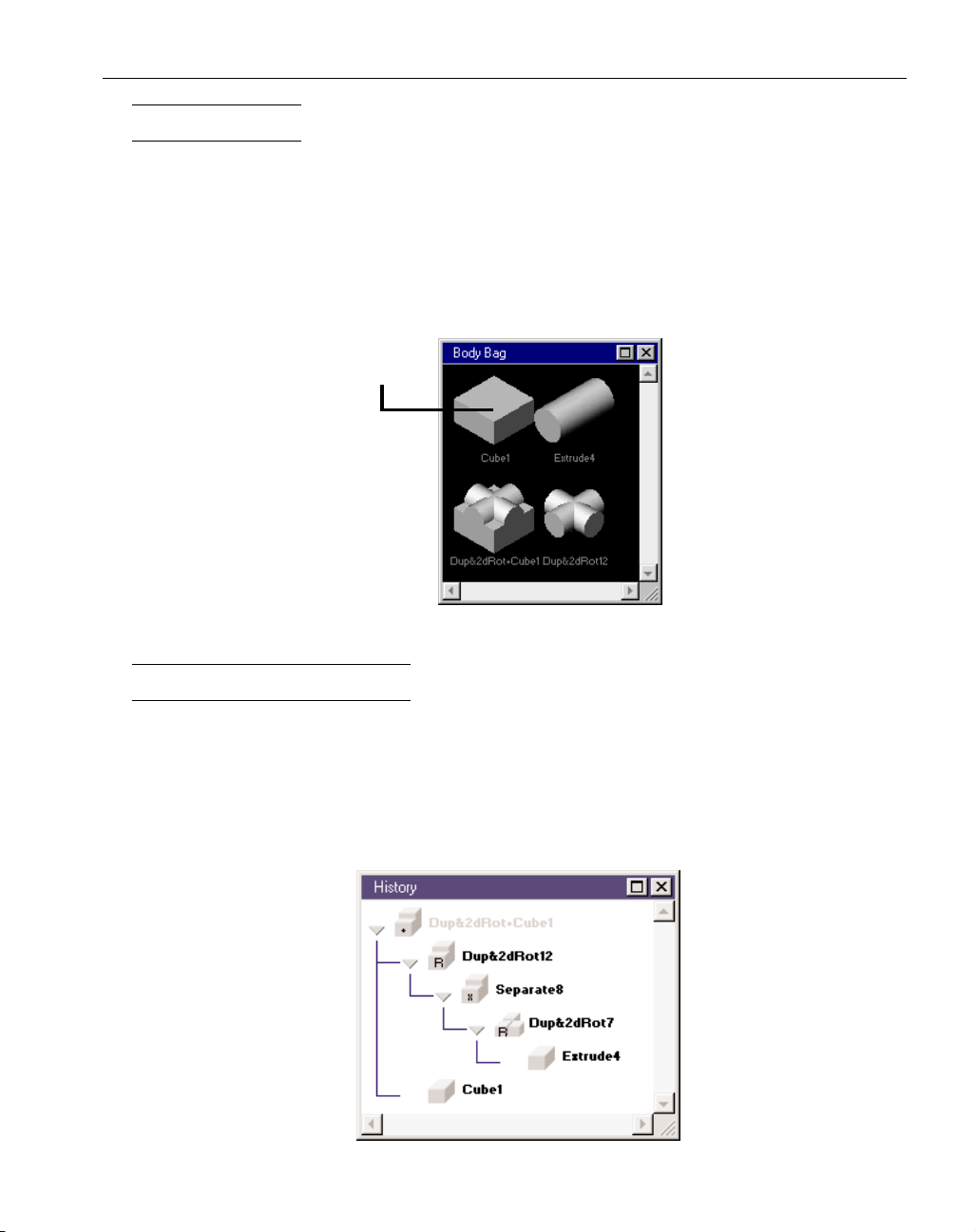
BODY BAG
Bodies and sheets can exist in the drawing window or the Body Bag. The Body Bag is used to
store bodies and surfaces in order to keep the main drawing window uncluttered. Double clicking on
a body or surface will place it in the Body Bag and remove it from the drawing window. The Body
Bag context menu also contains items for selecting and placing bodies and sheets in the Body Bag.
When bodies are in the Body Bag, they are represented as icons. These icons can be dragged, selected, re-sized, or renamed. They act very similar to standard system icons. The body and sheet icons
can either be double clicked or dragged out of the Body Bag in order to get the objects back in the
drawing window.
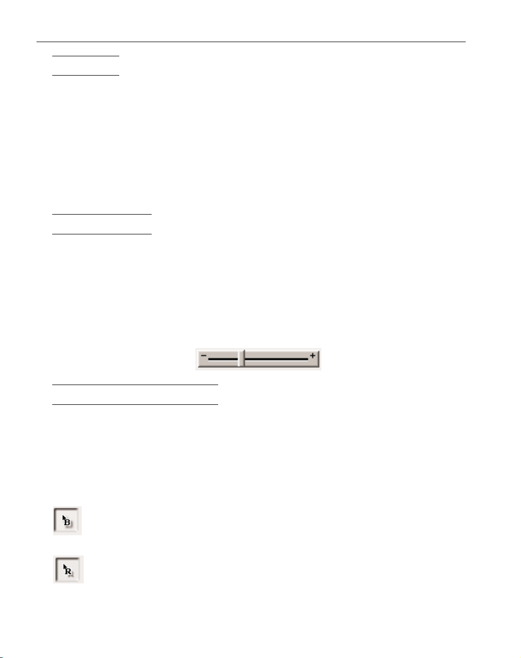
HISTORY DIALOG
The History dialog displays the history tree for any selected body. All of the bodies that were
used to create the selected solid or sheet will appear in the history tree, even if they are no longer
active bodies. Any of the bodies listed in black in the history tree can be brought back to the workspace and modified. To bring a body back into the workspace from the history tree, double-click on
the cube next to the name of the body. The arrows at the branches of the history tree can be clicked
on to expand that branch of the history. If a body is grayed out in the history tree, it is an active
body. Active bodies are in the workspace, either the main drawing window or the Body Bag.
GFK-1709 Interface
◆
3
Body Bag Icon
Page 8
COLORS
The system uses colors to graphically display different items. The color scheme listed below is
for the rendering of objects by the solid modeler. For a list of other colors used by the system, refer
to the Geometry Creation and Mill Module Manuals.
Object Rendering
Gray Unselected Bodies
Light Blue Unselected Sheets
Yellow Selected Bodies and Sheets
Dark Blue Stock Bodies
Red Constraint Bodies and Sheets; Fixtures; Inside of Sheets
SLIDE BARS
Slide bars are an interface item used in a few of the dialogs when a specific value is not necessarily required. The user can either type in a value or use the slide bar. For example, when designating the chord height, either in the Graphics Preference dialog or the Properties dialog, the user may
simply want to make the rendered image of a solid finer or courser. Moving the slider left towards
the plus sign (+) will make the values larger by given increments. Likewise, moving the slider
towards the negative sign will make the values smaller. When the slider is moved, the numeric values are updated according to the movement. For the Chord Height, the slide bar's numeric values
range from .0001" to .1" and the metric equivalents.
POINTER MARKERS
Pointer markers are interface items that are used to designate particular items that are necessary to perform certain operations. The pointer markers are contained within a bounding box in each
of the dialogs. In order to place a marker, the user can drag the marker from its box in the dialog
and place it on an item, or at a particular location in the workspace. To remove a marker, select the
marker in the workspace and drag it back to its bounding box in the dialog.
These pointer markers are found in the Sweep dialog and the Variable Radius Rounding dialog.
B-pointer marker: The Sweep dialog contains a B-pointer marker, which allows the user to
designate the base curve of the swept body.
R-pointer marker: The Rounding dialog contains an R-pointer marker, which allows the user
to specify different radius values along a single edge when performing a variable radius
blending operation.
◆
SolidSurfacer User Manual GFK-1709
4
Page 9

CHAPTER 2
:
Modeling
INTRODUCTION TO MODELING
This chapter contains reference information on the modeling functions contained in the system.
This first section provides a brief introduction to terms and concepts used in solid modeling. There
is also a glossary which provides additional terms that are used throughout this manual and the software.
DEFINITIONS
The terms and definitions provided below are used to describe objects and elements used by
the solid modeler.
Body: A body is the term used for the solid objects created by the system. Each body is a single
object composed of faces and the area enclosed by the faces. Bodies have volume. Bodies are used
as the building blocks for creating part models.
Sheet: A sheet is the term used for surfaces created or imported by the system. A sheet is an object
composed of faces, but a sheet has no volume or thickness associated with it. It is only composed of
its surface faces.
Face: A face is one surface of a body or sheet. Faces are surfaces that have knowledge of the surfaces
that surround them. For example, one side of a cube would be considered a face. Each face is
bounded by loops. A simple face is bounded by 1 loop.
Loop: A loop is a series of connected edges that outline a face.
Edge: An edge is a curve/line between two faces. A body must have two faces connected at every
edge. [More than two faces at an edge produces a non-manifold solid. The solid modeler cannot perform the necessary calculations on non-manifold solids, and therefore will produce an error message
if operations create non-manifold solids.]
Vertex: A vertex is an endpoint of an edge.
SOLID MODELING
Modeling is the process of defining a part’s shape and dimensions on a computer. Common
types of modeling include wireframe modeling, both 2D and 3D, surface modeling and solid modeling. Solid Modeling is the method of defining a part as a solid object rather than as a wireframe or
collection of surfaces. The process of solid modeling involves using graphically disjunct objects
(bodies and sheets) and combining, modifying, and manipulating them to create the final part model.
A solid model completely identifies any point in space as inside or outside of the model.
The process of solid modeling starts with the creation of a simple body referred to as an atomic
or primitive body. A body is made up of faces and the space enclosed by those faces. A face is a single surface, but a surface that has knowledge of the other surfaces that are connected to it. Examples
of an atomic body include a sphere, a cube, a revolved or extruded 2D shape, etc.
The basic operations, often referred to as Boolean operations, are to add, subtract or intersect
these simple bodies to create a new, distinct body. Each time a Boolean operation is performed, the
result is always a single object. In this way solid modeling allows the user to work with single
objects rather than hundreds of surfaces. When solid modeling, no user input is required to determine the sections of the bodies to maintain or remove. The solid modeler automatically trims off
GFK-1709 Modeling
◆
5
Page 10

unneeded portions, or adds new portions, handling all faces. One Boolean operation may create any
number of new faces on the resulting solid.
Surfaces can also be created by the solid modeler. The solid modeler creates an object called a
sheet. A sheet is similar to a body in that it is made up of faces. A face is a single surface. However,
a sheet does not have any volume the way a body does. A sheet is only made up of faces, whereas a
body is composed of the faces as well as the space enclosed by the faces. One way to think of it is
that a sheet is similar to an infinitely thin gauge balloon while a body is more like a bowling ball.
BODIES
A body is the modeling entity that represents a solid. A body is represented as a single object,
not as a complex collection of surfaces. When a body is created, it is graphically displayed as a solid
object. The system allows the user to view the body as a wireframe, however the wireframe representation cannot be selected and acted upon using any of the functions in the system. It can simply
be viewed. In order to perform any type of operations on the body, such as Boolean operations or
rounding, the body must be viewed as a solid object. The system draws bodies in gray.
The operations of adding, subtracting and intersecting bodies require that two bodies be selected. When these operations are performed, the result is a new, single body composed of the two, previously distinct bodies.
When selected, bodies become yellow. Clicking on a body selects it. Selecting a body indicates what object(s) compose the single body. A single body may contain disjunct objects, which are
objects that are not connected or touching. Disjunct objects contained in a single body are called
lumps. Bodies containing lumps or multi-lump bodies can be separated to create multiple, separate
bodies. The easiest way to tell if disjunct objects are lumps or separate bodies is by selection.
The system defaults to create multi-lump bodies rather than multiple bodies. Creating multilump bodies rather than multiple bodies provides for more efficient part creation due to a shorter
history tree. Also, splitting multi-lump bodies into any number of multiple bodies is more efficient
than adding bodies because bodies can only be added two at a time.
SHEETS
A sheet is the modeling entity that represents a surface. A sheet contains more information than
a surface in that a sheet has knowledge of the neighboring surfaces that surround it. A sheet is represented as a single object. It is composed of faces. Sheets may have one face or several faces. A face
is a single surface. Sheets do not have any thickness or volume. A sheet is the graphical representation of a surface or collection of surfaces.
There are surface modeling tools contained in the system for creating sheets and modifying
sheets. These functions are located in the Surface Modeling palette. The sheet creation functions
include planar sheets, revolved sheets, lofted sheets, Coons patch sheets, swept sheets and sheets
created from selected faces. There are also functions such as Stitch, Unstitch and Trim/Untrim contained in the Surface Modeling palette that are very useful when working with sheets. The sheet creation tools are primarily intended to be used with surface files that are imported rather than creating
complete part models using sheets and surface modeling techniques. The recommended method for
modeling a part is using the solid modeling tools.
When surface files are imported, each surface entity is brought in as a single faced sheet.
These sheets can be modified as necessary to complete the part model or can be machined directly.
◆
SolidSurfacer User Manual GFK-1709
6
Page 11
PRIMITIVES/ATOMIC BODIES
A primitive or atomic body is a simple, non-divisible body; a body that is not built from other
bodies. Atomic bodies do not have a history tree. All solid models start from at least one atomic
body.
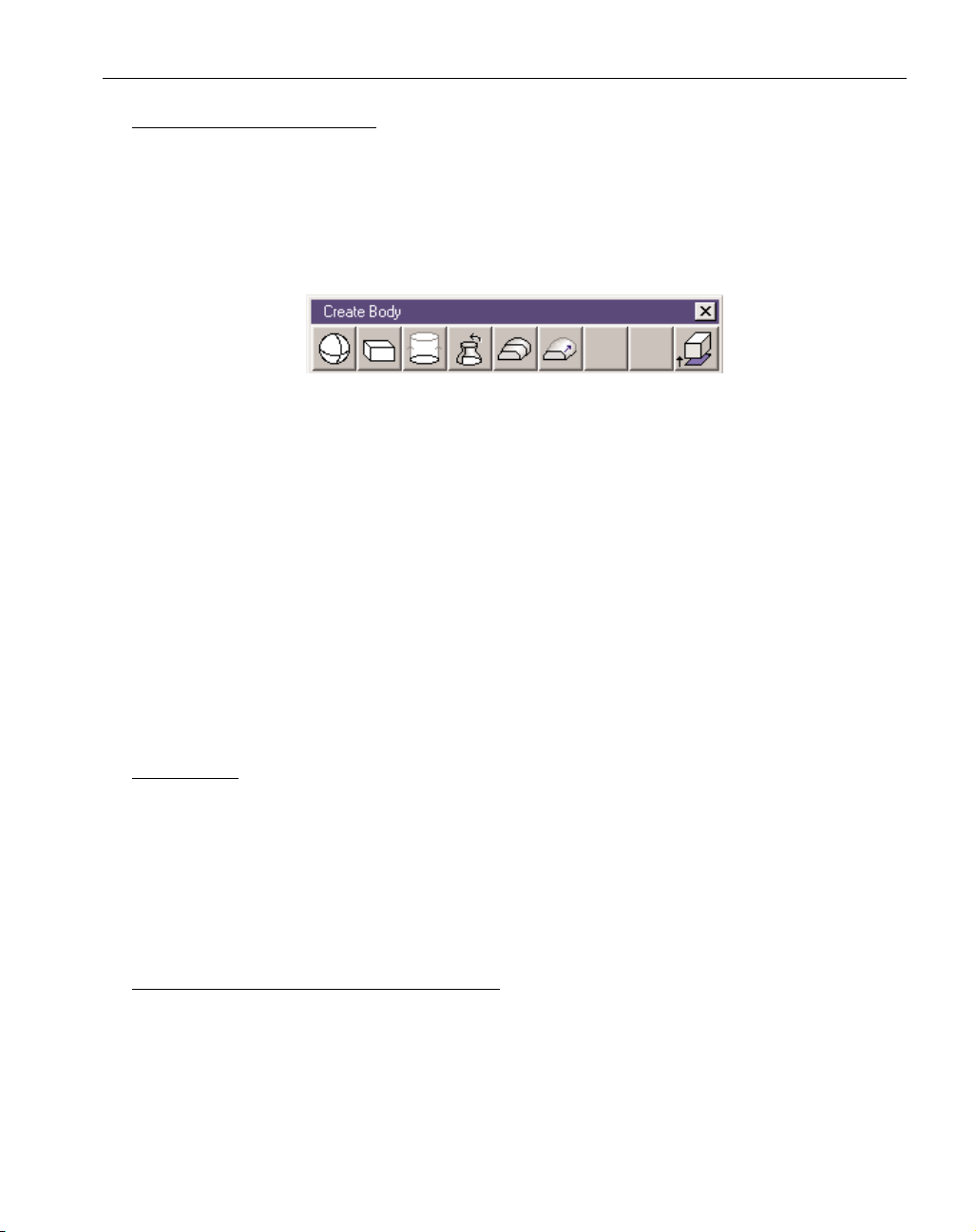
Atomic bodies are created using the functions contained in the Create Body palette which is
accessed by clicking on the Create Body button in the Solid Modeling palette. The Solidifying functions which convert sheets to solid bodies are also contained in the Create Body palette. Solidified
sheets are considered atomic bodies as they have no history tree associated with them.
1. Sphere: A ball or globular solid.
2. Cuboid: Any type of rectangular solid.
3. Extruded Body: A 2D (in HV) closed shape extruded along the depth axis.
4. Revolved Body: A 2D shape, either open or closed, revolved around either the horizontal or
vertical axis, a specified number of degrees.
5. Lofted Body: Lofted bodies are created by selecting a series of closed shapes that will be
blended together using selected alignment points. Lofting is also referred to as skinning or
blending.
6. Swept Body: Swept bodies are created by selecting base curve geometry and drive curve
geometry. The base curve acts as the spine determining the overall contour of the swept
body and the drive curve(s) designate the location and shape of the body.
7. Solidified Sheet: There are several options for solidifying sheets into bodies. They include:
Cap, Extrude, Offset and Solidify Closed Sheets.
WORKSPACE
Active bodies and sheets exist in the workspace. The workspace consists of the drawing window, which is the main portion of the screen and the Body Bag. Bodies and sheets must be active in
order to perform any modeling functions, such as Boolean operations. Bodies and sheets that only
exist in the history tree are considered dormant bodies. Because the solid modeler always creates
single bodies from any operation, the component bodies are removed and made dormant to simplify
the modeling process and control the file size. Dormant bodies can be retrieved using the History
dialog.
WORKGROUPS AND COORDINATE SYSTEMS
Bodies and sheets are NOT contained in workgroups. They are drawn in either the Body Bag
or the workspace, regardless of the current workgroup.
Bodies are assigned a coordinate system which is based on the current CS when the body was
created. Some of the modeling functions, such as extrusions and revolved bodies, are CS specific
meaning that the current coordinate system is used to create the body. Other modeling functions,
such as lofting, are not dependent on the current CS. Regardless, a body is assigned a coordinate
system.
1 2 3 4 5 6 7
GFK-1709 Modeling
◆
7
Page 12

Coordinate Systems can be modified into the proper orientation by selecting components of a
body or sheet. There are two categories of CS alignment, plane through geometry groups and plane
normal geometry groups. Planes can either be aligned through selected geometry or normal (perpendicular) to selected geometry. With bodies and sheets, the plane through geometry groups include
planar edges and planar faces; the plane normal geometry groups include an edge and a point, and a
face (planar or non-planar) and a point. For further information on these subjects, please refer to the
Advanced Milling manual.
BOOLEAN OPERATIONS
Boolean operations are used to combine two entities (either bodies or sheets or some combination of the two) to create a new, single body or sheet. The Boolean operations contained in the system are addition, subtraction and intersection. Boolean operations are destructive, in that the initial
two bodies selected for the Boolean operation are deleted, and only the resulting body remains
active in the workspace. The deleted bodies used in the Boolean operation become dormant bodies
and can be retrieved from the History tree. Non-destructive Booleans can be performed by holding
down a modifier key when performing the operation. The modifier key depends on the selection
made for keyboard shortcuts in the Interface Preferences. If the Alternate Shortcuts option is selected, hold down the Ctrl key to perform non-destructive Boolean operations. If the Windows Shortcuts
option is selected, hold down the Alt key. Non-destructive Booleans will generate the new body and
place the original two bodies used in the Boolean operation in the Body Bag. The following
Boolean operations are supported by the system.
• Addition (Union): Combine the volume of two bodies. Select two bodies and add them
together. The resulting body will be a new single body composed of the two selected bodies.
If the two selected bodies were disjunct (not touching), the resulting body will be a multi-lump
body.
• Subtraction (Difference): Remove the volume of one body from another body. Select two bod-
ies and subtract them. The resulting body will be the first body minus the second body. The
order of selection determines which body is kept and which is subtracted out. The first body
selected is kept and the second body selected is subtracted out.
• Intersection: Keep the common volume between two bodies. Select two bodies and intersect
them. The resulting body will be the volume that is common to the two bodies selected.
HISTORY OF SOLIDS AND SHEETS
The system maintains the history of all solid bodies and sheets that are created using the solid
modeling functions contained in the system. When models are imported in either the Parasolids or
SAT format, the history is not imported.
The History dialog allows the user to access any body that went into the construction of the
selected solid. By giving the user access to the history of a model, changes can be made to an earlier
step in the modeling process allowing for changes to easily be incorporated to the final model without having to start over from scratch.
Every solid except atomic bodies have history trees which contain information on the “parents”. "Parents" is the term used to describe the bodies or sheets that were used to create the select-
◆
SolidSurfacer User Manual GFK-1709
8
Page 13
ed body or sheet. Solids may have one parent, as in cases of rounding or slicing, or two parents as in
the case of Boolean operations. Bodies removed from the workspace as the result of a Boolean operation are maintained in the history tree. Bodies contained in the history tree are considered dormant
bodies, while bodies in the workspace are active bodies. Operations such as rounding or any of the
Boolean functions, can be performed on active bodies only.
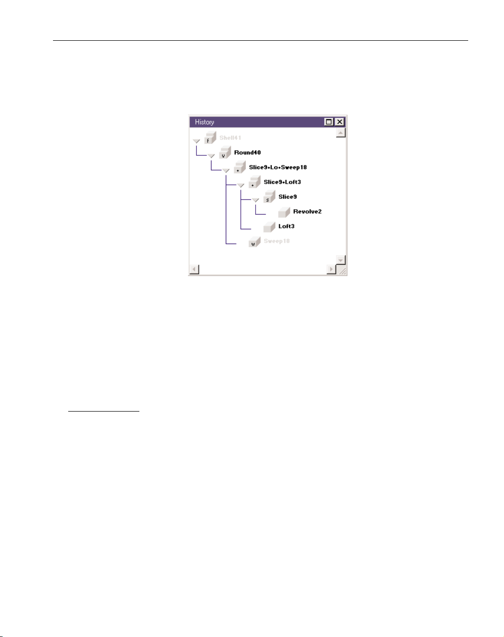
The History dialog is structured in a hierarchical format where the selected body is at the top
and all other bodies used to create it are found below in steps or branches. Double clicking on the
cube icon next to the name of a body will make that body active; it will be brought back into the
drawing window. In order to make modifications to a body contained in the history tree and have
those changes be incorporated into the existing history tree, the Recreate function must be used. The
Recreate and Rebuild functions are described in the following section.
The History dialog is accessed from the Body/Sheet context menu by right mouse clicking on
the body or sheet.
RECREATE MODE
Rebuilding a solid incorporates any changes made to bodies that were used to create that solid.
These bodies are referred to as parent bodies. Recreate allows the user to change a parent body.
Recreate must be used for changes that the user wishes to incorporate into the rebuilding of a solid.
Bodies can be modified using the Recreate function of the software. The context menu
accessed when a body is right mouse clicked contains the Recreate item. When Recreate is selected,
the system goes into Recreate mode.
When in Recreate mode, the body selected to be recreated is drawn in red and placed in the
Body Bag. Recreate mode can be exited by selecting the body drawn in red, or selecting the Exit
Recreate item from the body context menu. If applicable, the parent body or bodies that were used
to create the body to be recreated become active and appear in the drawing window. The function
button originally used to create the body will be outlined in red. All original data will be restored.
Following are some examples of what can be done using the Recreate function.
• Change the data for an atomic body. For example, change the radius of a sphere.
• Recreate an atomic body from different geometry or modified geometry. The geometry
should be changed prior to entering Recreate mode.
GFK-1709 Modeling
◆
9
Page 14

• Change the type of atomic body that was created. For example, a sphere can be made into a
cuboid.
• Change the selected parents used in a Boolean operation.
• Change the type of Boolean operation that was performed.
Recreate only affects the creation of the selected body. To change its parents they must be
brought back from the History dialog and then the parent bodies can be recreated.
REBUILDING SOLIDS
Because the system maintains the history of solids and sheets, it is possible to modify earlier
steps during model creation and rebuild the final model. Any changes made can be incorporated into
the final model using the Rebuild function. This level of associativity is very useful when working
with complex models that would take considerable time to rebuild from scratch if changes are necessary.
To rebuild a model follow the steps outlined below.
1. Bring an earlier body back from the history tree.
2. Make modifications to that body using the Recreate function.
3. Rebuild the body by selecting the Rebuild item from the Solids menu.
The Rebuild function reprocesses the history tree. Any changes made to a body or sheet contained in the History tree will be incorporated into the rebuilt model. The only way to make a modification to an existing body without changing the name and reference of that body is to use the
Recreate function. The Rebuild function is not undoable which means that once a model has been
rebuilt, it cannot be changed back to its previous state.
Rebuild is useful when working with imported solid models. As an example, let's say you start
with an imported Parasolids file. You build a mold base body from this model. Changes are made to
the original model provided. The new model is imported into the system. To incorporate the new
changes, you would recreate the mold base by selecting the new body instead of the old one and
performing the Boolean operation. Then select the final body and rebuild it.
FACETING
Rendering is the process of displaying a picture of a model on the screen. When bodies and
sheets are rendered, they are faceted. Facets are small planar surfaces that compose the rendered
model. The more facets that are drawn, the closer the model resembles the actual mathematical
model and the more time it takes the system to render the model. Faceting affects the quality of the
rendered image of bodies and sheets. It also affects overall system performance and speed. The
faceting chord height should be set at a value that balances the quality of the model with system per-
formance. The faceting tolerance has NO affect on machining tolerances, only on the rendered image on the
screen. The tolerance used for surface machining is set in the Process dialogs and is labeled as the
Surface Tolerance. It is this specification which designates how closely the toolpath will follow the
surface.
The number of facets used to render a model is determined by the chord height. A chord is a
straight line that joins any two points on an arc or circle. The chord height is the distance from the
chord to the arc or circle (Figure 2.1). The smaller the chord height, the closer the facet will be to
the arc or circle resulting in a better rendered image of the body or sheet. (This is a 2D description
◆
SolidSurfacer User Manual GFK-1709
10
Page 15
of chord height, the system uses a 3D chord height for the faceting of bodies and sheets, but the
general idea is the same.)
Figure 2.1
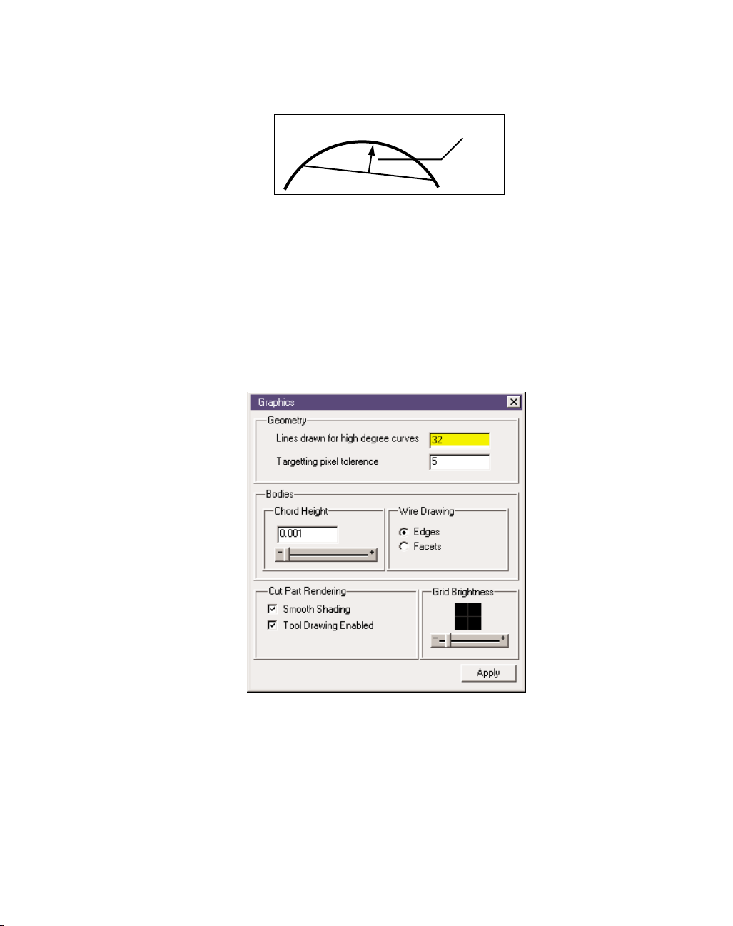
The system uses an overall faceting chord height which is applied to the entire part model. The
overall part chord height will be applied to all bodies and sheets that are created using the system’s
modeling functions, as well as any models that are imported. The overall part chord height is
entered in the Graphics Preference dialog (Figure 2.2) accessed from the Preferences submenu
under the File menu. The chord height is found in the Bodies section of the Graphics dialog. The
default chord height is .01". A number can be entered in the text box or the user can move the slider
in the + or - direction for a finer or coarser tolerance.
The Apply button must be depressed in order to change the facet tolerance for selected bodies
and sheets, as well as setting the value for new bodies.
Figure 2.2: Overall Part Chord Height in Preferences Menu
A different faceting chord height can be applied to individual bodies and sheets. The Properties
dialog (Figure 2.3), accessed by right mouse clicking on a body or sheet, contains a chord height
value which will only be used to facet the selected body or sheet.
GFK-1709 Modeling
◆
11
Chord Height
Page 16
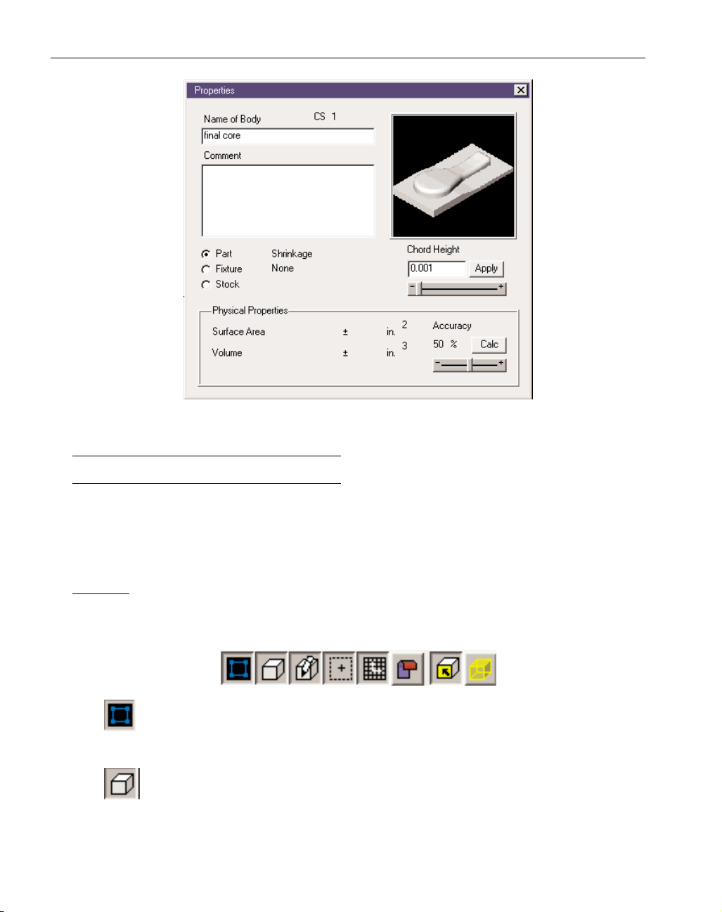
Figure 2.3: Individual Part Chord Height from Properties
MODELING REFERENCE
This section provides functional descriptions of the modeling capabilities contained in the system.
These modeling functions are put to practical application in the modeling exercises which provide
tutorial style learning. It may be best to start with the modeling exercises and refer to the reference
section when something is unclear.
TASKBAR
The taskbar is always displayed on the screen below the menu bar. The buttons in the taskbar
affect the drawing and selection of objects in the drawing window. Each button can either be turned
on or off; depressed is on, raised is off.
Show Geometry: When this button is depressed (on), geometry will be displayed in the
drawing window. If off, geometry will not be drawn. The geometry still exists, it is just
not displayed on the screen.
Show Solids: This button is very similar to the Show Geometry button, except it affects
bodies and sheets. When turned on, all bodies and sheets will be displayed in the workspace. If off, all body and sheets will not be displayed. This button does not affect the
drawing of objects in the Body Bag.
◆
SolidSurfacer User Manual GFK-1709
12
Page 17
Render/Wireframe: When this button is on, bodies and sheets will be rendered as solid
objects. If off, bodies and sheets will be displayed as wireframe drawings, not rendered
objects. The wireframe drawing will display either the edges or the facets of bodies and
sheets depending on the selection made in the Graphics Preference dialog.
Show Stock & Origin: When this button is on, the stock outline and origin will be drawn
on the screen. This button replaces the Show Stock & Origin in the View menu.
Show CS Grid: When this button is turned on, the CS grid and axis markers for the current coordinate system will be drawn on the screen. The CS grid will always be drawn
at the depth of 0. The axis markers will always be displayed on top of any body or
sheet. This button replaces the Show CS Grid item in the View menu.
Indicate Sheet Side: This button is for use with sheets. It differentiates the outside and
inside of a sheet by displaying it in different colors. The outside of the sheet will
remain the standard blue that is assigned to all sheets, while the inside will be dis-
played in red. The outside of a sheet is the side from which the positive direction of the
surface normal is projecting outward. The negative direction of the surface normals are projected out from the inside of the sheet. The sheet side is important when performing such functions as offsetting sheets or solidifying sheets using either the offset or extrude option. This is
due to the fact that sheets are offset or extruded in the positive direction of their surface normal. It is possible to toggle the inside and outside of a sheet, using the Toggle Sheet Side item
in the Modify menu.
Face Selection: When this button is depressed, the system will be in face selection mode,
which means that when bodies or sheets are clicked on to be selected, only the face
will be selected, not the entire body or sheet.
Edge Selection: When the Edge Selection button is depressed, the edges of all sheets and
bodies in the workspace will be displayed. These edges can be selected. An edge is the
curve between two faces. In order to select edges for such functions as blending, geometry
extraction, body unstitching, etc., the user must be in Edge Selection mode. Also, when using
the stitching function, Edge Selection mode is useful for viewing the external edges of a
model. If an edge is double-clicked, the system will attempt to select an entire loop that contains the selected edge. This edge selection will stop when it has more than one good choice at
a vertex. In some instances, it may take a few double clicks on different edges to select an
entire loop, but it is still much faster than attempting to select edges one at a time.
GFK-1709 Modeling
◆
13
Page 18
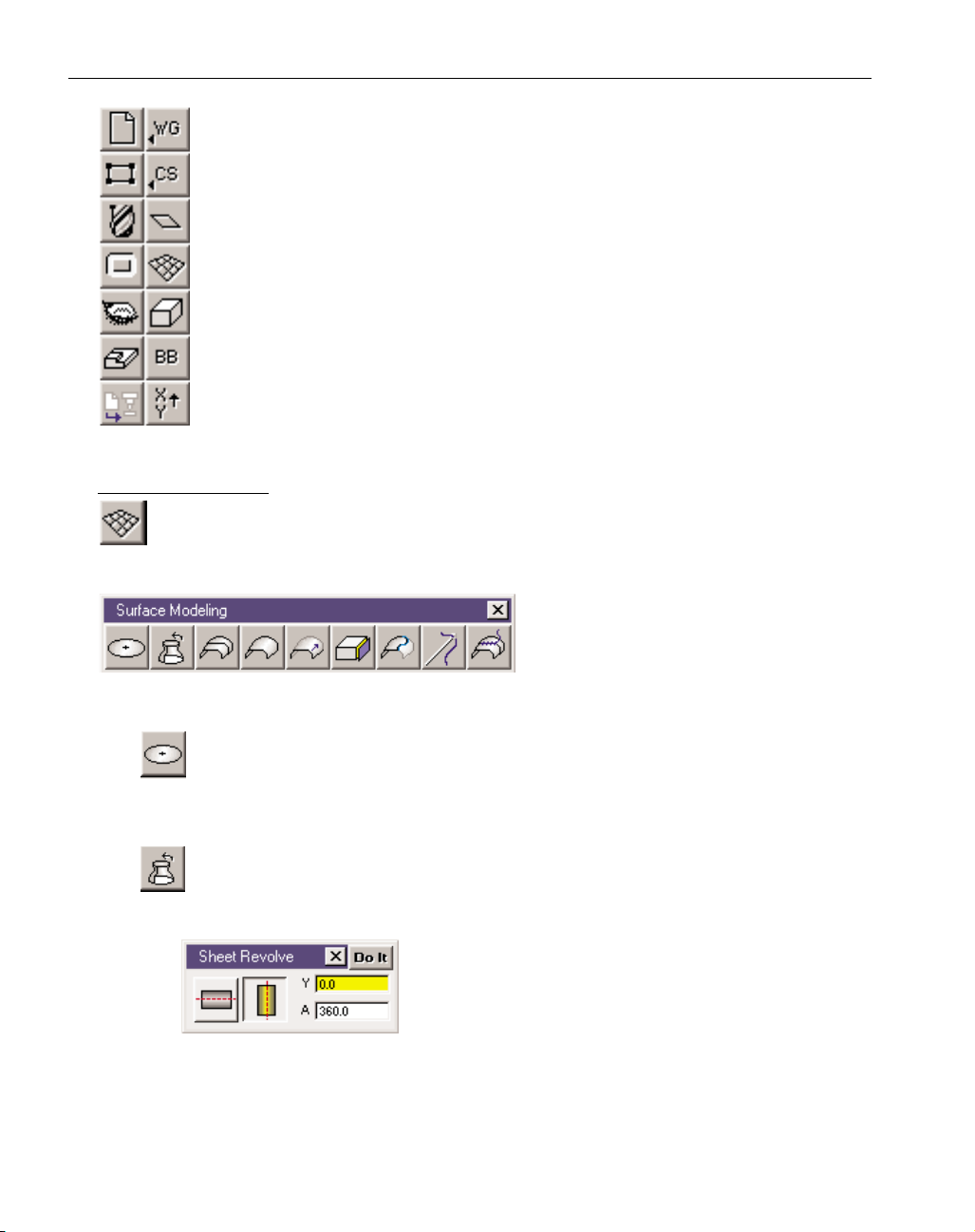
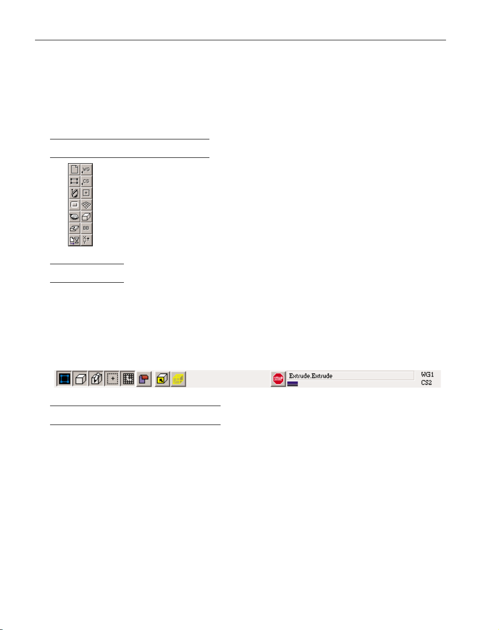
Top Level palette: The Top Level palette contains 14 buttons when the Level 2 interface
is in use. The Level 2 Interface must be used in order to access the SolidSurfacer functionality. All of the surface modeling and solid modeling functions contained in the system are accessed from the Top Level palette. The Body Bag, which is used as a storage
place for bodies and sheets, is also accessed from the Top Level palette. The other Top
Level palette buttons function as they do when using the Production Modules of the
software.
SURFACE MODELING
Surface Modeling button: Depressing this button brings up the Surface Modeling palette,
shown below, which is used to create sheets. Surface modeling and sheets are primarily for
working with imported surface files, and are not generally required for building bodies.
Surface Modeling palette: This palette provides
various methods for creating sheets, including planes, revolved sheets, lofted sheets,
Coons patch, and stitching separate sheets
together.
Plane button: This button is used to create planes. With no geometry selected, this function will create a flat, planar sheet based on the current coordinate system. Selecting a
closed, planar shape will create a sheet bounded by the selected geometry and based on
the plane of the selected geometry.
Revolve button: Depressing this button, brings up the Sheet Revolve dialog which allows
users to revolve a shape around the horizontal or vertical axis by a specified number of
degrees, creating a sheet.
Sheet Revolve dialog: Select an open, terminated shape or a
closed shape to be revolved. The axis buttons specify which
axis the selected shape will be revolved about. If the horizontal axis is selected for the axis of revolution, a vertical
value must be entered to specify the position of the revolution axis. Likewise, if the vertical axis is the axis of revolution, a horizontal value must
be entered to specify the position of the revolution axis. The value entered in the A text
box is the angle, specified in degrees, the selected shape will be revolved around the
selected axis. A positive angle value will revolve the shape in a counter clockwise
◆
SolidSurfacer User Manual GFK-1709
14
Page 19
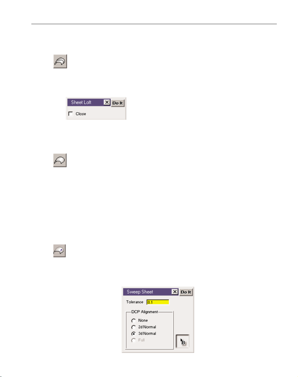
direction and a negative angle in a clockwise direction based on the positive axis of
revolution.
Loft button: Depressing this button accesses the Sheet Loft dialog which allows users to
create a sheet through a series of open or closed shapes. The system will blend all the
selected shapes into a smooth sheet. Sheet lofting produces ruled surfaces when
only two shapes are selected and sculptured surfaces when three or more shapes are
selected.
Sheet Loft dialog: Select a series of shapes to be blended into a
smooth sheet. These can be closed or open, terminated
shapes. The shapes act as the cross-sections through which
the final sheet will be created. The system will blend the
selected shapes into a sheet using C0 points (corners) as alignment points. If the Close
button is checked, the system will attempt to blend the first and last shapes together to
form a closed sheet.
Coons Patch button: This button creates a sheet called a Coons patch through either
three or four selected open, terminated shapes.A Coons patch is a surface type that
uses boundary shapes, typically splines, and blends a smooth surface between them.
Either three or four shapes must be designated as boundary shapes. Each shape can be any size
or orientation as long as the endpoints are coincident (in the exact same location in X, Y and
Z) and each shape is continuous and does not contain any sharp corners. The selected shapes
represent the boundary of the sheet.
In some cases, connected splines or features can be selected to create a Coons patch.
Also, if trimmed splines are imported that do not have coincident point at the edges, a Coons
patch can be created providing the ends of each trimmed spline are coincident. If there are
more than 3 or 4 line segments, but the connected splines have three or four distinct corners,
often times a Coons patch surface can be created.
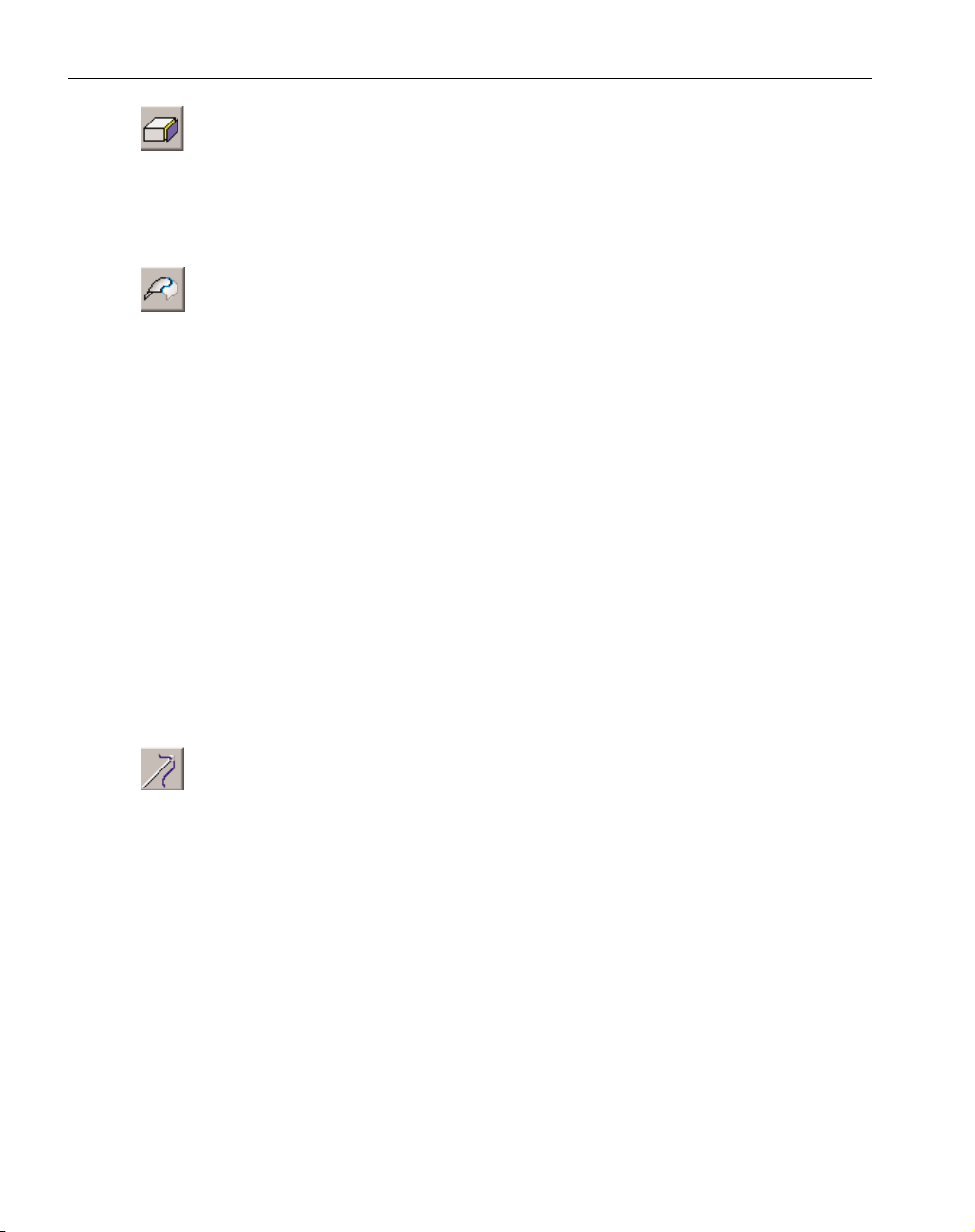
Sweep Sheet: The Sweep Sheet function is nearly identical to the Sweep Body function
which is described in the following Solid Modeling section. The only difference
involves the alignment rules for the drive curves. Swept sheets do not use alignment or synch
points, selected on the drive curves, to determine how the drive curves will be blended together. Only one alignment point per drive curve needs to be selected for the Sweep Sheet function.
Refer to the Sweep Body section for additional information.
GFK-1709 Modeling
◆
15
Page 20
Sheet from Face: This option creates a sheet from the face of a body or sheet. A face is
one surface of a body or sheet and is bounded by an edge loop. Using the Face
Selection mode accessed from the taskbar, users can select individual faces of either a
sheet or a body. Selecting a face or faces and clicking on this button will create a sheet based
on the face which will be bounded by the edge loop of the selected face. Neighboring faces
will produce stitched faces in the resulting sheet.
Trim/Untrim Sheets: The trim and untrim functions are both performed with this button
depending on the entities selected when the button is depressed. If a sheet and geome-
try are selected, the system will attempt to perform the trim operation. The trim function breaks a single sheet into two separate sheets at the selected trim geometry. The geometry
selected for the trim operation must completely cut the selected sheet into two pieces. If the
geometry does not lie on the selected sheet, the geometry will be projected onto the selected
sheet and the trim operation will be performed.
If only a sheet is selected, the system will attempt to untrim. The Untrim function
only works with single face sheets. The edge loop is what bounds the underlying surface definition into a finite bounded surface. The Untrim function, in essence, removes the bounding
edge loop so that the underlying surface definition replaces the selected surface. The
untrimmed surface will be bounded by the stock. This is useful when working with imported
IGES files that are not stitching or solidifying due to edge loops of neighboring surfaces not
joining within the specified tolerance. In that case, the user can select the problem sheet,
untrim it to create the underlying surface definition and then trim that surface with the extracted edges from neighboring sheets.
Holding down the Alt key when the Untrim/Trim button is depressed will perform
both the trim and untrim operations at once. The system will untrim the selected one face sheet
and trim that sheet to the selected geometry in one step, never attempting to create a valid face
from the untrimmed surface.
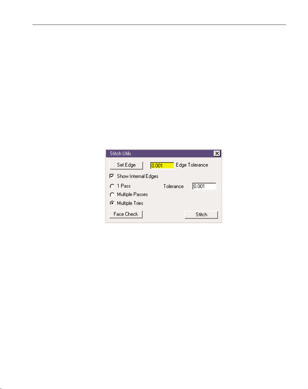
Stitch Sheets: The Stitch Utilities dialog, accessed by clicking on the Stitch Sheets but-
ton, provides different methods for stitching sheets together, as well as providing tools
to analyze stitched sheets. In order to stitch sheets, the user must select all the sheets to be
stitched, choose a stitching method from the Stitch dialog and click on the Stitch button.
Sheets are stitched at their edges. When surface files are imported into the system,
each surface is represented as a single faced sheet. A face is a trimmed surface with an edge
and knowledge of neighboring surfaces. An edge is the trim curve that bounds a face. For
sheets to successfully stitch to their neighbors, the edges of these sheets must align with each
other within a specified tolerance, otherwise there are holes or gaps and adjoining sheets that
are separated by a gap cannot be stitched.
In order to view edges, the system must be in Edge Selection mode which is accomplished by depressing the Edge Selection button in the taskbar. The Show Internal Edges
checkbox provides a method for only viewing the external edges of a part. The internal edges
are edges that can be viewed from the inside of the model looking out, while the external
edges are viewed from the outside. The external edges are the edges that need to be stitched
together. After performing a stitching operation, the only external edges that will be visible are
the edges that could not be stitched together because of the tolerance gap. All stitched edges
become internal edges.
◆
SolidSurfacer User Manual GFK-1709
16
Page 21
Once the problem edges have been identified, if the gap is large, the user can build a
sheet using Coons patch or another Surface Modeling tool to fill the hole. Often times the gaps
are small and can be solved by setting a different tolerance. The user can apply a looser tolerance to select edges. This is accomplished by selecting the problem edges, entering the looser
tolerance in the Edge Tolerance text box, and clicking on the Set Edge button. Applying a dif-
ferent edge tolerance to certain edges often aids the system in stitching together all of the
sheets.
There are three methods of stitching offered in this dialog: 1 Pass, Multiple Passes
and Multiple Tries. Each of these methods uses the tolerance value entered in the dialog. The
tolerance can be thought of as the maximum gap that can exist between the edges of two sheets
that the system will still stitch together. For example, the edges of two adjoining sheets are
.0001" apart. If the tolerance set is .0001" or greater, the two sheets will be stitched together
and the result will be a single sheet. If the tolerance is less than .0001", the two sheets will not
be stitched together and remain two separate entities. The minimum tolerance is set by the system and is .00002mm or .00000079". The tolerance specified by the user cannot be less than
this value.
1 Pass: When the 1 Pass option is selected, the system will attempt to stitch all selected
sheets at the given tolerance. The system will take one pass at the specified tolerance in
this attempt. The system will analyze each sheet, its neighbors and its edges and if they
fall within the tolerance, stitch the sheets together. If all edges stitch together at this tolerance into a single closed sheet, the system will solidify the sheets, creating a solid body.
Otherwise, the result will be a multi-faced sheet composed of all of the sheets that could
be stitched together.
Multiple Passes: When this option is selected, the system will attempt to stitch together all
selected sheets by performing a series of single passes. The system will begin at the minimum tolerance which is .00002mm and attempt to stitch the sheets at that tolerance. The
tolerance entered by the user provides the maximum tolerance that the system will go to
in its attempt to stitch the sheets. Multiple passes will be taken at incremental tolerance
steps ranging from the minimum tolerance (set by the system) to the maximum tolerance
(set by the user). On each pass the system will stitch together all the sheets it can at that
tolerance and then proceed to another pass at the next tolerance, attempting to stitch any
remaining sheets. The progress bar, located on the right side of the taskbar, displays the
number of sheets remaining to be stitched and the tolerance being used on the current
GFK-1709 Modeling
◆
17
Page 22

pass. When all of the passes have been completed, if the sheets stitched together into a
single closed sheet, the system will automatically solidify the sheets, resulting in a solid
body. Otherwise, the result will be a multi-faced sheet or sheets.
Multiple Tries: This option is similar to the Multiple Passes option in that it takes incremen-
tal passes ranging from the minimum tolerance, which is .00002mm, to the maximum tolerance, which is the Tolerance value entered in the Stitch dialog. The system will attempt
to stitch all the sheets together at each tolerance increment, starting over from scratch
after each pass that does not stitch together all the selected sheets. The system is looking
for the smallest single tolerance that will stitch the entire part. This is similar to taking a
series of one pass steps and undoing after each one. The stitching process will stop when
all the selected sheets have been stitched together into a single sheet even if this occurs
before the maximum tolerance is reached.
Face Check: Clicking on the Face Check button will perform a face validity check on the
selected sheets. This is identical to the face validity check that is run when the Check
Body Validity item is selected from the Solids Tools menu. Check Body Validity is
described in the Machining reference section. The face check produces an error message
for each invalid face and also deselects the problem faces. It is useful to run a face check
if stitching has failed to identify problem areas before attempting to stitch again. When a
face fails the check, it must be deleted and re-created in order for future stitching
attempts to be successful.
Unstitch Sheets: This function will unstitch selected faces of a sheet or unstitch faces of
a body to create sheets. A face is a single surface of a sheet or body which is bounded
by an edge loop. Multiple, adjoining faces can be selected to be unstitched. The faces will be
unstitched at the edge loop which bounds the selected face or faces. Faces can be selected
when the Face Selection button in the Taskbar is depressed. The following pictures illustrate an
example of an unstitching operation (Figure 2.4). The first row of pictures shows a single,
multi-faced sheet with the edges displayed to differentiate between the faces of the sheet. In
the second row multiple, adjoining faces are selected to be unstitched. Again the result will be
two sheets, unstitched at the edge separating the selected faces from the non-selected faces.
◆
SolidSurfacer User Manual GFK-1709
18
Page 23
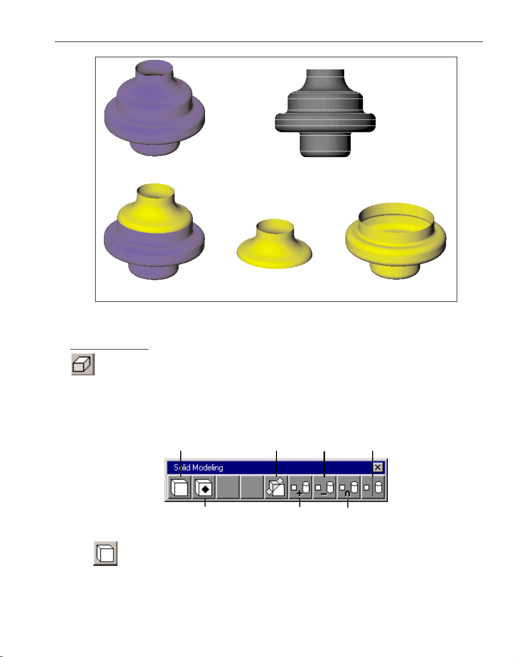
Figure 2.4: Example of Unstitching Sheets
SOLID MODELING
The Solid Modeling palette is accessed by clicking on the Solid Modeling button in the Top
Level palette. All of the modeling functions that are used with solids are accessed from this
palette. The first button accesses the Create Body palette which provides options for creating atomic
or primitive bodies. The second button accesses the Advanced Solid Modeling palette which provides for such functions as offsetting and rounding. The remaining buttons in the Solid Modeling
palette, include Slicing, Adding, Subtracting, Intersecting and Separating which are all options that
provide for various interactions between solids and sheets.
Create Body button: Depressing this button accesses the Create Body palette which provides various methods for creating atomic bodies and solidifying sheets into bodies.
Atomic bodies or primitives are non-divisible bodies in that they were not created from
any other bodies. They are the starting blocks for creating solid models.
GFK-1709 Modeling
◆
19
Original Sheet Edges of sheet which separate the faces
Selected face to be unstitched Resulting Sheet Resulting Sheet
Create Body
Advanced Modeling
Slice
Subtraction
Addition
Seperate
Intersection
Page 24
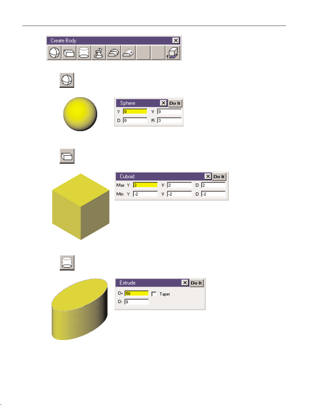
Create Body palette: This palette pro-
vides options for creating atomic bodies in a variety of methods. Each
method is described below.
Sphere button: Depressing this button brings up the Sphere dialog which allows
users to create spherical bodies.
Sphere dialog: Enter the H, V, D (hori-
zontal, vertical, and depth) coordinates of the centerpoint of the sphere
and a radius value. Click on the Do It
button to create the sphere.
Cuboid button: Depressing this button brings up the Cuboid dialog which allows
users to create cubes, rectangular bodies and slabs.
Cuboid dialog: Enter
a minimum and
maximum
horizontal, vertical
and depth value to define the volume of the cuboid. These values
will be measured from the origin of the current coordinate system.
The labels used in the dialog may vary when the current coordinate
system aligns with one of the primary planes. The labels X, Y and Z
will be used instead of H, V and D.Click on the Do It button to create the cuboid.
Extrude button: Depressing this button brings up the Extrude dialog which allows
users to create a body by selecting a closed shape and extruding it along the depth
axis.
Extrude dialog: Select a 2D (in
H and V) closed shape. The
shape can be extruded along
the depth axis of the current
coordinate system in the positive and/or negative direction based on the values entered in the D+
and D- text boxes. These text boxes may be labeled X, Y or Z if the
current coordinate system aligns with one of the primary planes.
The extrusion starts at the depth location of the geometry selected
to be extruded. Click on the Do It button to create the extruded
body.
◆
SolidSurfacer User Manual GFK-1709
20
Page 25
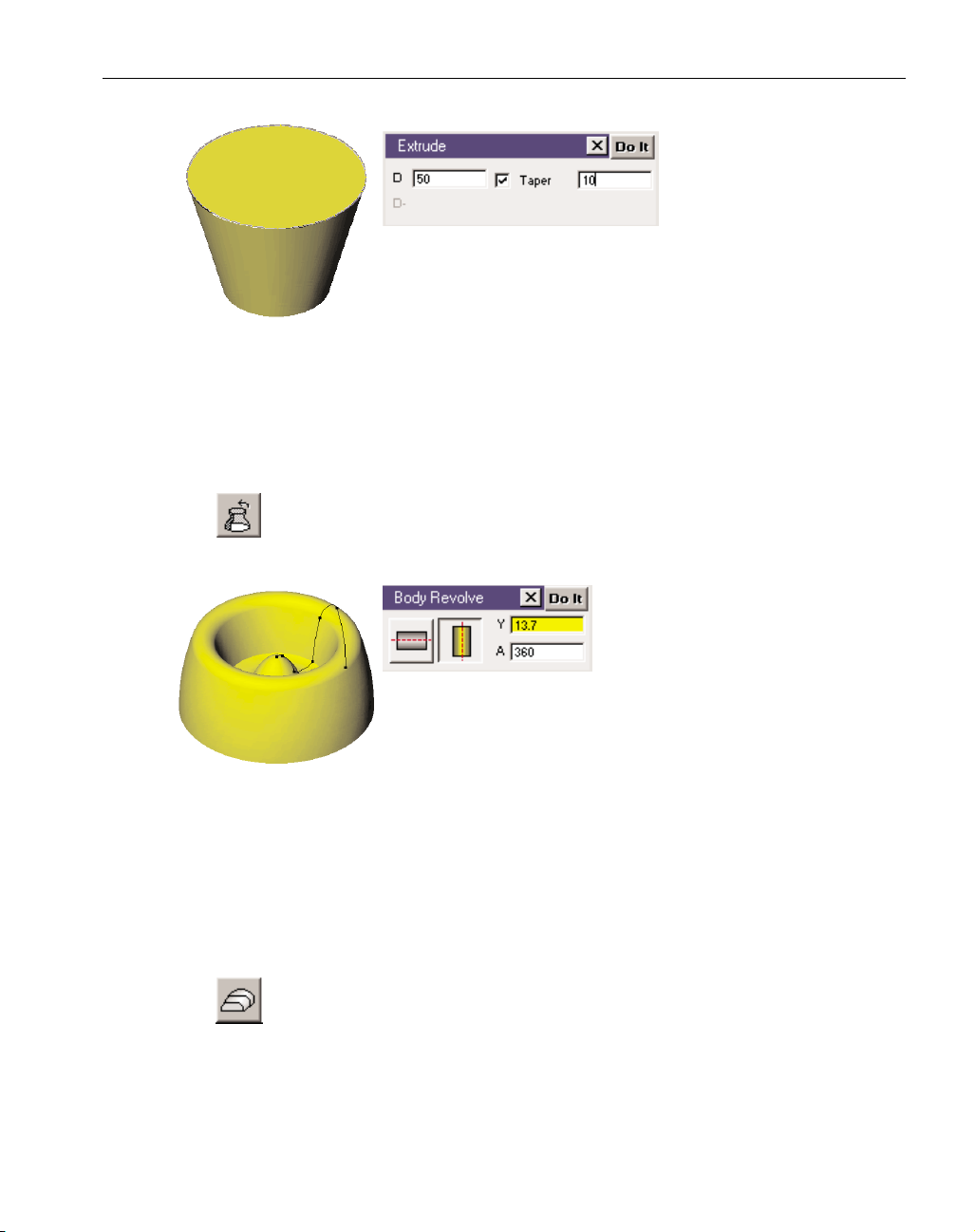
TAPERED EXTRUSIONS
A taper can be put on an
extruded body. The value
entered for the taper specifies the angle of the taper.
When doing an extrusion
with a taper, the extrusion can only be done in one direction along
the depth axis in order to properly calculate the taper on the body.
When the Taper box is activated, the negative depth specification
will become grayed out. A negative value can be entered for the Z+
value so that the shape can be extruded along the negative direction of the depth axis. Negative
angle values can also be entered for the taper amount. When extruding a body, the shape
selected to be extruded is duplicated along the depth axis by the amount specified. When doing
an extrusion with no taper, the offset shape is an exact duplicate of the original shape. When
creating an extrusion with a taper, the offset shape is going to be larger or smaller (depending
on if the taper is positive or negative) than the original shape.
Revolve button: Depressing this button accesses the Body Revolve dialog which
allows users to revolve a shape a specified number of degrees around either the
horizontal or vertical axis to create a body.
Body Revolve dialog: Select an open,
terminated shape or a closed shape to
be revolved. The selected shape must
be an open, terminated shape, rather
than a closed shape, in order to revolve 360° about an axis position
of 0. In other words, there cannot be a line on the axis of revolution,
or revolving will fail because it will produce self intersecting edges.
The axis buttons designate whether the shape will be revolved
around the horizontal or vertical axis of the current coordinate system. If the horizontal axis is
selected for the axis of revolution, a vertical value must be entered to specify the position of
the revolution axis. Likewise, if the vertical axis is the axis of revolution, a horizontal value
must be entered to specify the position of the vertical axis that will be the revolution axis. The
value entered in the A text box is the angle, specified in degrees, the selected shape will be
revolved around the selected axis. A positive angle value will revolve the shape in a counter
clockwise direction and a negative angle in a clockwise direction based on the positive axis of
revolution.
Loft button: Depressing this button brings up the Body Loft dialog. Lofting is also
referred to as blending or skinning.
GFK-1709 Modeling
◆
21
Page 26

Body Loft dialog: Select a series
of closed shapes to be blended
into a body. These selected
shapes define the crossections
of the resulting lofted body. The shapes should be selected
by choosing points on each shape that will act as alignment
or synchronization points. The system will break up the
section of the shape between synch points into an equal
number of segments and create a face (surface) by match-
ing each segment. The synch points on each shape will match up in the finished lofted body.
To achieve the best results when lofting, select all relevant points to act as synch points. If the
shapes selected have the same number of corners, one synch point per shape can be selected
and the system will blend the lofted body using the corners as synch points. A corner is defined
as the non-tangent intersection between two features. When selecting synch points on the
shapes, either select all synch points per shape in the same order or select the first synch point
on all shapes then the second, etc. The system looks at the selection order for each shape. If the
Close button is turned on, the system will attempt to blend the first and last shapes together
into a closed body. Click on the Do It button to create the lofted body.
In the Figure 2.5, three closed shapes are selected to be lofted. The top picture shows the
shapes selected to be lofted. The second set of pictures show synch points selected, one has
one synch point per shape, the other six synch points per shape. The third set of pictures show
the lofted bodies created from the shapes. The body created from the shapes with one synch
point selected blends the shapes using the four corners of each shape because the shapes have
the same number of corners. The body created from the shapes with six synch points selected
blends the body based on all of the synch points selected allowing the user more control over
the body that is generated.
◆
SolidSurfacer User Manual GFK-1709
22
Page 27
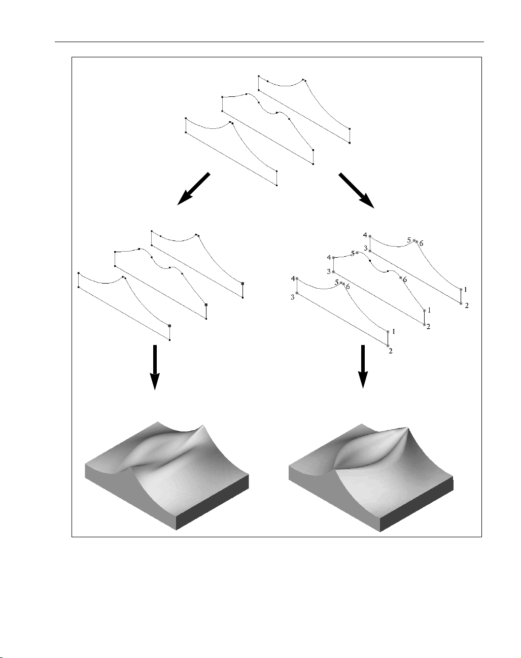
Figure 2.5: Example of the use of synch points in lofting
GFK-1709 Modeling
◆
23
Curves Selected for Lofting
1 Synch Point Selected
1
Lofted Body
6 Synch Points Selected
1
1
Lofted Body
Page 28
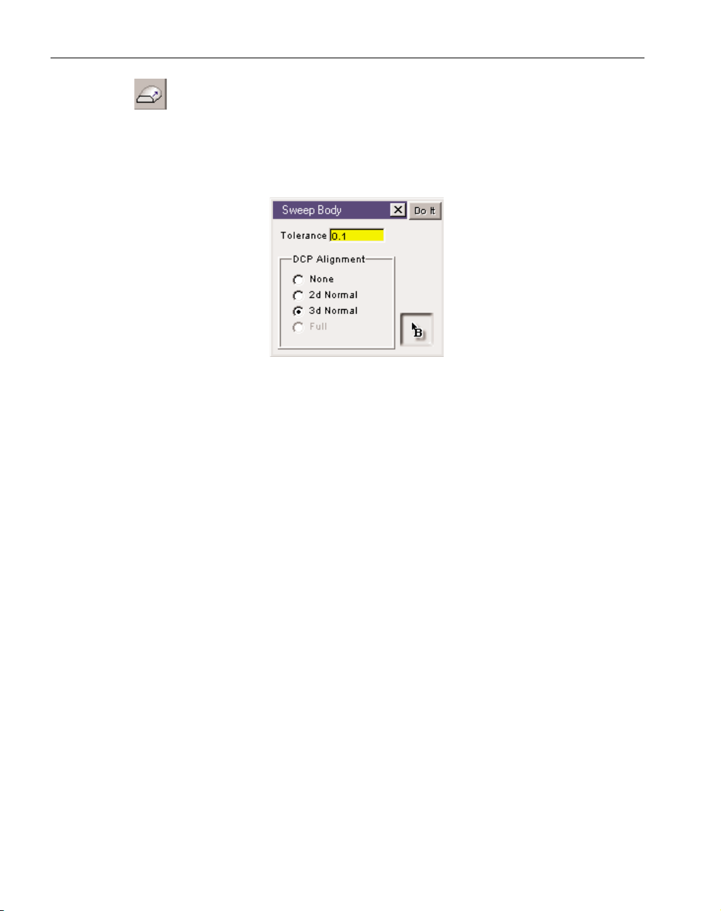
Sweep Body: The Sweep function is located in the Create Body palette. It pro-
vides options for creating swept bodies. A swept body is created by selecting a
base curve, which defines the spine or edge of the desired swept body, and a drive
curve(s) that designates the location and shape of the swept body by defining the cross
sections. The Sweep function supports one base curve and a maximum of two drive
curves. The tolerance value specifies how closely the generated swept body will be to the
"true" swept surface.
Base Curve: The base curve can be a 2D or 3D curve and must be either a closed shape or
an open, terminated shape. It should also be defined in the exact 3D location for the
desired swept body. The B-pointer marker, located in the Sweep Body dialog, is used to
designate the base curve. The B-pointer can be dragged from its box in the dialog and
dropped on the geometry to be used for the base curve. It can be removed in the same
manner, dragging it from geometry back to its box in the Sweep dialog. The location of
the B-pointer marker on the base curve has no affect on the resulting swept body.
Drive Curve: The drive curve(s) are 2D curves that define the cross sections of the swept
body. The drive curves must be defined in the correct 3D location for the desired swept
shape. The system supports a maximum of two drive curves. Following is a list of rules
regarding drive curve creation.
1. Drive curves must be planar.
2. All drive curves must be closed shapes and selected in the appropriate order for
the desired swept body. Open, terminated shapes can be used for the drive curves
when these open shapes can be capped by a single plane.
3. Select drive curves by choosing alignment points on each of the shapes.
• Alignment points must be connectors or terminators on the drive curves.
• A minimum of one alignment point must be selected for each drive curve.
• If more than one alignment point is selected, all corner connectors (non-tangent intersections) must be selected
• If only one alignment point is selected for each shape, corner connectors will
automatically be aligned. In this case, each shape must have the same number
of corner connectors or the sweeping operation will fail.
• The same number of alignment points must be selected on each shape.
• Full circles have a default alignment at 12:00, in their respective planes. This
allows the user to select circles for the drive curves without needing to create and
select alignment points. If full circles are selected for the drive curve without
alignment points selected and the resulting swept body is not the desired result,
create terminators or connectors on the circles in order to control alignment.
◆
SolidSurfacer User Manual GFK-1709
24
Page 29

Sweeping Plane: The Sweeping Plane is the current coordinate system when the Sweeping
function is performed. The Sweeping Plane affects the DCP Alignment options when the
2d Normal or 3d Normal choices are selected. The sweeping plane also determines the
CS to which the resulting swept body will be assigned.
DCP Alignment: The DCP Alignment options determine the alignment of the drive curve
plane in reference to the base curve; how the drive curve will be swept around the base
curve. There are three options: None, 2d Normal and 3d Normal.
None: The selected drive curve determines the orientation of the drive curve plane.
All the frames used for the drive curve plane will be parallel to the plane of the
selected drive curve. The drive curve is simply translated along the base curve, but
not rotated in any way.
2d Normal: The selected drive curve will be rotated around the sweeping plane normal vector so that it is perpendicular to the base curve in the sweeping plane.
However, the drive curve will not remain normal to the base curve as the base curve
moves in Z (or the depth of the current CS). Another way to think of this is that the
vertical axis of the drive curve plane always stays parallel to the depth axis of the
sweeping plane. The alignment is locked.
3d Normal: As in the 2d Normal case, the selected drive curve will be rotated around
the sweeping plane normal vector so that it is perpendicular to the base curve in the
sweeping plane, and it will follow the base curve as it changes in depth. Another
way of describing this is that the horizontal axis of the drive curve plane will lie in
the sweeping plane and be normal to the base curve at every point.
Following are examples that provide a series of pictures intended to illustrate the different
types of alignment and sweeping options. The first example (Figure 2.5a, b & c) illustrates the differences between the None and 2d Normal alignment options, while the second example (Figure
2.6a, b & c)deals with the difference between the 2d and 3d Normal options. The third example
(Figure 2.7a & b) provides an illustration of one base curve, which is acting as a spine, and two
drive curves.
GFK-1709 Modeling
◆
25
Page 30
EXAMPLE 1: NONE VS. 2D NORMAL ALIGNMENT
Figure 2.5a: Base curve and drive curve geometry
Figure 2.5b: DCP Alignment: None
Isometric View Top View with Drive Curve cross sections
◆
SolidSurfacer User Manual GFK-1709
26
Page 31

Figure 2.5c: DCP Alignment: 2d Normal
EXAMPLE 2: 2D VS. 3D NORMAL ALIGNMENT
Figure 2.6a: Base curve and drive curve geometry
Side View Isometric View
Isometric View Top View with Drive Curve cross sections
GFK-1709 Modeling
◆
27
Page 32

Figure 2.6b: DCP Alignment: 2d Normal
Figure 2.6c: DCP Alignment: 3d Normal
Side View Side View with Drive Curve cross sections
Side View Side View with Drive Curve cross sections
◆
SolidSurfacer User Manual GFK-1709
28
Page 33

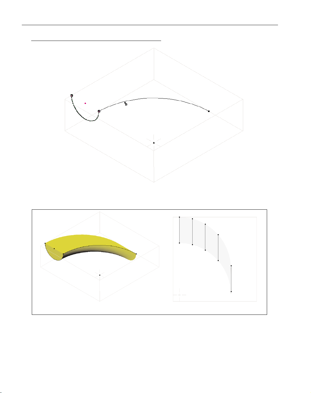
EXAMPLE 3: ONE BASE CURVE AND TWO DRIVE CURVES
Figure 2.7a: Base Curve and Drive Curve Geometry
Figure 2.7b: Resulting Swept Body
Top View Isometric View
Top View Isometric View
GFK-1709 Modeling
◆
29
Page 34

Solidify button: This button accesses the Solidify dialog which provides options for creating bodies from sheets. It is often useful to solidify sheets into bodies to reduce part
complexity and so that solid modeling functions can be performed. However, it is not
necessary to solidify sheets in order to machine them. Sheets can be machined directly without
being solidified or stitched together.
Solidify dialog: This dialog contains four options for
converting sheets into solid bodies. To solidify a sheet,
select the desired option in this dialog, select the sheet
and click on the Do It button. The first three options
can only be used to change a single sheet into a body.
The Solidify Closed Sheets option can be used on mul-
tiple sheets. Each method is described below.
Cap: The Cap option creates a body from an open sheet by creating planar surfaces at any open
ends of the selected sheet. The enclosed area is filled in to create the solid body. In order to use
the cap option to solidify a sheet, the sheet selected to be capped must only require planar surfaces to provide closure of open ends of the sheet. Figure 2.8 illustrates the capping function to
solidify a sheet.
Figure 2.8 : Example of solidifying a sheet using the Cap option
Extrude: The Extrude option creates a solid body by extruding a selected sheet along the depth
axis of the current coordinate system. The sheet can be extruded in the positive or negative
direction along the depth axis. The user enters a value which specifies how far along the depth
axis to extrude the sheet. Entering a negative value will extrude the sheet along the negative
direction of the depth axis. When performing an extrusion, the sheet selected to be extruded is
duplicated along the depth axis by the amount specified and the area between these sheets is
filled in to create a solid body. In order to use the extrude option to solidify a sheet, the sheet
selected to be extruded cannot overlap itself or fold over. Also, the extrude axis (depth axis of
the current coordinate system) can not hit the sheet in more than one place and cannot be parallel to the edge of the sheet. Figure 2.9 illustrates extruding a sheet in order to solidify it.
◆
SolidSurfacer User Manual GFK-1709
30
Sheet Solidified Body
Page 35

Figure 2.9: Example of solidifying a sheet using the Extrude option
Offset: The Offset option creates a solid body by creating an offset sheet of the sheet selected to
be solidified at a specified distance and filling in the area between the original sheet and the
offset sheet to create a solid body. The definition of an offset is that every point on the offset
sheet will be normal (perpendicular) to a point on the original sheet. Offsetting can be thought
of as rolling a ball with a diameter the size of the offset amount along the sheet.
When using the Offset option, the user specifies a Max and/or Min value that acts as
the offset amount. The sheet selected to be solidified acts as the 0 reference point for the Max
and Min values. These values can be positive or negative. The sheet selected to be solidified
will be offset in one direction by the Max value and in the other direction by the Min value.
Figure 2.10 illustrates the offsetting function to solidify a sheet.
Figure 2.10: Example of solidifying a sheet using the Offset option
Solidify Closed Sheets: The Solidify Closed Sheets option creates a solid body by filling in the
volume enclosed by adjoining separate sheets. The sheets selected do not need to be stitched
together in order to use this solidify option. There can be no holes or gaps between the adjoining sheets to be solidified. The accuracy for closure must be .001" in order for Solidify Closed
Sheets to create a solid body. This option provides the same functionality as the stitching
options which are accessed from the Surface Modeling palette.
GFK-1709 Modeling
◆
31
Sheet Solidified Body
Sheet Solidified Body
Page 36

ADVANCED SOLID MODELING PALETTE
The Advanced Solid Modeling palette is accessed from the Solid Modeling palette by
depressing the Advanced Modeling button. The functions included in this palette include
Shelling and Offsetting, Blending/Rounding, Body Unstitch and Drafting a body. Each function is described below.
Offset/Shell button: This button is located in the Advanced Solid Modeling palette and
accesses the Offset-Shell dialog. Within the Offset-Shell dialog, there is an Offset button and a Shell button. Depressing one of these buttons accesses the respective function. Each
is described below.
Offset: The Offset function can be performed on bodies, sheets and individual
faces. The Offset function will grow or shrink a body or face by the specified
Offset amount. Positive offset values will make the selected entities larger; neg-
ative values, smaller. Both bodies and faces can be offset and multiple bodies
and faces can be offset at one time. To offset a body or face, select the body or face(s), enter an
offset amount and click on the Do It button. It should be noted that the original body selected
to be offset is replaced by the offset body. The original body can be brought back from the
History tree if necessary. Figure 2.11 provides an example of offsetting an entire body, while
Figure 2.12 illustrates offsetting only selection faces.
Figure 2.11: Offset Body
Original Body Offset Body
◆
SolidSurfacer User Manual GFK-1709
32
Offset
Shell
Page 37

In Figure 2.11, the original body is a solid canister and the offset body is enlarged by a given
offset amount. Note the change in the size of the fillet at the top of the bottle; it is a much
smaller fillet than on the original body due to the fact that the system must extend the unoffset
neighbors to intersect. This example would fail to offset if the offset amount was greater than
the size of the fillet. In Figure2.12, only selected faces are offset and the unselected faces
"grow" in order to provide for the offset.
Figure 2.12: Offset Selected Faces of a Body
The offset function can also be performed on sheets. A sheet has two sides, an inside
and an outside. The outside of a sheet is defined as the side from which the positive direction
of the surface normals are projecting outward. The negative direction of the surface normals
project to the inside of the sheet. When offsetting sheets, the location of the selected sheet will
be moved in the direction of its positive surface normals by the specified offset amount. Sheets
are offset to the outside of the sheet. The outside and inside of a sheet can be determined by
turning on the Indicate Sheet Side button in the taskbar. When this button is depressed the system will display the outside of sheets as blue and the inside of sheets as red.
Original Body Faces Selected to be Offset
Resulting body with Offset Faces
GFK-1709 Modeling
◆
33
Page 38

In certain instances, the offset function will not succeed because the specified offset
amount creates excessive topology changes. Topology is the term in solid modeling for the
manner in which specific faces of a body are positioned relative to each other. Modeling functions that change the shape of a face do not affect the topology, unless the function requires
that a change be made to the way faces connect to one another along their edges. An example
of offsetting that will require excessive topology changes, and therefore will fail, is if the offset
amount is greater than an inside (concave) fillet of the face or body to be offset. The offset
function attempts to extend the unoffset neighbor faces to intersect with the faces that are
being offset. When one or more of the unoffset neighbor faces is tangent to the offset face, no
amount of extension will intersect with the offset face. Therefore the offset function will fail in
this instance.
Shell: The Shelling function creates hollow bodies. The Offset amount entered
specifies the amount the body will be shelled, which is equivalent to the wall
thickness of the resulting hollow body. Entering a negative value for the offset
will shell the body to the inside, meaning that the outside face not be enlarged
to account for the shell amount, remaining in its original position. A positive value will offset
the body to the outside and the body itself will become larger as a result. In this case the inside
of the face of the shelled body is the same as the outside face of the original body. Deselecting
faces on the body to be shelled will create entry holes at those faces. Select a body, deselect
the faces to be removed for entry holes using face selection mode and click on the Do It button
to create the shelled body. It is not necessary to create entry holes, however, if there are no
entry holes on the shelled body it will need to be sliced or modified to see the results of the
shell. Figure 2.13 illustrates an example of a shelling operation which creates an entry hole by
deselecting a face.
Figure 2.13: Example of a Shelling operation
Original Body Body Selected with
Top Face Unselected
Results
◆
SolidSurfacer User Manual GFK-1709
34
Page 39

Blending: The Blending or Rounding function contains options for blending edges of
bodies. There are options for constant radius rounding, variable radius rounding and
constant width chamfering. Figure 2.14 shows which button is used for the different
blending options. The dialog will change slightly depending on the type of blending. In order
to use the blending functions, edges of bodies or sheets must be selected. The system must be
in Edge Selection mode for edges to be viewed and selected. Multiple edges can be rounded at
one time.
Figure 2.14: Blending Dialog
When the Constant Radius button is depressed, selected edges will be rounded
according to the Radius value entered. When the Spherical Corners option is checked, rounding will be applied down each sharp vertex at each corner.
When the Constant Chamfer button in this dialog is depressed, selected edges will be
chamfered based on the Length value entered. The chamfer is calculated by offsetting both
faces joined at the selected edge by the length value specified and then finding the intersection of these offset faces. From the intersection, normals are projected back onto the original
faces. The points where the normals intersect the original faces are the start and end points
of the chamfer.
The Variable Radius option allows users to specify different radii at different locations
along a single edge. This is accomplished using the R-pointer markers which designate the
locations along the edge(s) where the different radius values will be applied.
When an edge is selected to be variably rounded, R-pointer markers will snap to the
vertices of the selected edge. Vertices are the points where two edges meet; they are the corners or endpoints of an edge. Variable Radius Rounding requires that the radius be specified at
every vertex of an edge. Therefore, the R-pointer markers remain attached to the vertices and
cannot be moved. Aside from the radius markers at the vertices, optional R-markers can be
moved from the Blending dialog and placed at any location along an edge. The R-pointers at
the vertices are drawn in gray, while the optional R-pointers are drawn in black. Black pointers
can be moved, gray pointers cannot.
To apply a pointer, click on the R-pointer in the Blending dialog and drag it to a location along an edge. There is no limit to the number of optional R-pointers that can be placed
GFK-1709 Modeling
◆
35
Variable Radius
Constant Radius
Constant Chamfer
Page 40

along an edge. To remove an optional marker, drag it back to its box in the Blending dialog.
Once the markers are placed, the radius values must be entered. When one of the R-pointers is
clicked, it turns red and the radius value entered in the Blending dialog will be applied at that
location. Different radius values can be entered for every R-pointer. Simply select the R-pointer by clicking on it, make sure it turns red, and enter the desired radius value. Once all of the
radius values have been entered, click on the Do It button to create the rounded edge.
There is a Smooth Transition checkbox in the Blending dialog. If it is unchecked, the
system will create a linear or constant rate of change in radius between R-pointer markers.
This will not produce a smooth transition at the R-marker positions, but will produce a uniform
change in radius along the edge. With the Smooth Transition option checked, the system will
produce a variable rate of change in radius that starts slow and ends slow providing for a
smooth transition in the rate of radius change at each of the R-pointers.
The following picture (Figure 2.14) illustrates a variable radius blend. There are Rpointers at each of the vertices (corners) of the selected edge that cannot be moved, and one
additional R-pointer has been added at the midpoint of the edge. The radius values entered for
each of the markers became larger moving down the edge.
Figure 2.14: Example of Variable Radius Blend
Body Unstitch: The Body Unstitch function allows solid models to be broken into com-
ponent pieces or "healed" to remove holes. A body can be thought of as a series of
faces stitched together at their edges into a complete closed shape which is a solid (filled rather
than hollow). Body Unstitch provides a means of removing the stitching along selected edges
to separate a body into component bodies. The system will extend faces along the selected
edges to “heal” the components into valid solid bodies. The primary purpose of the Body
Unstitch function is in working with finished part bodies to create core and cavity bodies for
mold work, or removing holes and other details not needed for certain machining operations.
This is particularly useful when working with models that were imported into the system.
When using body unstitch, either all of one group's faces must be selected or edges must be
selected which will separate all of the original body's faces into two unconnected groups. In
order to select edges, the Edge Selection button in the taskbar must be depressed so that the
edges of a selected body are visible and able to be selected.
◆
SolidSurfacer User Manual GFK-1709
36
Page 41

EXAMPLE 1: UNSTITCHING COMPONENTS
An example of this function is illustrated in the following series of pictures (Figure
2.15). The original body is a sphere with a cylindrical boss. There is an edge where the cylinder intersects the sphere. Selecting this edge and using the body unstitch function will create
two bodies. One will be the sphere, which will not have a hole where the cylinder was previously attached. The other body will be a cylinder, flat on one end, concave spherical on the end
that was initially attached to the sphere.
Figure 2.15: Example of Unstitching
GFK-1709 Modeling
◆
37
Original Body: Sphere with Cylindrical Boss Select edge where components intersect
Resulting Body: Sphere Resulting Body: Cylinder with
sphereical bottom face
Page 42

EXAMPLE 2: HEALING COMPONENTS
Another example of body unstitch involves removing or “plugging” holes in order to
create a mold cavity or to prevent a tool from dipping into a hole intended to be drilled. The
following series of pictures (Figure 2.16) illustrate this aspect of body unstitch. The original
body is a cube with a through hole at its center. The hole has two edges, one at each end where
it exits the cube. To use the body unstitch, select both the edges of the hole and click on the
Body Unstitch button. The two resulting bodies are a cylinder which was the hole and a solid
cube with no holes. In the first example of the sphere with a boss, both bodies were solid to
begin with, not holes. In this example, one of the bodies is completely empty, a hole. The body
unstitch function will detect the case of a hole body and automatically invert that body into a
solid.
Figure 2.16: Example of Unstitching
◆
SolidSurfacer User Manual GFK-1709
38
Original Body: Cube with a through hole Select both edges where hole exits cube
Resulting Body: Hole body, Cylinder Resulting Body: Cube with no holes
Page 43

There are several uses for the Body Unstitch function.
1.Cap holes which are intended to be drilled and do not need to be machined along with
the contour of the model.
2. Remove fillets or chamfers that are unnecessary for machining, or would be more efficiently created using the tool to create the fillet or chamfer. Removing blends on edges
simplifies a model and may provide for faster and more efficient toolpath creation.
3. Create core and cavity molds from hollow models. For example, in creating a cavity
for a bottle, the part model of the bottle is hollow and in order to create a usable mold
cavity by subtracting the part model from a block, the model must be filled/solid on the
inside.
4. Calculate the volume that a bottle or any type of hollow container can hold by using
the volume calculations in the Properties dialog.
5. Use bodies created from the unstitching function to build electrodes for use with EDM
work.
Draft Body: The Draft Body button prompts the Draft dialog which allows users to apply
a draft angle to selected faces of a body. The Draft function is primarily intended for
mold work where draft angles are necessary in order to pull apart a mold and remove the part.
To draft a body, select the faces to be drafted and a reference entity indicating where the draft
will begin, which is usually an edge, enter the draft angle and click on the Do It button.
It is recommended that the draft be applied to the final core and cavity bodies, rather
than the part model that is subtracted or intersected to form the mold. In order to apply a draft
angle, the user must select the faces to be drafted and a reference entity, usually an edge, from
which the draft will start. Multiple faces and multiple edges can be selected and drafted at one
time. In order to select faces and edges, the system must be in Face Selection Mode and Edge
Selection Mode, which are turned on using the respective buttons in the taskbar. The reference
entity acts as the pivot point or origin for the draft angle. Often times the parting line curve
acts as the reference entity. The angle is calculated based on the depth axis of the current coordinate system; the depth axis is the 0 reference. Positive angles will draft the face out in the
direction of the positive surface normal of the face, while negative angles will draft the face in
the negative direction of the surface normal.
The following example (Figure 2.17) shows a body to which a draft angle will be
applied. The top edge of the body and the left angled face are selected as the reference entities
for the draft to be applied to. The draft angle applied is 60° being measured from the depth
axis, which is Z in this case. All measurements for applying a draft are absolute, not incremental.
GFK-1709 Modeling
◆
39
Page 44

Figure 2.17: Example of Draft with one selected face and edge
The second example of adding a draft angle (Figure 2.18) shows the same body as the prior
example. In this case the front top edges of the body and the front face are selected as the reference
entities for the draft to be applied to. The draft angle applied is 15˚ being measured from the depth
axis. Notice in this case, an additional edge and face have been created by the drafting function.
Figure 2.18: Example of Draft with one selected face and two selected edges
◆
SolidSurfacer User Manual GFK-1709
40
Original Part Model Selected Face and Edge Resulting Body
Original Part Model Selected Face and Edges Resulting Body
Page 45

Slice: This function slices selected bodies or sheets into separate entities. Either the current
CS or a selected sheet can act as the slicing entity. When using a sheet as the slicing tool, the
sheet must extend all the way through the target. If a body and sheet are selected when this button is
depressed, the body will be sliced into two separate bodies where the selected sheet intersects the
body. Likewise, if two sheets are selected, the first sheet selected will be sliced where the second
sheet intersects the first sheet. Slicing a body with a sheet is a type of Boolean operation, and therefore, the sheet will be destroyed or deleted once the slicing operation is complete. The slicing function also works if only a body or sheet is selected. In that case, the body or sheet will be sliced with
the current coordinate system. It is recommended that slicing operations be performed as early in the
modeling process as possible due to the fact that coordinate systems and planes act as very big
(potentially infinite) knives when slicing and may slice other entities that should not have been
sliced.
Addition: The Boolean operation of addition provides for sheet-sheet and body-body interac-
tions. Selecting two sheets and performing the addition function will produce a new single
sheet composed of the two selected sheets. The order of selection is not important when performing
additions. In order to add sheets, they must be either coincident or completely non-intersecting.
When two surfaces overlap and all points on one surface also lie on the other surface within the area
of overlap, they are coincident. Non-intersecting sheets and bodies will produce multi-lump sheets
or bodies. The Addition operation cannot be performed with sheet-body combinations. Figure 2.20
provides an example of a Body-Body addition and Figure 2.21 illustrates a Body-Sheet addition.
Figure 2.20: Example of Body + Body results in a single body.
Figure 2.19: Example of Sheet + Sheet results in a single sheet.
GFK-1709 Modeling
◆
41
Page 46

Subtraction: The Boolean operation of subtraction provides for sheet-sheet, sheet-body and
body-body interactions. The order of selection is important when performing subtraction
operations as the first entity (sheet or body) selected will be kept and the second entity selected will
be subtracted from the first. Therefore, the second entity, which is being subtracted out, will be
deleted once the subtraction operation is complete. In order to subtract sheets, they must be either
coincident, intersect at a curve where that curve completely splits the first selected sheet, or be nonintersecting. The Subtraction operation is also commonly referred to as the difference function.
Figures 2.21, 2.22, 2.23 and 2.24 illustrate the different types of interactions between sheets
and bodies when the subtraction operation is performed.
Figure 2.21: Example of Body - Body results in a body which will consist of the volume of the first
body selected minus the volume of the second body selected.
Figure 2.22: Example of Sheet - Body results in a sheet that is further trimmed by the boundaries
of the body that intersect the sheet.
◆
SolidSurfacer User Manual GFK-1709
42
Page 47

Figure 2.23: Example of Body - Sheet results in a multi-lump body sliced at the sheet. This can be
Separated to create two bodies.
Figure 2.24: Example of Sheet - Sheet If the sheets selected are coincident, the first sheet selected
will be trimmed with the second sheet, resulting in a new trimmed sheet. If the sheets selected
were not coincident, but intersect, the result will be a multi-lump sheet sliced at the intersection.
Intersection: The Boolean operation of intersection provides for sheet-sheet, sheet-body and
body-body interactions.When two bodies are selected for an intersection operation, the
resulting body will be composed of the common volume between the two selected bodies. Selecting
two coincident sheets and performing the intersection function will produce a new single sheet
which will be composed of the common area between the two selected sheets. The intersection function can also be performed between a sheet and a body. The result will be a sheet which is composed of the area that it has in common with the selected body. Again, the intersection between the
selected sheet and body must be a sheet, not a curve or point.
GFK-1709 Modeling
◆
43
Page 48

Figure 2.25: Example of Body Intersect Body results in a single body composed of the common volume
between the two selected bodies.
Figure 2.26: Example of Sheet intersect Sheet results in a sheet consisting of the common area
between the two selected sheets.
Figure 2.27: Example of Sheet intersect Body results in a sheet trimmed by the body.
◆
SolidSurfacer User Manual GFK-1709
44
Page 49

Separate: The Boolean operation of Separate provides for the separation of multi-lump bodies
and sheets. Performing the Separate function will break a multi-lump body into the unique
and disjunct bodies it was composed of. Now when selected, only the body clicked on will
be selected, instead of the entire multi-lump body.
GEOMETRY CREATION FROM SOLIDS
Geometry from Solids: This button is located in the Geometry Creation palette. The palette that
it accesses provides options for creating 2D geometry from bodies and sheets. The options
contained in the palette include: Geometry Extraction, Hole Extraction and Parting Line. Each of
these functions is described below.
Geometry Extraction: The geometry extraction function creates geometry from selected edges
of bodies and sheets. In order to view edges of a body or sheet, the system must be in Edge
Selection mode. The Edge Selection button is located in the taskbar. When it is turned on,
all edges of bodies and sheets will be drawn on the screen. These edges can be selected; multiple
edges can be selected at one time. Connected shapes will be created if the selected edges create a
closed loop. Clicking on the Do It button in the Geometry Extraction dialog will create 2D geometry
from any selected edges.
Typically, this function will extract the selected edges as splines or curves. However, if the
resulting spline edge can be converted to lines or circles within the specified tolerance, the extracted
geometry will be lines and circles. The Geometry Extraction dialog allows users to enter a tolerance
which will be used to determine whether selected edges approximate lines and circles within the
given tolerance. A large tolerance value will convert more of the edge splines to lines and circles,
while a tight tolerance will keep the entities as they are defined in the part model. A tolerance of 0 is
recommended when extracting geometry that is definitely a circle or a line.
Hole Extraction: This function is used to create circles from holes in bodies or sheets. This is
very useful when a model contains drill holes. In order to create a drilling operation, points
or circles must be selected. This function allows the user to extract circles from the existing holes on
a model in order to have geometry to select for drilling operations.
When using this function, a body or sheet can be selected and the system will scan the faces of
the selection and find all holes. A hole must have walls which are perpendicular to the current CS.
Additionally, the edge loop of the hole must be either a circle or a spline, it cannot be a polyline
(line segments approximating a circle). When hole extraction is performed, the resulting geometry
GFK-1709 Modeling
◆
45
Page 50

will all be circles. Any hole edge loops which are splines, but fall within the Circularity Tolerance
specified will be extracted as circles. Edge loops which are splines that do not approximate a circle
within the given tolerance will not be extracted. The depth of the extracted geometry will be based
on the bottom of the hole(s), making it easy for the user to determine the depth for the drilling operation.
Parting Line: This function automates the creation of a parting line curve which can be used
to create a parting line surface. A parting line surface is the surface along which a mold
pulls apart. Typically, a mold is pulled apart into two pieces, either two cavities or a cavity
and a core. These two pieces must match and seal perfectly along the parting line surface in order
for the mold to produce the desired part. With simple molds, the parting line is often a simple plane
through the middle of the part. However, there are more complex situations where a planar parting
line will not work.
To use this function, select all the faces that the parting line will be on or select an entire body.
The Parting Line function uses the depth axis of the current coordinate system as the draw axis. The
draw axis is defined as the axis on which the mold will be pulled apart. The parting line curve is the
curve on which the surface normal vector is normal to the draw axis at every point. The Parting
Line function creates 2D geometry which can then be used to create a parting line surface. A good
way to create a parting line surface from parting line geometry is to sweep a straight line along the
parting line geometry, creating a sheet which will intersect the body. The straight line is the drive
curve and should intersect and slightly overlap the parting line geometry which is the base curve.
Once the parting line surface is created, the part model can be subtracted from a cube to create the
mold, and then, sliced with the parting line surface to create the two halves of the mold.
The following series of pictures (Figure 2.28) shows the process of creating a parting line surface by selecting a part model, creating parting line geometry using this function, and then creating
the mold.
◆
SolidSurfacer User Manual GFK-1709
46
Page 51

Figure 2.28: Example of creating a parting line surface to create a mold.
BODY BAG
Body Bag button: Depressing this button brings up the Body Bag dialog. The Body Bag is
used to store bodies during part creation in order to keep the workspace uncluttered.
GFK-1709 Modeling
◆
47
Starting Part Model Parting Line Geometry Sweeping Geometry
Parting Line Surface: swept sheet Mold Block (w/ part model subtracted out)
sliced with parting line plane
Botton half of mold cavity Top half of mold cavity
Page 52

Body Bag dialog: Double-clicking on a body or
sheet in the drawing window will remove the
body or sheet from the drawing window and
place it in the Body Bag. Items that are placed
in the Body Bag are still considered active bodies in that they can be selected, modified,
involved in Boolean operations, involved in
machining selections, etc. When building complex parts requiring many creation steps, it is
necessary to keep the screen as uncluttered as
possible. And because bodies may overlap in
such a way that they are not selectable/accessible, it is often necessary to have another area
where bodies can be displayed. Bodies in the Body Bag are represented as icons which can be
dragged and selected.
EDIT MENU ITEMS
Select submenu: The Select submenu contains Bodies and Sheets items so that users can select only
bodies or sheets in a file. There is also a By Name item which allows users to select entities by
entering their name in the appropriate name in the By Name dialog.
Deselect submenu: The Deselect submenu contains the items Bodies and Sheets so that users can
deselect only bodies or sheets in a file.
MODIFY MENU ITEMS
Shrinkage: The Shrinkage item accesses the Shrinkage dialog which allows users to perform uniform
or axial reductions or enlargements on selected bodies. The Shrinkage range is -10% to 10%. A
selected body can be reduced or enlarged up to 10% of its original size. The Shrinkage function is
designed to be used when creating molds to compensate for shrinkage factors encountered in the
manufacturing process.
◆
SolidSurfacer User Manual GFK-1709
48
Page 53

Toggle Sheet Side: This item is useful when solidifying sheets into bodies using the Offset solidify
option. When sheets are converted into bodies by offsetting, the offset must be calculated from one
side of the sheet or the other. The Max and Min offset values are referenced from one side of the
sheet. To offset the sheet from the other side, select the sheet and then select the Toggle Sheet Side
item.
PREFERENCES
Software preferences are accessed from the Preferences submenu under the File menu.
Graphics Preference: This preference contains settings that affect the graphic display of bodies and
sheets. The overall part chord height is entered in the Graphics dialog. The chord height determines
the faceting resolution when bodies and sheets are rendered. Bodies and sheets can be displayed as
rendered solid objects or as wireframe drawings. The Render/Wireframe button in the taskbar determines whether bodies and sheets will be rendered objects or wireframe drawings. The wireframe
drawings will either display edges or facets of bodies or sheets depending on the selection made for
Wire Drawing.
Interface Preference: The Interface preference allows the user to set the Level that will be used for the
currently open part and any new parts that will be created. The Level 2 interface must be selected in
order to use the SolidSurfacer capabilities.
The Interface preference also has an item which allows palettes and dialogs to be locked
together on the screen so that when one palette is moved the others move with it. This is useful for
moving and viewing palettes and dialogs when several are open on the screen at one time. To lock
palettes and dialogs, click on the small lock graphic at the bottom of the dialog to lock it.
GFK-1709 Modeling
◆
49
Page 54

CONTEXT MENUS
The pop-up menus that are accessed by right mouse clicking on certain items in the system are
referred to as context menus. The following dialogs have context menus that are accessed by right
mouse clicking on the title bars of the dialogs.
History dialog: The context menu contains the items Expand All and Collapse All.
The Expand All item will expand the history tree displaying all branches which
contain the bodies and sheets used to create the selected model. The Collapse All
item will not show any branches and only the selected model icon will appear at
the top of the history tree.
Body Bag: The context menu contains the items Clean Up Body Bag, Resize
All Icons, Bag Selected, Un-Bag Selected, Snap to Grid, Select Body Bag,
Select Workspace, Deselect Body Bag and Deselect Workspace. The Clean
Up Body Bag item will reorganize the Body Bag icons so that all icons can
be viewed and none overlap. The Resize All Icons item allows the user to
modify the size of the Body Bag icons. This item is active when an icon is
selected in the Body Bag. When this item is selected, a box that can be
dragged and resized will be drawn around the selected icon. All the icons
in the Body Bag will be resized accordingly. The Bag Selected item places
any bodies or sheets that are selected in the drawing window into the Body Bag. The Un-Bag
Selected item will take any selected Body Bag icons and place the body or sheet back into the drawing window and remove it from the Body Bag. The Snap to Grid item can either be checked on or
off. When on, Body Bag icons that are moved will snap to a grid for alignment. The Body Bag
Context menu, accessed by right mouse clicking on the title bar of the Body Bag, contains options
for selecting and deselecting all objects in the Body Bag or the workspace. These items are very
useful when analyzing surface files by providing a method for isolating problem areas.
◆
SolidSurfacer User Manual GFK-1709
50
Page 55

BODY/SHEET CONTEXT MENU
The Body/Sheet context menu is accessed by right mouse clicking on
a body or sheet.
Recreate:The Recreate item places the user into Recreate mode.
Recreate mode takes the selected model to the previous step in the creation process which can then be changed. While in Recreate mode the
selected body is drawn in red and any changes made will permanently
replace the selected body according to the modifications. To change
out of Recreate mode, select the Exit Recreate item from the context
menu. The Recreate function is used to modify bodies that have been
retrieved from the History tree.
History: The History item accesses the History dialog which displays the creation process of the
selected body. All bodies and sheets that were used to create the selected solid will be displayed in
the History tree. Dormant bodies contained in the History tree can be brought back to the workspace
by double clicking on the the icon in the History dialog.
Properties: The Properties item accesses the Properties dialog which contains information on the
selected body or sheet.
Bag It: The Bag It item will place the body or sheet in the drawing window into the Body Bag. If the
body is in the Body Bag when the context menu is accessed the Un-bag It item will remove the
body from the Body Bag and place it in the drawing window.
Rebuild: The Rebuild function reprocesses the history tree and incorporates any changes made into a
new final part model. The History function allows earlier components used in the creation of a
model to be brought back into the workspace and modified. When aspects of a model are modified
using the Recreate function, the final part model can be rebuilt to incorporate the changes made.
The Rebuild function is limited in that models cannot be rebuilt if the changes require significant
topology changes. For example, if the change, made using the Recreate function, created any new
edges, the final model cannot be rebuilt.
The following items, which are for selecting and deselecting faces, are only available when the system is in Face Selection mode. There is a Face Selection button in the taskbar which places the system in Face Selection mode. These options are useful when multiple faces must be selected for
modeling or machining functions, and frees the user from having to select one face at a time with
the multiple selection modifier key depressed.
Select Tangent Faces: The face that is selected when the context menu comes up is considered the target face. Choosing the Select Tangent Faces item will select all of the faces tangent to the target
face. The system first selects all neighboring faces which are tangent to the target face. It then proceeds to branch out from the neighboring faces and selects all faces tangent to the neighboring
faces. The target face will also become selected.
GFK-1709 Modeling
◆
51
Page 56

Select Faces Above: The face clicked on when this item is selected is the target face. The system will
find the highest point on the target face. The highest point is calculated based on the depth axis of
the current coordinate system. First, the system will analyze all neighboring faces to the target face,
and determine the highest point of the neighboring faces. Any neighboring faces whose highest
point is above the highest point of the target face will be selected. The system then branches out to
the adjoining faces of the neighboring faces (the neighbors of the neighbors) and selects any of
those faces whose highest point is above the highest point of its neighbor (rather than the target
face.)
Select Faces Below: The face clicked on when this item is selected is the target face. The system will
find the lowest point on the target face; the lowest point along the depth axis of the current coordinate system. The lowest point determination is based on the depth axis of the current coordinate system. First, the system will analyze all neighboring faces to the target face, and determine the lowest
point of the neighboring faces. Any neighboring faces whose lowest point is below the lowest point
of the target face will be selected. The system then branches out to the adjoining faces of the neighboring faces (the neighbors of the neighbors) and selects any of those faces whose lowest point is
below the lowest point of its neighbor (rather than the target face.)
The Deselect items function in the same manner, only deselecting rather than selecting.
PROPERTIES DIALOG
The Properties dialog is accessed from the context menu that comes up when a
body or sheet is right mouse clicked on. The Properties dialog contains items
that apply to the selected body or sheet. The user can change the name of the
body or sheet and enter a comment. The coordinate system that the selected
body or sheet was last modified in will be displayed at the top of the dialog.
◆
SolidSurfacer User Manual GFK-1709
52
Page 57

Bodies and sheets can be designated as Part, Fixture or Stock. When bodies and sheets are created they will be designated as a Part unless changed in this dialog. Bodies or sheets designated as a
Fixture will be rendered in red and will be used as constraints when creating machining operations.
Bodies and sheets designated as Stock will be rendered in dark blue and will be used as the initial
stock condition when creating machining operations.
This dialog also contains a chord height for the faceting of the selected body or sheet. The
Apply button must be clicked in order to change the chord height based on the value entered. The
Chord Height entered in the Properties dialog will only be applied to the selected body or sheet.
The Properties dialog can also be used to view bodies. When this dialog is open, different bodies can be selected (clicked on) and the contents of the Properties dialog will change to describe the
new body selected. Bodies contained in the History dialog can be viewed in the Properties dialog by
selecting the cube icon in the History dialog.
The Properties dialog also contains a Physical Properties section which provides surface area
calculations for bodies and sheets, volume calculations for bodies and surface periphery calculations
for sheets. Within the Physical Properties section is an Accuracy slide bar and a Calculate button.
The Accuracy slide bar designates the amount of processing time and effort the system will allocate
for the calculations. With the slide bar closer to the negative end of the spectrum, the calculations
will be less accurate and vice versa. All calculations fall within a certain set range of accuracy,
despite the setting of the the accuracy slide bar.
The percentage values do not directly correlate to the calculation, in that a 0% accuracy is still
going to provide a reasonably accurate calculation. The Accuracy affects the calculation processing
time; as bodies become more complex, the calculation time increases. In those cases, it may be
desirable to designate a lower accuracy in order to speed up the process. The system will always
provide the +/ - accuracy tolerance so that the user can determine whether the calculation is accurate
enough for its purposes.
Following are conversion values for taking the volume in cubic inches which is provided in the
Properties dialog to such measurements as ounces and liters.
1 cubic inch = .55409 oz
1 oz. = 29.57353 ml
MODIFYING BODIES
In general, there are three different methods for making modifications to bodies.
1. Create a completely new body (component) and manually recreate the final part including
the new component.
2. Make a modification to an existing body using one of the modeling functions, such as slice
or offset, and manually recreate the final part including the modified component.
3. Bring back the body that needs to be modified from the History tree. Modify that body using
the Recreate function, and then use the Rebuild function on the final part to incorporate the recreated body into the final part. The History, Recreate and Rebuild functions are all accessed from the
Body/Sheet Context menu.
The following simple example provides a practical application of all three of these methods. The
final part model is a cube with a cylinder subtracted from the middle of it, creating a hole. The mod-
GFK-1709 Modeling
◆
53
Page 58

ification that needs to be made is that the hole needs to be larger. Each of the methods described
above for modifying a body will be applied to facilitate the necessary change (Figures 2.29, 2.30 &
2.31 a&b).
METHOD 1: CREATE A COMPLETELY NEW BODY.
For this part, the user would make a new cylinder body by extruding a circle with a larger
radius. That new extrusion could then be subtracted (Boolean operation) from a cube to create the
final part, a cube with a larger hole.
Figure 2.29: Creating a new body to modify an existing body
◆
SolidSurfacer User Manual GFK-1709
54
Original Model: Needs to be modified
to make a larger hole
- =
Original Cube Boolean Subtraction
with larger cylinder
New Extrusion created with
a larger diameter circle
New Model with larger hole
Page 59

METHOD 2: “LOCALLY” EDIT AN EXISTING BODY.
The system provides functions that allow the user to edit certain faces of a body without the
use of Boolean operations. Examples of functions which locally edit a body are the offset function
applied to selected faces of a body or the Body Unstitch function used to remove particular faces to
“heal” a body.
In this example, the user could locally edit the cylinder that was initially used to create the part
by offsetting the outside face. The original cylinder may be in the Body Bag or can be retrieved
from the History dialog. To make the cylinder larger, the user can offset the outside face of the
cylinder by a given amount, effectively making the cylinder larger in diameter.
In this case, we did not create a new body, but modified an existing body using the Offset
function. When a body is modified using modeling functions, the name and reference of the body
are changed to signify the change that was made. According to the system, the modified body is a
completely new entity that has a new reference identity according to the system. For instance, in this
example the original cylinder was named “Extrude #”. When the offset operation is performed, the
new body will be named “Offset #”. The original body labeled “Extrude #” still exists in the History
of this model. The cylinder with the offset faces could then be subtracted from the cube.
Figure 2.30: Editing an existing body to modify the end result
GFK-1709 Modeling
◆
55
Original Model: Needs to be
modified to make a larger hole
Original cylinder that
needs to be made larger
- =
Original Cube Offset cylinder New model with larger hole
Value to offset
the cylinder
Page 60

METHOD 3: USE THE HISTORY, RECREATE AND REBUILD FUNCTIONS.
Use the History, Recreate and Rebuild functions to make the necessary changes. The History
dialogs maintain all of the bodies that were used to create any model. Anytime a body is created or
modified, it is assigned a name and reference. If a modification is made to an existing body, a new
body with a new reference will be created. The Recreate function is the only exception to this. The
Recreate function allows users to make modifications to an existing body without creating a new
body. It changes the existing body, maintaining the original name and reference. The body that was
recreated now exists in the history tree, while the original body that was modified no longer exists,
it has effectively been deleted from the system. It can not be retrieved. The Rebuild function simply
reprocesses the history tree of a given model. The only way to change a model using the Rebuild
function is by making modifications to a body in the history of that model using the Recreate func-
tion.
Figure 2.31a: Example of modifying body using recreate and rebuild (continued in Figure 2.31b)
◆
SolidSurfacer User Manual GFK-1709
56
History dialog of original body is accessed The body that needs to be modified is accessed
Recreate function is accessed The dialogs and geometry that
created the cylinder are activated
Page 61

Figure 2.31b: Example of Recreate and Rebuild
GFK-1709 Modeling
◆
57
New geometry is created and extruded The
the original model's context menu
The History tree is reprocessed, incorporating the changes
Rebuild
option is selected from
The original model after being rebuilt
Page 62

MODELING TIPS AND TECHNIQUES
▲ Avoid congruent face modeling
The system will attempt to solve co-planar congruency problems (where the faces that are con-
gruent are planes) and is often successful, however, as a general rule the user should avoid
Boolean operations with congruent faces–when possible adjust one of the bodies (by offsetting
faces, etc) to not have congruent faces. Its good practice to always try to overlap bodies when
it is possible.
▲ Avoid co-edge modeling
There must be exactly 2 faces per edge in a body.
▲ Slice early, a CS or plane acts as a big knife and will slice every solid that it intersects.
▲ Round last
Rounded bodies have more faces which can slow down several of the functions. Another rea-
son to round last involves the Rebuild function. Bodies that have rounded edges can be rebuilt,
however there cannot be any significant changes to the topology in order for the rebuild to
work.
▲ Do not round fillets that will be left by the tool
The intersection surfacing option is designed to machine edges that at the intersection of two
surfaces. The intersection process can only be applied to edges that are not blended. So, if you
want to create a necessary fillet using the radius of a ball or bullnose endmill, do not create the
fillets on the part model.
▲ Minimize generations
Be careful with Modify operations, such as Dup And..., as each time one is performed a new
body is created. It is good practice to carefully think about the modeling operations in order to
reduce the file size and make all future modeling more efficient. Another way to minimize
generations of solids is to intersect bodies rather than perform two subtraction operations.
▲ Name Solids
Bodies and sheets should be given distinct, descriptive names to avoid confusion. Bodies and
sheets can be named using the Properties dialog or by changing the icon name when the solids
are in the Body Bag.
▲ Minimize the use of non-destructive Boolean operations.
Promote the use of the History tree. By having fewer bodies the file size is smaller and pro-
cessing time will be faster.
▲ When the Body Bag is open be sure to deselect its contents.
If a body in the Body Bag is selected it may be accidentally deleted.
◆
SolidSurfacer User Manual GFK-1709
58
Page 63

GFK-1709 M o d eling Exercises
◆
59
CHAPTER 3
:
Modeling Exercises
This chapter contains step by step instructions for creating
models for a variety of types of parts. Some of the part models that
are created in this chapter will be machined in the Machining
Exercises so you should make sure that you save the models created
in this chapter. The part prints for these exercises can be found at the
end of this manual.
EXERCISE #1: PHONE
Refer to Part Print #1: Phone for this exercise. This part will be modeled by lofting three shapes into a solid body and intersecting the
lofted body with an extrusion of the profile. The part will then be
added to a core body to be machined. The History function will be
used to create the core body.
• Create a new part with the following stock dimensions: X+=4.5,
X-=-4.5, Y+=2, Y-=-2, Z+=0, Z-=-3.
• Click on the Geometry Creation button to open the Geometry
Creation palette.
• Create the geometry for segments 1, 2 and 3 in CS1: XY plane.
Make sure that each of the segments is set to the correct Z depth as
specified on the print. Use the Force Depth item in the Modify menu
to adjust the Z depth of each segment if necessary.
Page 64

◆
SolidSurfacer User Manual GFK-1709
60
Once this accomplished, your screen should look like the following
image.
We will now create a body from these geometry segments using the
lofting function. The lofting function blends selected closed shapes
into a solid body. In order to create a smooth blend, we will need to
select synch points on each shape. Synch points are used to determine how the shapes will be aligned and blended.
• While holding down the Ctrl key (or Alt depending on your system preferences,) select the synch points on each shape according
to the following picture.
Page 65

GFK-1709 M o d eling Exercises
◆
61
• Open the Solid Modeling palette by clicking on the Solid
Modeling button in the Top Level palette.
The Solid Modeling palette contains options including Create Body,
Advanced Modeling, Slice, Addition, Subtraction, Intersection and
Separate.
• Open the Create Body palette by clicking on the Create Body
button in the Solid Modeling palette.
The Create Body palette contains options including Sphere, Cuboid,
Extrude, Revolve, Loft and Sweep
• Open the Body Loft dialog by clicking on the Loft button in the
Create Body palette.
Page 66

◆
SolidSurfacer User Manual GFK-1709
62
• Click on the Do It button in the Body Loft dialog.
Your screen should look like the following picture.
• Double click on the lofted body to place it in the Body Bag.
The Body Bag is used as a storage place for bodies and sheets so that
you can keep the workspace uncluttered. Bodies placed in the Body
Bag are still considered active bodies by the system. Most functions
can be performed on bodies while in the Body Bag.
• Click on the Coordinate System button in the Top Level palette.
Page 67

GFK-1709 M o d eling Exercises
◆
63
• Create a new coordinate system (CS) and label it XZ plane.
• Click on the CS palette button in the Top Level palette.
• Modify the new CS to be the XZ plane by clicking on the XZ
button in the CS palette.
• Click on the Workgroup List button in the Top Level palette.
• Create a new workgroup (WG), label it Side Trim.
• In CS2: XZ plane create the Side Trim geometry as detailed in
the part print.
When the Side Trim geometry is completed, your screen should look
like the following picture.
We will create a body from the Side Trim geometry by performing
an extrusion. It is important that you are working in the correct coordinate system when extruding a body because extrusions are done
along the depth axis of the current coordinate system.
• Open the Extrude dialog by clicking on the Extrude button in
the Create Body palette.
Page 68

◆
SolidSurfacer User Manual GFK-1709
64
• Double click on the Side Trim geometry to select it, and enter
the following information in the Extrude dialog.
• Click on the Do It button in the Extrude dialog.
Your screen should look like the following picture.
To create the handset solid, we will intersect the side trim extrusion
with the lofted body. Intersection is one of the available Boolean
operations, the others are Addition and Subtraction. Boolean operations are used to combine two bodies to create a new, single body.
Intersection operations create a new body by keeping the common
volume of the two bodies selected.
• While holding down the Ctrl key, select the side trim extrusion
and the lofted body.
You can select bodies that are in the Body Bag for Boolean operations.
Page 69

GFK-1709 M o d eling Exercises
◆
65
• Click on the Intersection button in the Solid Modeling palette.
∩
The result of the intersection should look like the following picture.
• Double click on the body to place it in the Body Bag.
Now we will create a body that will act as a core for the phone mold.
We will use the History function to create the core. The system maintains a history of all solids. Any body that was used in the creation of
the selected solid is accessible through the History tree.
• Right mouse click on the molded handset in the Body Bag.
A pop-up menu will appear that contains the following items:
Recreate, History, Properties and Un-Bag It.
Page 70

◆
SolidSurfacer User Manual GFK-1709
66
• Select the History item.
The History dialog will come up on the screen. The two bodies that
were used to create the molded handset are displayed in the history
tree. A body’s name and a solid cube represent each body in the
History tree. You can bring back any bodies from the History tree by
double clicking on the cube next to the name of the body.
• Double click on the cube representing the extruded side trim.
The name shown in the history dialog may be different than
shown above.
The side trim extrusion will be brought back into the main drawing
window, and is now an active body.
• Put the side trim extrusion in the Body Bag.
• Make sure you are working in CS1: XY Plane. If need be,
switch coordinate systems to CS1.
Page 71

GFK-1709 M o d eling Exercises
◆
67
• Open the Cuboid dialog by clicking on the Cuboid button in the
Create Body palette.
• Enter the following information in the Cuboid dialog.
• Click on the Do It button in the Cuboid dialog.
• While holding down the Ctrl key, select the cuboid, then select
the side trim extrusion in the Body Bag.
When performing subtraction operations, the order the bodies are
selected in is important. The second body selected is subtracted out
from the first body selected.
• Click on the Subtraction button in the Solid Modeling palette.
–
Page 72

◆
SolidSurfacer User Manual GFK-1709
68
Your screen should look like the following picture.
We only want the bottom portion of the split cuboid for the mold
core. The body created from the subtraction is a multi-lump body in
that there are two unconnected pieces, but they are still one body.
Selecting a body indicates what is considered part of that body. If
you select either portion of the split cuboid, both pieces will become
highlighted. In order to create two separate bodies, we will explode,
or separate, the body.
• Select the body and click on the Separate button in the Solid
Modeling palette.
Now, the bodies are two separate objects which can be individually
selected.
Page 73

GFK-1709 M o d eling Exercises
◆
69
• Select the top portion as shown in the following image.
• Click on the Trashcan or press the Delete key.
A message will come up indicating that the history will be lost if the
body is deleted. That portion of the body is unnecessary for our part,
so deleting it is not a problem.
Your screen should look like the following picture.
Page 74

◆
SolidSurfacer User Manual GFK-1709
70
• While holding down the Ctrl key, select the phone handset solid
and the core body.
• Click on the Addition button in the Solid Modeling palette.
+
Your screen should look like the following image.
To complete the part, we need to round the top face of the handset. It
is recommended that any rounding functions be done at the end of
the part creation process. The system can round any number of
selected edges at one time.
• Open the Advanced Modeling palette by clicking on the
Advanced Modeling button in the Solid Modeling palette.
This is the Advanced Modeling palette. It includes options for
Shell/Offset, Round, Body Unstitch and Draft.
Page 75

GFK-1709 M o d eling Exercises
◆
71
• Open the Blending dialog by clicking on the Rounding button
in the Advanced Modeling palette.
• Select the phone core model.
We now want to select all the edges along the top face of the handset. To do this we will activate the Edge Selection button in the
Taskbar. When the Edge Selection button is depressed, the edges of
all sheets and bodies in the workspace will be displayed. These edges
can be selected. If an edge is double-clicked, the system will attempt
to select an entire loop that contains the selected edge. This edge
selection will stop when it has more than one good choice at a vertex. In some instances it may take a few double clicks to select an
entire loop.
• Click on the Edge Selection button in the Taskbar.
Your screen should look like the following image.
Page 76

◆
SolidSurfacer User Manual GFK-1709
72
• Double click on the top edge of the handset as shown below.
• Click on the Constant Radius button in the Blending dialog, if
it is not already depressed, and enter the following radius value.
Click on the Do It button.
The final part model should look like the following picture.
• Save this part as Phone.vnc, as it will be used later in the
machining exercises.
Page 77

GFK-1709 M o d eling Exercises
◆
73
EXERCISE #2: HOT PUNCH
Refer to Part Print #2: Hot Punch for this exercise. This exercise is designed to teach you more about lofting, specifically the
importance of selecting the appropriate synch points to create the
desired body. We will also use the Boolean function of intersection
which is a very powerful tool when solid modeling.
• Create a new part with the following stock dimensions: X+=1.5,
X-= -1.5, Y+=2, Y-=-2, Z+=0, Z- = -1.5.
The most challenging part of this exercise will most likely be the 2D
geometry creation of the segments. Some helpful hints: use different
workgroups for each of the segment views, use the Force Depth item
in the Modify menu on segments A and C, rather than worrying about
specifying the correct depth while creating the geometry, keep the
WG List dialog and CS List dialog on the screen at least during
geometry creation so that you know what coordinate system and
workgroup you are currently working in.
• Create the elliptical top view geometry in the XY plane.
Your screen should look like the following picture.
Page 78

◆
SolidSurfacer User Manual GFK-1709
74
• Open the Extrude dialog by clicking on the Extrude button in
the Create Body palette. Enter the following information in the
Extrude dialog.
• Select the top view geometry and click on the Do It button in
the Extrude dialog.
Your screen should look like the following picture.
• Double click on the extruded body to place it in the Body Bag.
• Create a new coordinate system and label it YZ plane.
• Modify the new coordinate system by clicking on the YZ button
in the CS palette.
• Create a new workgroup and label it Segment A&C.
Page 79

GFK-1709 M o d eling Exercises
◆
75
• Create the geometry for segments A and C in the YZ plane
while working in the Segment A&C workgroup.
The best way to do this is to create one of the segments at a depth of
0 (X0) and then use the Duplicate and Force Depth items in the
Modify menu to correctly position segments A and C. Segment A
should be at a depth of X=-1.5 and segment C should be at X=1.5.
When the geometry is complete, your screen should look like the following picture.
• Create a new workgroup and label it Segment B.
• Create the geometry for Segment B in the YZ plane.
We will now move the geometry into one workgroup so we may perform the loft.
• Double click on the Segment B geometry. From the Edit menu
select Cut or press Ctrl-X.
Page 80

◆
SolidSurfacer User Manual GFK-1709
76
• Switch to the Segment A&C workgroup. From the Edit menu
select Paste or press Ctrl-V.
Your screen should look like the following picture.
Now we will loft these three shapes into a solid body. In order to create the desired solid, we will need to select the synch points we want
the system to use to blend the body. In order to achieve the desired
body, we want to synch up the two outside connectors of segment B
with the top connectors on segments A and C.
There are two different ways to select synch points. You can select
all of the synch points on one shape, and then in the same order
select all synch points on the next shape and so on. Or you can select
the first synch point on each of the shapes, then the second synch
point on each of the shapes and so on. The system looks at the selection order of each shape and blends according to that order.
Page 81

GFK-1709 M o d eling Exercises
◆
77
• Select the synch points on each shape according to the following
picture.
• Open the Body Loft dialog by clicking on the Loft button in the
Create Body palette. Click on the Do It button.
Your screen should look like the following picture.
4
3
4
5
5
6
3
4
5
6
6
1
3
1
1
2
2
2
Page 82

◆
SolidSurfacer User Manual GFK-1709
78
To finish the model, we will intersect the lofted solid with the elliptical shape that we extruded.
• Select the lofted shape and the extrusion.
• Click on the Intersection button in the Solid Modeling palette.
The intersection operation creates a new body by keeping the portion
of the solid common to both of the bodies selected.
Your final part model should look like the following picture.
• Place this body in the Body Bag and rename it Hot Punch.
• Save this part as Hot Punch.vnc, as it will be used later in the
machining exercises.
Page 83

GFK-1709 M o d eling Exercises
◆
79
EXERCISE 3: TEAPOT
The geometry for this part will be imported from an IGES file. The
part will be modeled by revolving, lofting and sweeping four shapes
into solid bodies. A shelling operation will then be performed to hollow out the main body. From this shell, we will extract a core and
calculate the volume within the teapot.
• From the File menu select Open. In the File Type box select
IGES files.
The installation CD-ROM for the software contains several parts that
are used in this manual. The 2D geometry for this part will be
imported as an IGES file. This IGES file can be found in the IGES
folder in the Manual Parts folder that is created when the Manual
Parts are installed from the CD.
• Locate the IGES file called Teapot.igs on the installation CD
and click on the Open button.
• You will be prompted to select the features to import. Select
Lines, Circles and Curves and click on the Process button.
Page 84

◆
SolidSurfacer User Manual GFK-1709
80
• From the View menu select Shrink Wrap.
This will adjust the stock to fit the existing geometry. Occasionally
the Shrink Wrap option will not give the desired results because of
extra geometry, as in the following image. In this case, simply delete
the geometry and reapply Shrink Wrap.
The first body we will create is the Main Body using the revolve feature. This will be done in the XZ plane about the Z axis.
NOTE: Revolving a body is dependent on being in the proper coordinate system. The body will be revolved around the vertical or horizontal axis of the current CS by the number of degrees specified.
• Select the geometry shown.
• Click on the Create Body button in the Solid Modeling palette.
Page 85

GFK-1709 M o d eling Exercises
◆
81
• Click on the Revolve button in the Create Body palette and
enter the following values in the Body Revolve dialog.
• Click on the Do It button.
Your screen should look similar to the following image.
When a body is created it should be named so it may be easily identified. There are two ways to name an item. The first is to rightmouse-click on an item when it is in the workspace. This will bring
up a context menu with several options. Among the options is
Properties.
• Select the Properties item from the Body context menu.
Page 86

◆
SolidSurfacer User Manual GFK-1709
82
The Properties dialog allows you to name a body or perform several
other actions that will be described later in the tutorial.
• Perform a double click in the text field labeled Name of Body.
This will highlight the text in the field.
• Name this solid Body.
The second way to name a body or sheet is to click on the name
assigned when it is in the Body Bag. This is similar to changing the
names of files, selecting the text under an icon.
We will now create a slicing plane to make a base for Body.
• Create a new CS based on CS2: XZ plane.
• Click on the Change Origin button in the CS palette.
• Enter the information shown below and click on Do It.
This will move the CS to a position near the bottom of the main
body.
• Click on the Body to select it.
• Click on the Slice button in the Solid Modeling palette and
trash the small sliced body.
Page 87

GFK-1709 M o d eling Exercises
◆
83
Your resulting body should look like the following image.
• Place the sliced body in the Body Bag and rename it Main Body
by highlighting the name below the body. You may delete the
bottom of the sliced body
The next body to be created will be the mouth at the top of the
teapot. This will be done by lofting two circles.
Note: Unlike a revolve, a loft is NOT coordinate system dependent.
Alignment points between two or more bodies are used to create the
body. When lofting between two circles, alignment points are not
needed because there is an automatic alignment at the twelve o’clock
position
• While holding down the Ctrl key, select the two circles as
shown in the following picture.
Page 88

◆
SolidSurfacer User Manual GFK-1709
84
• Click on the Loft button in the Create Body palette.
• Click on Do It in the Body Loft dialog.
Your screen should look like the following image.
• Name this body Top.
The next step will be to create a swept body, the handle of the teapot.
A swept body is created by selecting a base curve which defines the
spine or edge of the desired swept body and a drive curve (or curves)
that designates the location and shape of the swept body by defining
the cross sections. One or two drive curves may be applied in the
sweep body function.
• Click on the Sweep button in the Create Body palette.
The Sweep Body dialog is shown in the following picture.
Page 89

GFK-1709 M o d eling Exercises
◆
85
We will be using the 2d Normal option. By doing so, the drive curve
will remain locked normal to the base curve in the sweeping plane.
In other words, the shape of the drive curve will “rotate” in 2D to
match the base curve.
NOTE: Be sure CS1: XY plane is the current CS. The Sweep func-
tion uses the current CS for alignment. If a CS other than the one in
which the geometry to be swept is active, the sweep function will not
produce the desired results.
• Enter the following information in the Sweep Body dialog.
• Select the geometry shown and place the base curve indicator
on the line shown.
Page 90

◆
SolidSurfacer User Manual GFK-1709
86
• Click on the Do It button.
The resulting swept shape should look like the following image.
• Name this body handle 1.
The next part we will build is the spout. This body will be created
using a 2D Normal sweep defined by two drive curves, the circles,
and one base curve, the spline.
• Select the two circles (drive curves) and place the base curve
indicator on the spline as shown.
• Click on the Do It button.
Page 91

GFK-1709 M o d eling Exercises
◆
87
The body created should look like the following image.
• Name this body Spout.
We will now start to assemble the teapot. The entire part will not be
assembled at this time because a shelling operation to be performed
later in the exercise will not be applied to all existing bodies.
• Select the Main Body and add the Top.
+
• Select the resulting body and add the Spout.
+
• Select the Handle and subtract the body just created.
Page 92

◆
SolidSurfacer User Manual GFK-1709
88
–
• Place the modified handle in the Body Bag and rename it Final
Handle.
In order to get the teapot body back we need to extract it from
History. This can be accomplished from the Body Bag.
• Right mouse click on Final Handle. This will bring up a context
menu. Select the History option.
• Double click on the item paired with handle 1 to create the
Final Handle.
This will extract the body selected and place it in the workspace.
Page 93

GFK-1709 M o d eling Exercises
◆
89
• Name this body Main Body.
Our next step will be to round the edge where the top meets the main
body. We will use the Variable Radius Rounding function which
allows different radii to be applied at different locations along a single edge loop.
• Turn on Edge Selection in the Taskbar and select the edge
shown below.
• Select the Round button in the Advanced Solid Modeling
palette.
• Select the Variable Radius option.
When a radius indicator is placed, the Radius text box is highlighted
and the value for this location on the edge should be entered at this
time.
The edge selected is basically an oval that dips down at the front and
back side of the part leaving two high points and two low points. At
the high points we will be entering a radius value of .05" and at the
low points, we will be entering a radius value of .25".
Page 94

◆
SolidSurfacer User Manual GFK-1709
90
• Place the radius indicators as shown and enter the radius values in the dialog box for each indicator.
• Click on the Do It button.
The results of the variable radius should look like the image below.
Next we will create a shell of the Main Body.
• Select Main Body.
• Turn on face selection by clicking on the Face Selection button.
While holding down the Ctrl key, deselect the top face and tip
face of the spout as shown in the following image.
Page 95

GFK-1709 M o d eling Exercises
◆
91
When a shelling operation is performed, hollow bodies are created.
Any deselected faces will create entry holes in the shelled body.
• From the Advanced Solid Modeling palette select the
Shell/Offset button.
• Enter the following information in the Shell dialog and click on
Do It.
A shelling operation can create an offset either out from or in to a
body. The direction and amount is determined by the value entered
for the Offset amount, a positive value to “grow” or a negative value
to “shrink” the new body. When performing this particular shelling
operation we want to create the offset in to the existing body. To do
this, we enter a negative value in the offset value box. In this case it
will be -.05".
Page 96

◆
SolidSurfacer User Manual GFK-1709
92
Your shelled body should look like the following image.
• Double click on the body to place it in the Body Bag. Rename it
Shell.
In order to measure the volume of our teapot we will need to create a
core body. This will be accomplished using the Body Unstitch function. We will select the inside edges of the entry holes and then select
Body Unstitch. This will effectively “fill” the teapot with a body, the
core.
• Click on the Edge Selection button.
Page 97

GFK-1709 M o d eling Exercises
◆
93
• Select the inside edge of the top opening as shown.
In order to select the complete inside edge of the opening on the
spout, more than one click will be needed.
• While holding down the Ctrl key, click the inside edge lines as
shown in the following picture.
Page 98

◆
SolidSurfacer User Manual GFK-1709
94
• Click on Body Unstitch in the Advanced Solid Modeling palette.
This will create two new bodies, the core and a solid body that has
been sealed where the unstitch was performed on the shell.
• Click on the outer body and then click on the trash.
You have selected the correct body if the teapot body is yellow while
the top and tip of the spout are dappled gray and yellow. This dappling effect signifies that two bodies are occupying the same space.
You will be asked if you wish to continue, that History will be lost.
This is fine. Click on Continue.
• Double click on the core to place it in the Body Bag. Rename it
Core.
In order to get the shell back, it needs to be extracted from History.
• Right mouse click on the Core. Select History.
Page 99

GFK-1709 M o d eling Exercises
◆
95
• Extract the shell.
• Double click on the Shell to place it in the Body Bag.
• Double click on the Core to move it from the Body Bag to the
workspace.
Now we will slice the core using a surface created from the XZ
plane. Once we have done that we will calculate the volume of the
teapot.
• In CS2:XZ plane, click on the Plane button in the Surface
Modeling palette.
This will create a planar sheet based on the current coordinate system.
Page 100

◆
SolidSurfacer User Manual GFK-1709
96
Your screen should look like the following picture.
• Select the sheet and from the Modify menu select Translate.
• Enter the following values and click on Do It.
 Loading...