

Page 1
LEVEL 0
Milling
Gibbs and Associates
5400 Tech Circle
Moorpark, CA 93021
(805) 523-0004
May 1, 1996
Page 2

PROPRIETARY NOTICE
This document contains propriety information of Gibbs and Associates and is to be used only
pursuant to and in conjunction with the license granted to you with respect to the accompanying Gibbs
and Associates licensed software. Except as expressly permitted in the license, no part of this document
may be reproduced, transmitted, transcribed, stored in a retrieval system, or translated into any language
or computer language, in any form or by any means, electronic, magnetic, optical, chemical, manual or
otherwise, without the prior written permission from a duly authorized representative of Gibbs and
Associates.
It is strongly advised that you carefully review the license in order that you understand your
rights and obligations related to the licensed software and the accompanying user documentation.
Use of the computer software and the user documentation has been provided pursuant to a
Gibbs and Associates license agreement.
© Copyright 1996 Gibbs and Associates, Inc.
All Rights Reserved
Acknowledgements:
Written by Shannon McConville.
Thanks to Tim Alvord, Sean Canterbury, Gary Esser, Bill Gibbs, Charles Haden, Tom Hubina, Pete
Jackson, Kristin Kelley, Michael Kelley, Israel Klain, James Moore, Jeff Myers and Robb Weinstein for
their input and assistance.
This application was ported to the DOS operating system using Bawamba Software Inc.'s Multiplatform
Compatibility Package.
Trademarks:
MS-DOS, Windows NT and Windows 95 are trademarks of Microsoft Corporation
Macintosh is a trademark of Apple Computer, Inc.
Printed in the United States of America
◆
Level 0 Milling GFK-1702
Page 3

GFK-1702 T able of Contents
◆
Table of Contents
CHAPTER 1
:
INTRODUCTION 4
How to Learn the System ......................................................4
Balloons and Prompting .......................................................4
Operating Systems Glossary ....................................................4
System Overview ............................................................5
CHAPTER 2
:
INTERFACE 6
Cursors.....................................................................6
Actions.....................................................................7
Objects.....................................................................7
Shortcuts ..................................................................15
Selection ..................................................................15
Colors ....................................................................17
Clipboard..................................................................17
CHAPTER 3
:
PART SET-UP 18
Document Control Dialog.....................................................18
CHAPTER 4
:
GEOMETRY CREATION 21
Geometry Overview .........................................................21
Geometry Expert ............................................................21
Point Creation ..............................................................29
Edit Menu .................................................................31
Modify Menu ..............................................................32
Workgroup Summary ........................................................34
Printing the Part Geometry ....................................................35
Geometry Expert ............................................................36
CHAPTER 5
:
TOOL CREATION 51
Tool Creation Overview ......................................................51
Tool Creation Dialog.........................................................51
Tool List Summary ..........................................................54
Tool Offset.................................................................55
CHAPTER 6
:
MACHINING 57
Machining Overview.........................................................57
Creating an Operation ........................................................57
Multiple Process Programming.................................................58
1
Page 4

◆
Table of Contents GFK-1702
Modifying an Operation ......................................................58
Machining Palette ...........................................................59
Process Dialogs .............................................................59
Operation Data .............................................................68
Clearance Moves............................................................69
Machining Markers ..........................................................72
Operation Summary .........................................................73
Printing the Toolpath.........................................................74
CHAPTER 7
:
VIEW CONTROL 75
Viewing the Part ............................................................75
View Control Palette.........................................................75
View Menu ................................................................76
CHAPTER 8
:
CUT PART RENDERING 78
Cut Part Rendering Overview . . . . . . . . . . . . . . . . . . . . . . . . . . . . . . . . . . . . . . . . . . . . . . .78
Cut Part Rendering Palette ....................................................78
Cut Part Rendering Preferences ................................................81
Printing the Cut Part Rendered Image ...........................................81
CHAPTER 9
:
POST PROCESSING 82
Post Processing Overview.....................................................82
Post Processor Dialog .......................................................82
Post Processor Preferences ....................................................84
CHAPTER 10
:
COMMUNICATIONS 85
Protocols ..................................................................85
Communicating with a CNC Machine ...........................................86
CHAPTER 11
:
TUTORIAL 88
Creating a New Part .........................................................88
Creating Part Geometry ......................................................92
Creating a Tool List .........................................................104
Creating Operations With the Process List .......................................109
Post Processing ............................................................133
Part Blueprint..............................................................136
APPENDIX 1
:
OPERATING SYSTEMS 137
Launching the System .......................................................137
Operating Systems Glossary ..................................................137
File Compatibility ..........................................................138
Standard Extensions.........................................................138
2
Page 5

GFK-1702 T able of Contents
◆
APPENDIX 2: PRINTING 139
Printing Preferences.........................................................139
DOS Systems..............................................................139
Windows NT • Windows 95 Systems ...........................................140
Macintosh Systems .........................................................140
APPENDIX 3
:
MENUS 141
File Menu.................................................................141
Edit Menu ................................................................144
View Menu................................................................145
Modify Menu..............................................................146
Help Menu ................................................................147
Part File Menu .............................................................148
APPENDIX 4
:
SHORTCUTS 149
DOS • Windows NT • Windows 95.............................................149
Macintosh ................................................................153
INDEX 155
3
Page 6
◆
Level 0 Milling GFK-1702
CHAPTER 1
:
Introduction
HOW TO LEARN THE SYSTEM
Congratulations on receiving the most productive programming system available! The best
way to learn how to use this software is to do the exercise in the Geometry Creation Chapter and
then go through the Tutorial Chapter. For simple explanations of items on screen and their purpose,
use Balloons and Prompting provided in the Help menu or the reference information provided in
the manual.
BALLOONS AND PROMPTING
Balloons and Prompting are built-in documentation and training information, also known as
CAT (Computer Aided Training). They can be turned on from selections under the Help menu.
Balloons provide reference information about any object that the cursor is placed over. Prompting
extends certain palettes in the system to provide useful suggestions about how to proceed. They are
very useful.
OPERATING SYSTEMS GLOSSARY
The MS-DOS®, Windows NT®, Windows 95® and MacOS® operating systems use different
terminology for certain common items. A short list has been provided to help eliminate possible
confusion. Refer to the Operating Systems Appendix for additional information on the differences
between the DOS, Windows NT, Windows 95 and Macintosh operating systems.
EQUIVALENT TERMS
file = document
program = application
directory = folder
backspace key (not delete or del) = delete key (not del)
Operating system symbol : This symbol appears throughout the manual to indicate when
there are variations in specific system functions depending on the operating system.
4
O
S
Page 7
GFK-1702 Introduction
◆
SYSTEM OVERVIEW
This system is designed to be extremely flexible, to allow the user the freedom to create parts
in any way that comes naturally. The "modeless" interface allows the user to have geometry creation, tools, machining capabilities and post processing functions available at all times. However,
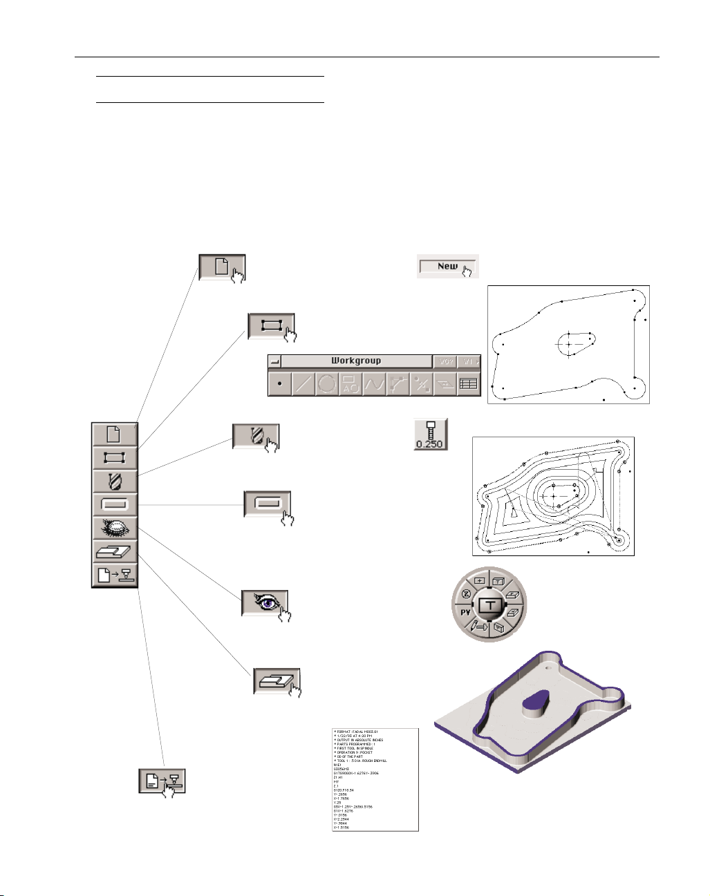
there are certain basic elements required to create a part. There must be geometry, a tool, and a toolpath (an operation) created before post processing. The Top Level Palette is organized in a logical
manner for building a part. A part does not have to be created in this order, it only serves as a guideline. Refer to the Tutorial in this manual for complete step-by-step instructions on part creation.
5
Create a new file.
Create part geometry.
Create a tool.
Create a toolpath.
Cut Part Render.
Post Process.
Change the view.
Page 8
◆
Level 0 Milling GFK-1702
CHAPTER 2
:
Interface
This system uses a Graphic User Interface (GUI). This simply means that pictures or symbols
are used in place of text whenever possible. This section of the manual describes the different interface objects and their uses.
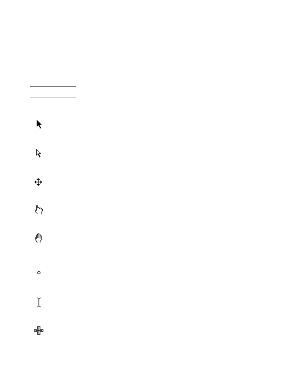
CURSORS
The cursor is the object moved with the mouse. Its appearance changes depending on its location. The different cursor appearances indicate different uses for the cursor.
Black Pointer : This cursor is used to select objects and geometry by clicking on them. Zoom
by dragging a rectangle around an area on the screen.
White Pointer : This cursor functions the same as the black pointer, except it is in multiple
selection mode. The white pointer appears when the Shift key is held down or when a geometry sub-palette is open. It allows more than one item to be selected at a time.
Mover Tool : This indicates that the cursor is placed on the edge of a palette or in a dialog’s
title bar. Move the palette or dialog by holding the mouse button down and dragging it to a
different location.
Pointing Finger : This indicates that the cursor is over a button. Push the button by clicking on
it.
Hand : This indicates that the cursor is over a draggable object such as a tile. Move the object
by clicking on it once and dragging it to the desired location. This cursor is also used to roll
the trackball.
Spot : The cursor changes to this while rolling the trackball.
I Beam : This indicates that the cursor is in a location where text input is accepted. It is a
flashing cursor.
Area Select : The cursor changes to this while doing a mouse drag or zooming in on an area.
6
Page 9
GFK-1702 Interface
◆
ACTIONS
There are a number of actions used throughout the system.
• Moving the cursor : The cursor is moved and positioned with the mouse.
• Click : A quick tap on any mouse button.
• Double-click : Two quick taps on the mouse button.
• Type : Using the keyboard.
• Drag : Position cursor, hold mouse button down, reposition cursor, release mouse button.
• Shift-click : Hold shift key down while clicking the mouse.
• Shift-double-click, Ctrl-click, Ctrl-double-click, etc. : Hold down stated key and
click (or double-click).
OBJECTS
Several interface objects are used throughout the system.
• Drawing Window
• Palettes
• Dialogs
• Tile Lists
• Menus
• Machining Markers
• Balloons/Prompts
• Wastecan
7
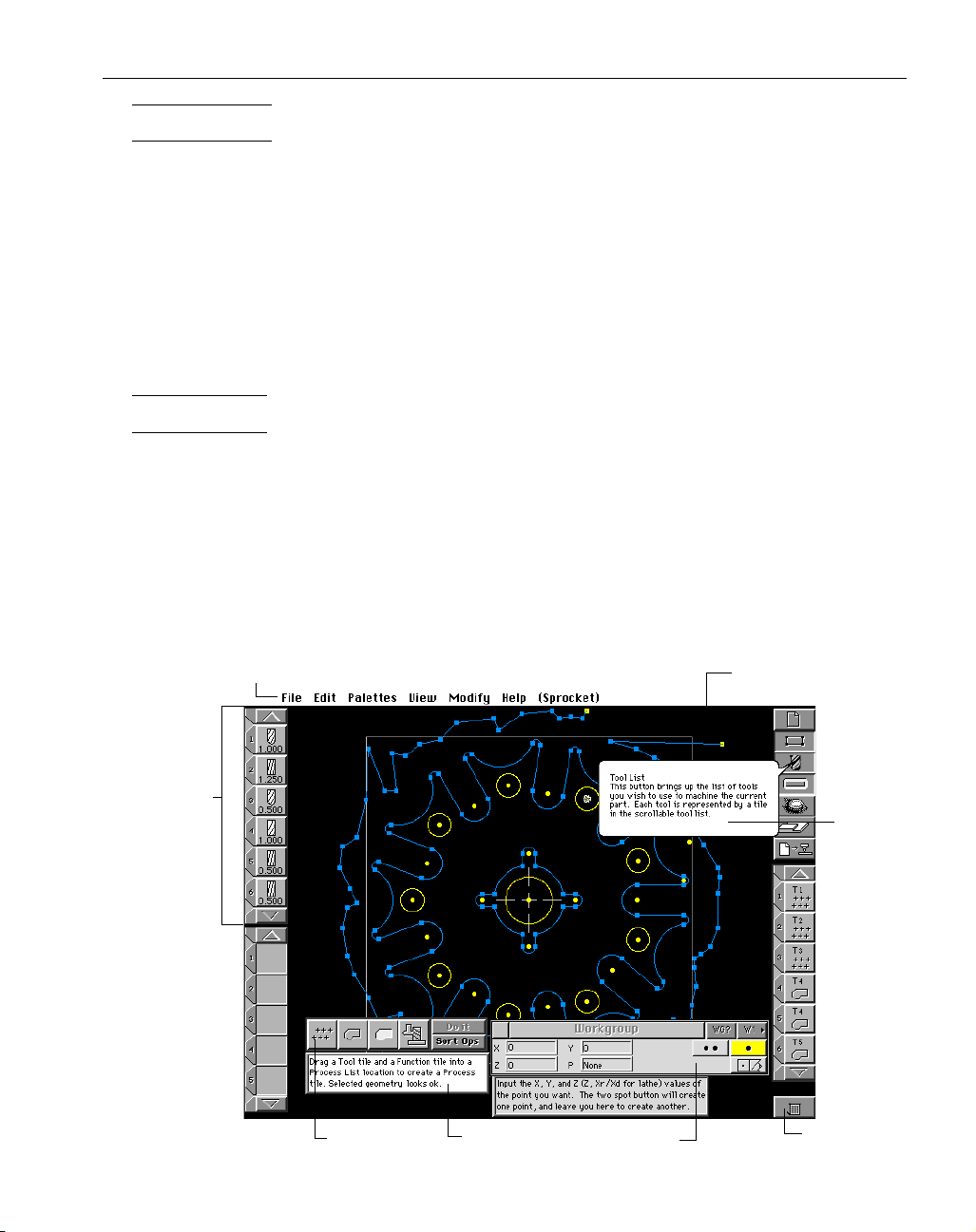
Menu Bar
Drawing
Window
Tile List
Palette
Prompt
Dialog
Balloon
Wastecan
Page 10
◆
Level 0 Milling GFK-1702
DRAWING WINDOW
The drawing window is the full size of the screen. All drawing of geometry, toolpaths, and rendered images appears in the drawing window. It is not moveable. All other interface objects appear
in front of the drawing window.
PALETTES
A palette is a collection of functions grouped together in a logical manner for the user. Some
palettes are moveable, others are not.
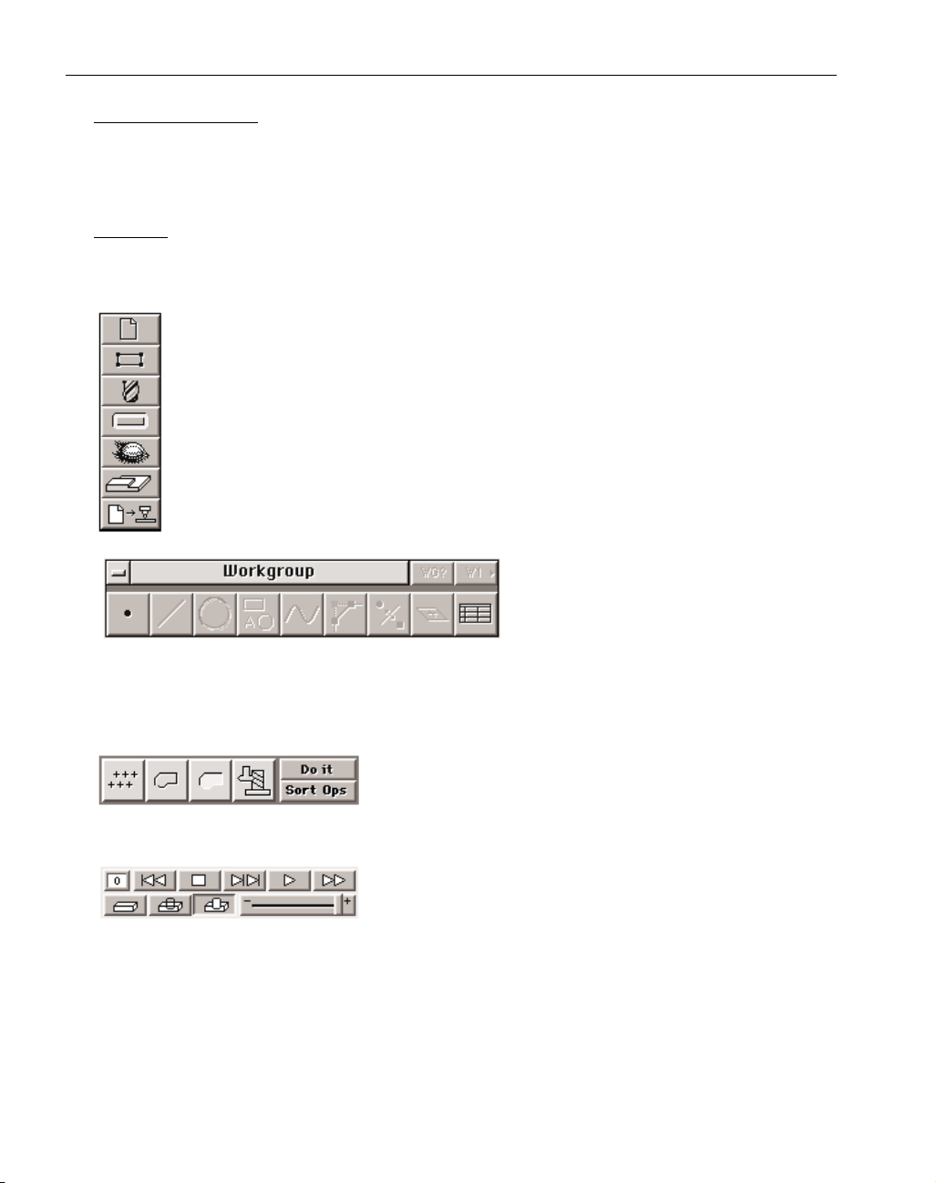
Top Level Palette : This palette is made up of buttons. These buttons can be either “on”
(depressed) or “off” (raised). Clicking once on a button turns it on and accesses the
appropriate dialog or palette. Another click will turn the button off and put any dialogs or
palettes away. The top level palette cannot be moved.
Geometry Creation Palette : This palette is also
made up of a group of buttons. However,
when one of the buttons is clicked on, it
does not stay depressed. Instead, it brings up
the point sub-palette or the Geometry Expert Spreadsheet. The Geometry Creation Palette can be
moved to any location on the screen. Move the palette by placing the cursor in the title bar of the
palette. When the cursor changes to the mover tool, hold the mouse button down and move the
palette. This action is called “dragging the edge”.
Machining Palette : This palette is made up of Function Tiles
and buttons. The four Function Tiles are moveable objects that
can be dragged to the Process List to create operations. The
Machining Palette can be moved to any location on the screen.
Cut Part Rendering Palette : This palette provides control over the
cut part rendering process. It allows the user to control rendering speed, the operations that will be rendered, and the way the
tool will be displayed. This is also a moveable palette.
8
Page 11
GFK-1702 Interface
◆
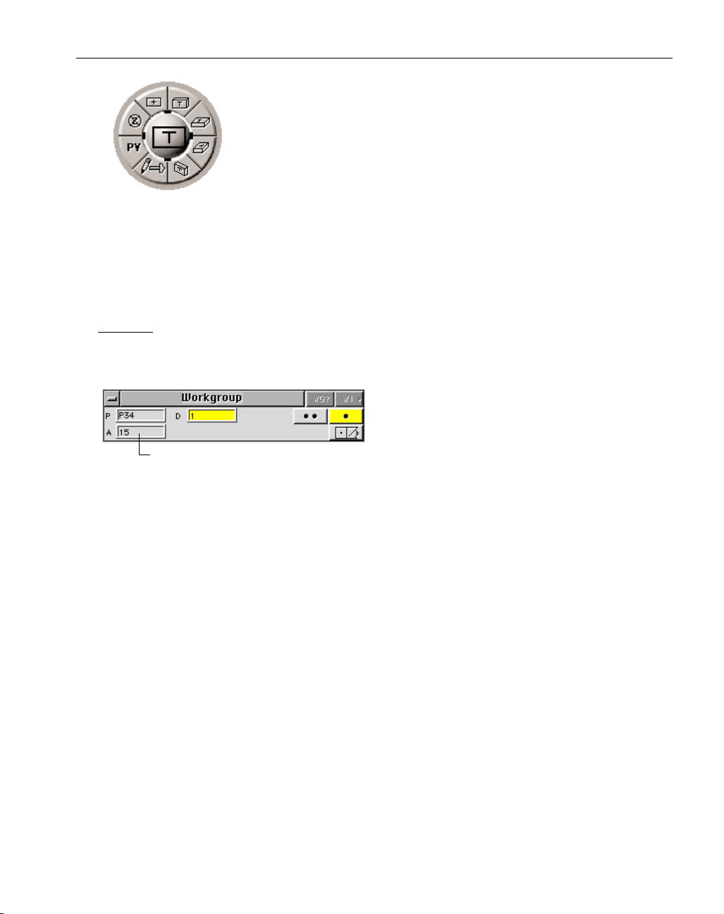
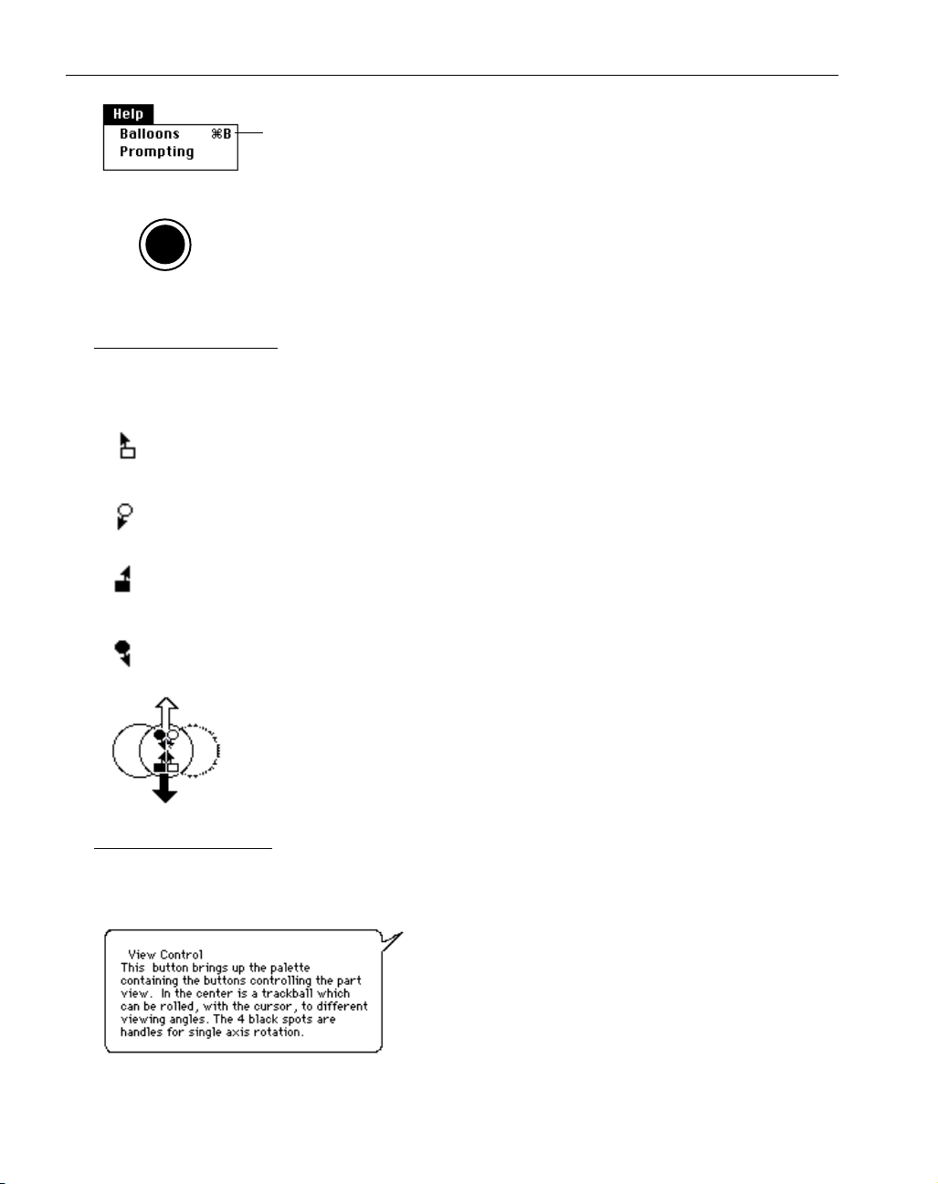
View Control Palette (Trackball) : The View Control Palette allows the user to
easily change the current view of the part. The buttons around the outside
provide standard view changes, redraws and unzooms. The center ball operates like a trackball and rolls to allow the part to be viewed from any orientation. When the cursor is placed over the ball, it changes into a hand, which
indicates that the ball can be rolled. Holding the mouse button down and
moving the mouse will roll the trackball. The black outlined box on the ball
represents the orientation of the part. The "T" identifies the top surface of the
part. The dimensions of the box do not change with the actual part size. X is the long axis. Once the
desired view is obtained, and the mouse button is released, the part is redrawn in the new view. The
ball has four small solid black rectangles around it, inside the ring of buttons (located at 12:00, 3:00,
6:00, 9:00). These are called ball "handles". Drag these handles for a single axis view change. The
trackball is a moveable palette, drag its edge to move it.
DIALOGS
Dialogs are used when information is required from the user. This information is conveyed
through text boxes, radio buttons, yes/no buttons, and pop-up menus.
Text Boxes : Items that require keyboard input
have a box next to them. If you click once in a
text box, a flashing text cursor will appear where
you clicked. Anything typed will begin at the
flashing text cursor. To move the text cursor, click
at the desired location. Double-clicking in a text box will select (highlight) everything in the text
box. Anything typed at this point will completely replace the current contents of the box. To select
only portions of the contents of the text box, click before or after the text to be edited, hold the
mouse button down and drag.
Moving from one text box to another can be accomplished by simply clicking in the desired
box, or hitting the Tab key. The Tab key moves the cursor from one box to another, and highlights
the entire contents of each box.
The contents of all text boxes can be cut, copied and pasted to and from the clipboard by
choosing items from the Edit Menu.
Math Input in a Text box : All number input boxes will accept the four standard math function symbols
(+ - x / ), as well as a number of special functions, (both * and x are used for multiplication). Hitting
the equal key or tab key on the keyboard will display the final value. Special math functions
include:
r = squareroot
s= sine
c= cosine
t= tangent
a= arctangent
m= convert from inch to millimeter (x 25.4)
i= convert from millimeter to inch (/ 25.4)
9
Text Box
Page 12
◆
Level 0 Milling GFK-1702
Angle values follow the standard Cartesian coordinate system, shown below. Negative values
are acceptable as input.
Radio buttons : Radio buttons come in groups. When one of the buttons in the group is
depressed (turned “on”), the other buttons in the group are “off.” The button that is
depressed displays a small red dot or “light” to indicate that it is “on.”
Yes/No buttons : Yes/no buttons come one per option. Depress the button for
yes, pop it up for no. The button that is depressed displays a small red dot or
“light” to indicate that it is “on.”
Pop-Up menus : Pop-up menus provide multiple choices. A
pop-up menu looks like a button, but has an arrow indicating that there are more choices available. The menu is accessed by depressing it and dragging the
cursor down to scroll through the list. When the desired item is highlighted, release the mouse button to select it.
Geometry Dialog : Geometry Dialogs are used
for input of specific geometric information
when creating points. These dialogs contain
options for creating single points or multiple
points.
10
(-270°)
90°
180°
0°
(-180°)
270°
(-90°)
Page 13
GFK-1702 Interface
◆
Geometry Expert Spreadsheet:
All part geometry is created using the
Geometry Expert Spreadsheet. The
feature type buttons on the far left are
contained in a pull out graphic menu.
All other geometric information is entered in the feature rows in the various cells of the spreadsheet.
This is a moveable dialog that can be positioned anywhere on the screen. For more information on
Geometry Expert, refer to the Geometry Creation Chapter.
Moveable dialogs : Some dialogs
may be moved around on the
screen. The area at the top of
the dialog is called the title
bar. The title bar shows the
name of the dialog. Drag the
title bar to move the dialog.
The small box in the upper left
corner of the window is the
close box. Clicking in this box
puts the dialog away. Doubleclicking on the title bar will
hide the dialog and leave only
the title bar. An additional
double-click will restore the
dialog. This is useful for conserving screen space. Most of
the dialogs in the system can
be shrunk to the title bar in
this manner.
11
Close box
Dialog Name Title Bar
Page 14
◆
Level 0 Milling GFK-1702
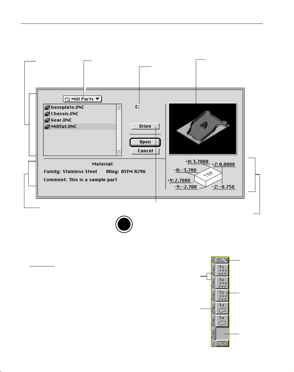
Open Dialog : The Open Dialog is used to locate, view, and open files. It comes up when Open is
selected from the File menu, or the Open button is depressed in the Document Control Dialog.
TILE LISTS
Tool Tiles, Process Tiles and Operation Tiles reside in
Tile Lists. Tile Lists have numbered positions or locations.
These positions can be empty or have a tile in them. Tiles may
be selected and dragged to any position in the list. To place a
tile between two tiles, drag the new tile to an insertion point
between two positions. Or, if you shift-double-click on an
insertion point, an empty location is created. Any tiles below
the insertion point will be moved down in the list. To move
tiles up in the list, shift-double-click on an empty position.
Depressing and holding down the scroll buttons located at the
top and bottom of the list, scroll the list in order to access tiles
higher or lower in the list. To scroll the list a “page” at a time,
12
Current Directory/
Folder: displays a list
of all available files in
the current directory
Material Information
and Part Comment
Pop-up menu to
access a higher level
directory, displays
current directory
Material Information
Button used to access the available drives and
disks contained on the system.
O
S
The name of the
current disk
On DOS, Windows NT and Windows
95 systems, it is the Drive button as
shown above. On Macintosh systems,
it is the Desktop button.
Part Preview:
displays the last
rendered image
of the part
Part Dimensions
Scroll
Button
Insertion
Point
Tile
Location
Number
Empty
Location
Page 15
GFK-1702 Interface
◆
hold down the scroll button and move the mouse in the direction of the arrow. The arrow will turn
red when scrolling a page at a time.
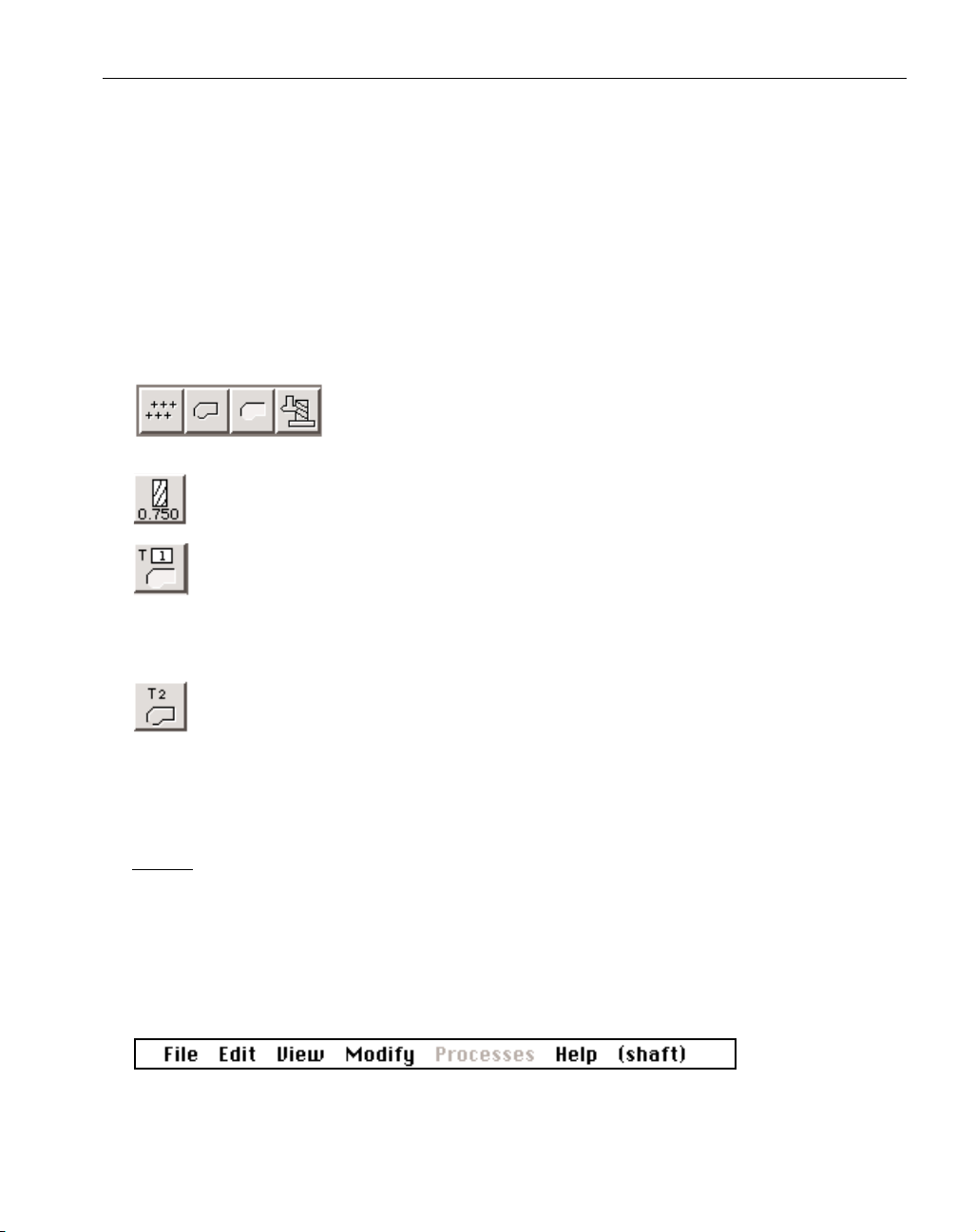
Tiles : The four different types of tiles are:
Function Tiles (Machining Palette)
Tool Tiles (Tool List)
Process Tiles (Process List)
Operation Tiles (Operation List)
Although the functionality of each type of tile is different, they have common features. All tiles
have a similar appearance, grey and square. Tiles can be dragged to tile lists.
Function Tiles: The four different types of functions are drilling, contouring,
pocketing, and thread milling. Function Tiles are dragged to a Process
List Location to create a Process Tile.
Tool Tiles : A Tool Tile is created by double-clicking on an empty Tool Tile Location. This
brings up a Tool Dialog. A Tool Tile displays a small tool symbol and the tool diameter.
Process Tiles : A Process Tile is created by dragging one Tool Tile and one Function Tile to a
Process List Location. A completed Process Tile displays the tool number with a box
around it, and a function symbol. When a Process Tile is created, a Process Dialog specific
to the selected machining function will appear on the screen. An incomplete Process Tile displays
either the tool number or the function symbol.
Operation Tiles : Operation Tiles are created from Process Tiles by clicking on the Do it but-
ton once the appropriate geometry has been selected for the cut shape. Each Operation Tile
represents one machining operation which contains the toolpath. An operation can either
drill or thread mill all selected points or circles, contour selected shapes, or pocket as much of the
selected geometry as possible without picking up the tool. An Operation Tile displays the tool number and function symbol.
MENUS
Menu Bar: The menu bar shown below is located at the top of the screen. It is available to the user at
all times. To access the menu bar, position the cursor over the menu bar title, hold the mouse button
down, drag the cursor until the desired item is highlighted, and release the mouse button. If a menu
item is grayed out it cannot be selected. Selecting geometry or some other appropriate item on the
screen may change the menu item so that it is available for selection. Some menu items are grayed
out because they are not supported by the Level 0 product. Refer to the Menus Appendix for a listing of these items.
13
Page 16
◆
Level 0 Milling GFK-1702
Keyboard shortcuts: Many menu items can be accessed by the keyboard. The letter next to the menu item indicates what key on
the keyboard will activate that item. Refer to the Shortcuts
Appendix for specific information on using keyboard shortcuts.
The symbol next to the letter will be different depending on the operating system
and the selection made in the Interface Preference.
MACHINING MARKERS
Machining Markers allow the user to specify the start and end feature and start and end point
of the cut shape, the cut direction, and the offset position of the tool. These markers appear on the
screen when geometry is selected for contouring processes.
Start Feature : The geometry feature (line or circle) on which the tool will start cutting.
Start Point : The point on the start feature where the tool will start cutting.
End Feature : The geometry feature on which the tool will stop cutting.
End Point : The point on the end feature where the tool will stop cutting.
Cutter Side and Direction : The circles represent where on the geometry the tool will
cut: on the outside of the geometry, on the inside of the geometry, or on the centerline. The arrows indicate which direction the tool will travel, making either a
climb or conventional cut. Click on the desired circle and direction arrow.
BALLOONS/PROMPTS
Balloons and prompts provide on-line reference information about the objects and functions in
the system.
Balloons : Balloons are turned on in the Help menu. A bal-
loon containing reference information will appear when
the cursor is placed over an object on the screen.
14
Keyboard
Shortcut
O
S
Page 17
GFK-1702 Interface
◆
Prompting : Prompting is also turned on in the Help menu.
Prompting extends the geometry and machining palettes to
include useful suggestions on how to use the software.
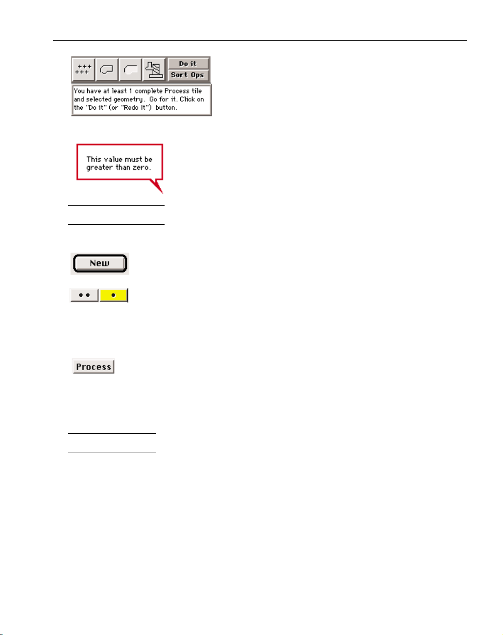
Error Balloons : Error balloons alert the user whenever an invalid value has
been entered. They are outlined in red and disappear when a valid entry is
made.
SHORTCUTS
Button Shortcuts : In some cases, buttons may be depressed by actions other than clicking on them.
When a button has a black outline around it, it can be depressed by hitting the enter
or return key.
Geometry dialogs give the user a choice of single or multiple point creation. To
create only one point, click on the single point button. To create more than one
point using the selected method, click on the multiple point button. One of the buttons will always
be highlighted. The highlighted button can be depressed by clicking on it, hitting the space bar, the
enter key, or the return key.
The Process button is found in some dialogs, primarily those found in the Modify
menu. It can be depressed by clicking on it, or by hitting the enter or return keys.
The system contains many other shortcuts that are described on platform specific Shortcuts
information cards and in the Shortcuts Appendix.
SELECTION
Three classes of objects may be selected in the system: text, geometry features and tiles. Text
and geometry can be cut, copied, and pasted to and from the clipboard within the same file by using
items in the Edit Menu. Selection techniques are described below.
15
Page 18

◆
Level 0 Milling GFK-1702
TEXT SELECTION
To select text:
• Click and drag the cursor over some text.
The text will become selected.
• Double-click in a text box.
All text in the box will become selected.
• Hit the tab key to move from text box to another.
All text in the box will become selected.
GEOMETRY SELECTION
To select a single geometry feature:
• Click on a feature.
The feature will become selected. If any other features were selected, they will
become deselected.
To select multiple geometry features:
• Shift-click on a feature.
If the feature was unselected, it will become selected and added to any other currently
selected features. If the feature was selected, it will become deselected and removed from
the currently selected group.
Holding down the shift key changes the cursor to multiple selection mode which
allows more than one geometry feature to be selected at a time.
To select an entire connected shape:
• Double-click on a feature of the shape.
All connected features will become selected.
To select certain types of geometry:
• Use the Select items found under the Edit menu.
All geometry that matches the selected type will become selected and added to the
currently selected group.
TILE SELECTION
To select a single tile:
• Click on a tile.
The tile will become selected. If any other tiles were selected, they will become deselected.
To select multiple tiles:
• Shift-click on a tile.
If the tile was unselected, it will become selected and added to any other currently
selected tiles. If the tile was selected, it will become deselected and removed from the currently selected group.
Holding down the shift key changes the cursor to multiple selection mode which
16
Page 19

GFK-1702 Interface
◆
allows more than one tile to be selected at a time.
COLORS
The system uses colors to graphically display different items drawn on the screen. The color
scheme for geometry, toolpaths and rendering is listed below.
GEOMETRY
Color Meaning
Yellow Unconnected Geometry
Light Blue Connected Geometry
TOOLPATHS
Color Meaning
Dark Blue Cut Shape; selected area of a shape to be machined
Solid Orange Feed Move in a Toolpath
Dashed Orange Rapid Move in a Toolpath
Dashed Gray Rapid Move used for positioning moves and tool changes
Solid Gray Approach Feed Move
RENDERING
Color Meaning
Blue Stock
Yellow Rendering of selected operations, and/or selected tools
Gray Rendering of unselected operations and/or unselected tools
Red Tool Interference
CLIPBOARD
The Clipboard is used as a temporary storage place for geometry and text. Using the Cut
option from the Edit menu will delete whatever items are selected and replace the contents of the
Clipboard with them. Using Copy will leave the selected items in their current location and replace
the contents of the Clipboard with a duplicate of them. Choosing Paste can do two things. If something is selected it will replace that selection with the contents of the Clipboard. If nothing is selected the contents of the Clipboard will be pasted in either the drawing window or in an active text box
depending on whether the Clipboard contains text or geometry. The Clipboard can only hold one
selection at a time. This means that it can hold either text or geometry, but not both. If text is
copied into a Clipboard holding geometry, the geometry in the Clipboard will be lost. The contents
of the clipboard will also be lost, when a file is closed, the software is quit out of, or the computer is
shutdown. Therefore, geometry can not be cut, copied or pasted between different part files because
the contents of the clipboard are deleted when the part file is closed.
17
Page 20
◆
Level 0 Milling GFK-1702
CHAPTER 3
:
Part Set-up
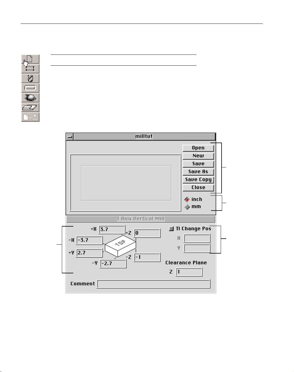
DOCUMENT CONTROL DIALOG
Clicking on the Document Control button will bring up the Document Control dialog.
This dialog is actually a combination of two linked dialogs. The top dialog contains file
management selections and also provides measurement type options.
The bottom dialog provides specific information about the part such as stock size,
clearance moves and tool change positioning.
The buttons used for file management, described below, are also available under the File menu.
Open Button : Clicking on the Open button will bring up the Open Dialog which allows the user to
select which file to open. If a file is currently open, it will be closed and the selected file will be
opened.
18
File
Management
Measurement
Type
Stock Size
Diagram
Tool Change
Position
Page 21
GFK-1702 Part Set-up
◆
New Button : This button will create a new file by opening a dialog and asking for a file name and a
location to save the new file. If there is a file open, it will be closed.
Save Button : If there have been any changes made while the file was open, this button will save the
changes.
Save As Button : This button will open a dialog asking for a file name and a location to save the current file. The changes made since the last Save command will be written into the new file. The original file will not be affected. The new file will become the current, open file.
Save a Copy Button : This button is very similar to the the Save As button. The system will create a
duplicate copy of the open file. The original file remains the current, open file. The name of the
duplicate file can be changed.
On DOS systems, if the original file name is less than 8 characters, the system will add
underscores to make the duplicate file's name 8 characters in length. If the original file's
name is 8 characters, the system will change the last character to an underscore to distinguish the original file and the copy. On Macintosh, Windows NT and Windows 95 systems, the
word “copy”will be added at the end of the file name to distinguish it from the original.
Close Button : This button closes the current file. If the file has not been saved before clicking on the
Close Button, a dialog will come up asking if the file should be saved.
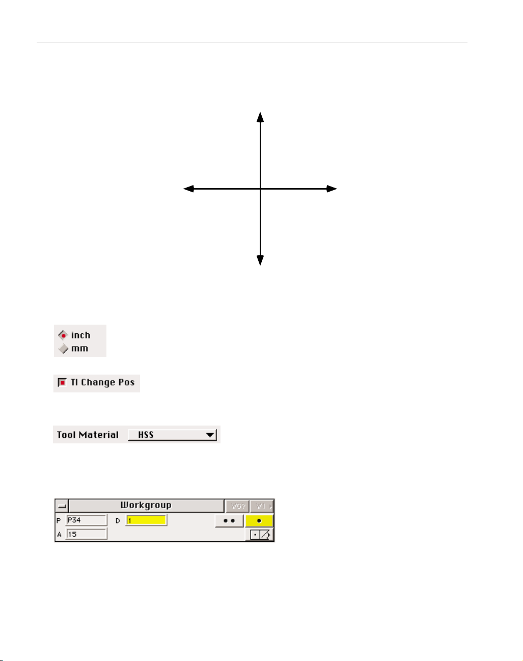
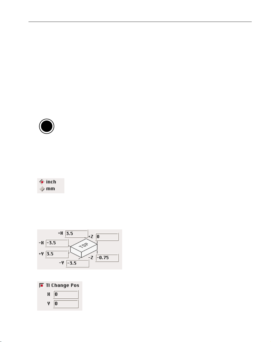
Measurement Type : These two radio buttons determine whether values input will be
based on an English or metric standard and entered in inches or millimeters. The
measurement type used by the post processor is determined by the post processor
itself. There are English and metric post processors. If an English post is used on a metric part, the
posted numbers will be converted from millimeters to inches. Likewise, metric posts will convert
values from inches to millimeters.
Stock Size Diagram : This section of the dialog is used to
specify the starting size of the part stock. The numbers
will be used to draw the stock outline and origin marker, and to draw the initial stock during the rendering
process. These values will not affect the programming
of the part, but it is recommended that they closely correspond to the actual stock being used.
Tl Change Pos : If Tool Change Position is on, the turret will be sent to the X
and Y dimensions specified before a tool change occurs. This option is
used on milling machines without automatic tool changers. It is also useful
when the table must be moved to avoid interference during a tool change
due to a tall part, fixtures or if a rotary table is being used.
19
O
S
Page 22

◆
Level 0 Milling GFK-1702
Clearance Plane : This position is used as a master Clearance Plane for the
part. This is the Z position the tool will rapid to and from during a tool
change. In addition, the tool will retract to this position between holes for
drilling operations, if the second Retract to Z option is selected in the
Drilling Process Dialog. This Clearance Plane is also used for multiple parts in the posted output.
Refer to the Machining and Post Processing Chapters for more information on clearance positioning.
Comment : Any text entered as a part comment will be shown in the part preview section of the Open
Dialog. In most cases, it will also appear in the posted output.
20
Page 23
GFK-1702 Geometry Creation
◆
21
CHAPTER 4
:
Geometry Creation
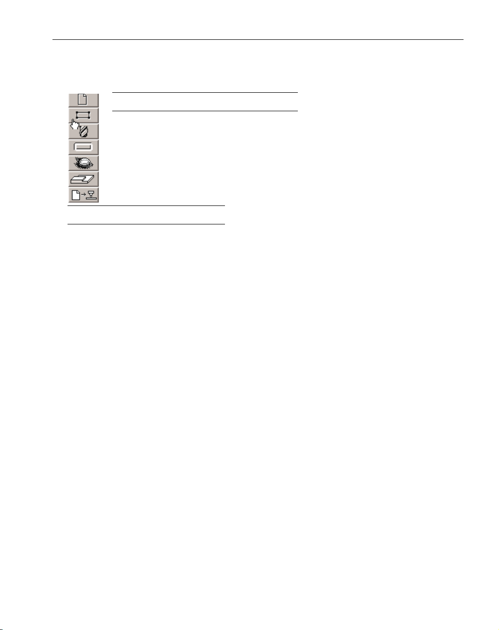
GEOMETRY OVERVIEW
Geometry must be created in order to machine a part. All part geometry is created
using the Geometry Expert spreadsheet and the Point sub-palette. Geometry Expert
combines the creation and connection of all geometry features in one powerful and easy
to use method. The Point sub-palette offers several methods for defining points. Once
created, geometry can be duplicated and modified using items in the Edit Menu and the
Modify Menu. There is an exercise at the end of this chapter that provides detailed
instructions on creating part geometry.
GEOMETRY EXPERT
Geometry Expert is a method of geometry creation which facilitates the fast creation of simple parts and the simplified creation of more complex parts, along with being very easy to learn
and use. Geometry Expert is designed to create a single, continuous, shape. It allows the user to
define, create and connect shape features while following along the path of the part.
Geometry Expert has a tabular format which operates much like a standard spreadsheet.
Features are defined by entering dimensions into the cells (text boxes) of the feature rows. Each
row creates a different feature. Features are defined in the same order as they are encountered
along the shape path.
Creating a shape using Geometry Expert is akin to “walking” around the path of the shape,
indicating such items as location, direction and the distance being traveled. While this is similar to
standard shape creation techniques, Geometry Expert goes one step further. It applies its inherent
knowledge of geometric principles and follows a logical course which allows for the creation of
complete, connected, geometrically correct shapes requiring the least amount of input from the
user.
Geometry Expert, as the name implies, provides the user with a built-in consultant on the
rules and principles of geometry. The creation of simple shapes, containing primarily horizontal
and vertical lines, such as shafts, is almost effortless using Geometry Expert. The default settings
and automatic angle toggling allow the user to create alternating, intersecting horizontal and vertical lines in the fastest manner possible. The user only needs to enter one value in order to define
the line. The creation of more complex shapes, containing multiple arcs and angled lines, is greatly simplified due to the fact that Geometry Expert constantly applies its built in logic and knowledge of geometry to guide the user through the process.
Finally, Geometry Expert is a very powerful editing tool. The associative capabilities of
Geometry Expert make editing any existing shape a very easy process. The system handles the
dimension changes while maintaining all the proper connections and relationships between pieces
of geometry (eg. intersections and tangencies). Feature dimensions can be adjusted by simply
changing the values in the spreadsheet. Geometry Expert handles all of the calculations and
adjustments to the other features that are affected by the changes. Geometry Expert frees the user
from needing to understand complex geometrical relationships and calculate feature dimensions.
Instead, the user can simply enter the specifications provided on the part blueprint and let
Geometry Expert do the rest.
Page 24
◆
Level 0 Milling GFK-1702
22
HOW GEOMETRY EXPERT WORKS
Geometry Expert is set up much like a standard spreadsheet. Feature specifications are
entered into cells which are contained in rows. Each row of the spreadsheet defines a feature.
Features are defined in the order that they appear along the path of the shape. When the
Geometry Expert spreadsheet is open on the screen the user can create fully connected shapes by
entering feature specifications in each of the rows. Because Geometry Expert creates connected
shapes, each feature is dependent on and aware of the preceding and following features.
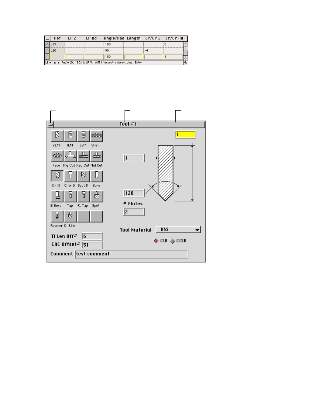
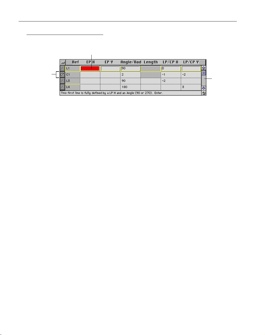
The feature row that is being worked on at any given time is referred to as the “current row”.
The current row has an upraised frame and is outlined in either yellow or black. When the current
row contains adequate information, it is outlined in yellow. The prompt at the bottom of the
spreadsheet, which gives the status of the current row, will indicate what will happen when the
row is entered.
The current row will be outlined in black if it does not contain enough information. The
prompt will indicate what additional information is needed to define the row. If the user attempts
to enter a row that does not contain enough information, an error balloon will come up, again indicating what other information is required. When the current feature row contains the appropriate
information, the row is entered into the spreadsheet by hitting the enter or return key. Entering a
new row moves the cursor down to the next row in the spreadsheet, which will now be the current
row. The enter and return keys only move the current row down in the spreadsheet if a new row is
being created. Otherwise, the arrow keys or the cursor must be used to maneuver through the
rows in the spreadsheet.
Each feature is drawn on the screen as soon as the spreadsheet contains the necessary information. Some features cannot be drawn until later features are defined. These are referred to as
“floating features” and are explained later in this section.
Creating part geometry with Geometry Expert is accomplished by walking along the path of
a shape, and defining features as they are encountered. In this way, all features are automatically
connected to the preceding and following features. Because of this methodology, sometimes it is
necessary to specify the correct direction of a feature, in addition to indicating its magnitude.
For arcs, the selected feature type indicates the direction, either clockwise or counter-clockwise. For lines, the angle value indicates the direction. For example, a horizontal line can either
be defined with an angle value of 0° or 180°; both will draw the same line, but in the opposite
direction. Specifying the correct line direction is only an issue if the previous or next feature is
going to be an arc. When that is the case, it is necessary to indicate to the system what direction
the line is moving. Again, checking the line direction should only be necessary when the line is
being connected to an arc.
Cell
Feature Row
Scroll Bar
Page 25
GFK-1702 Geometry Creation
◆
23
CREATING SHAPES USING GEOMETRY EXPERT
When creating a part using Geometry Expert, the first thing that must be decided is the starting feature and the direction to travel around the part, either clockwise or counter-clockwise.
When the spreadsheet is first opened, the first row will default to a line with an angle of 90°. The
information in this row will need to be added to and/or changed in order to define the first feature.
The prompts indicate what additional information can be entered to define the feature. As
soon as the first row contains enough information to fully define the feature, the frame of the row
will become yellow. When the frame is yellow, the prompting information tells the user how the
feature will be created. A yellow frame around the row indicates that the user can press enter
without getting an error message. Hitting enter or return will create the feature and start a new
row. The reference number of the feature that was created will be placed in the Ref cell in its row.
The new row’s feature type will default to a line, and the angle will default to either 0°/180°
or 90°/270°. The angle value of the line will automatically toggle between either 0°/180° or
90°/270°. Once again, the prompt will indicate what information can be added to further define
the line.
In this case, and many others, the frame of the row will be yellow even if the row does not
contain enough information to fully define the feature. This is because it is still possible to add
information in subsequent rows that will fully define the feature. At this point, information can be
added to or removed from the row to define the next feature of the shape as dimensioned on the
print. When the information is correct, the feature is created by hitting the enter or return key.
This process continues until the last feature of the shape is defined. When the last feature of
the shape is created it should intersect with the first feature of the shape. At this point the feature
must be connected using the Close Shape feature type.
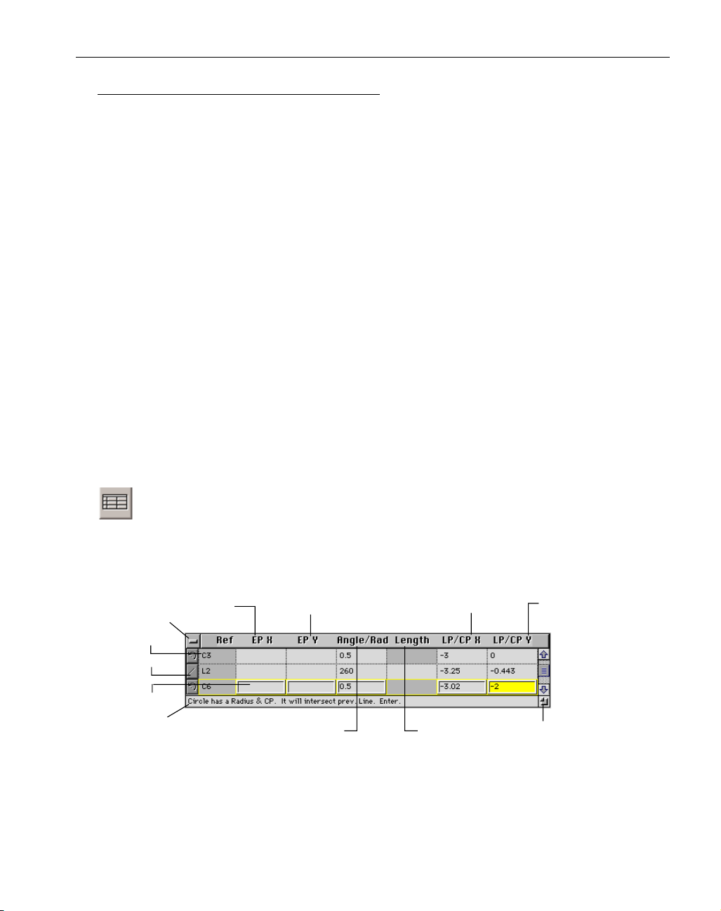
Geometry Expert button: The Geometry Expert button is located in the last position in the
Geometry Creation palette. Clicking on this button brings up the Geometry Expert
spreadsheet, shown below, which allows the user to create connected shapes by entering
feature dimensions in the rows of the spreadsheet.
Vertical (Y) Coordinate
of End Point
Angle of Line/
Radius of Circle
Close Box
Reference #
Feature Type
Current Row
Prompt
Horizontal (X) Coordinate
of Endpoint
Horizontal (X) Coordinate
of Line Point/Centerpoint
Length of Line
or Chamfer
Vertical (Y) Coordinate
of Line Point/Centerpoint
Size Box
Page 26
◆
Level 0 Milling GFK-1702
24
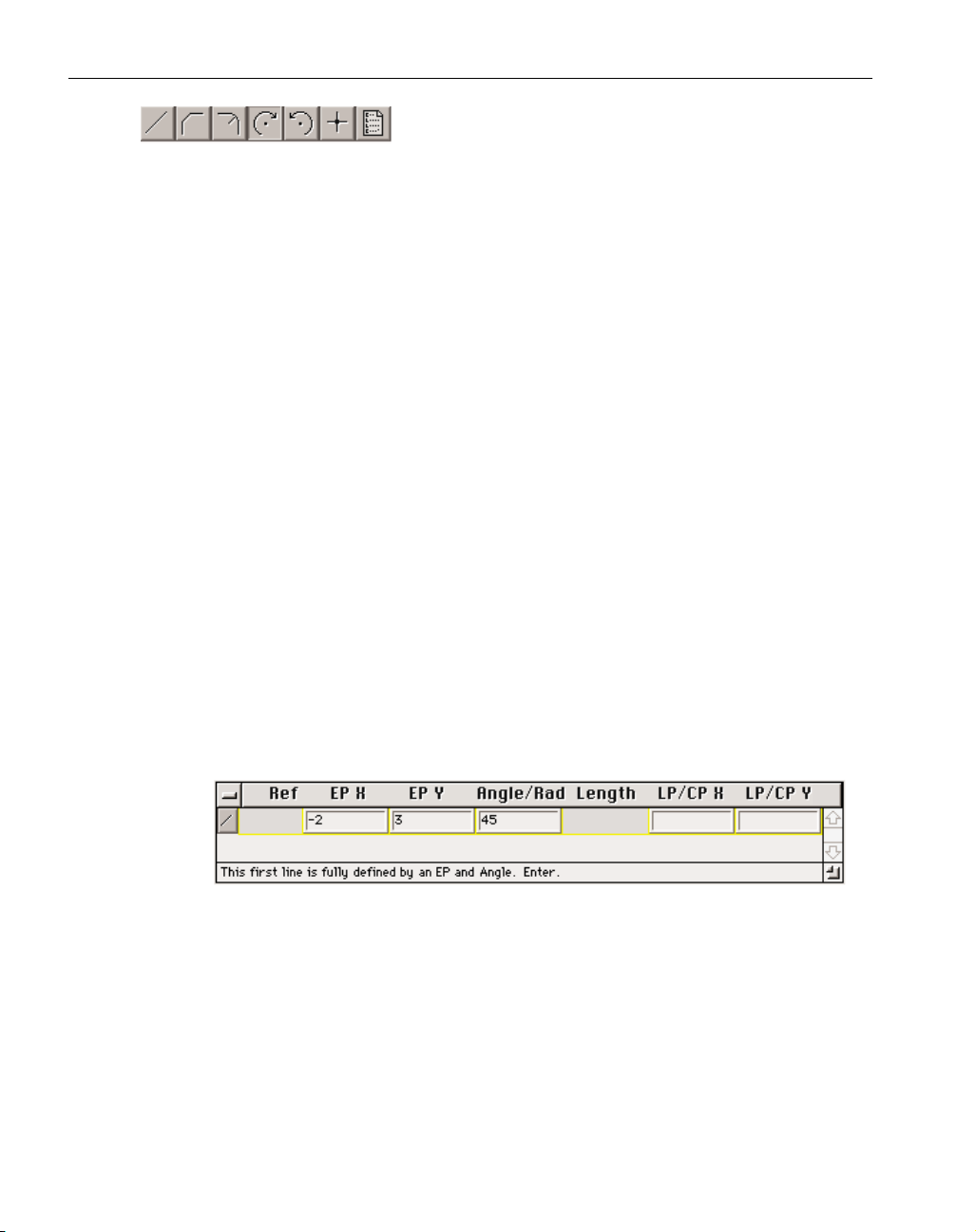
Feature Type: There are seven options available for the
feature type. They are (from left to right): line, chamfer,
fillet, clockwise arc, counter-clockwise arc, and close shape. Each row must have a
feature type selected. To select the feature type, click on the feature type button which will
access the possible selections. Drag the mouse to the desired feature so that the button
appears depressed, and let go of the mouse button. That feature will now appear as the
feature type for the row. In some cases, depending on the previous feature, some of the
feature type options may be grayed out to indicate they are not valid selections. Also,
depending on the feature type selected, some cells may be grayed out indicating that the
selected feature type does not require that dimension. The feature type can also be selected
using keyboard shortcuts. Refer to the Shortcuts information card or the Shortcuts Appendix
for information on keyboard shortcuts for Geometry Expert.
Reference #: Every feature that is created is assigned a reference number by the system. The
letter indicates what type of feature it is, L for line, C for circle, and the number indicates the
creation order. These reference numbers may change during the course of creating geometry,
but will not affect the shape.
EP X: The number entered in this cell is the horizontal or X coordinate of the endpoint of the
current feature. When a feature is defined with an endpoint, the system will draw the feature
and trim it at the specified endpoint. Endpoint specifications are required if the next feature
needs a start point in order to be correctly defined.
EP Y: The number entered in this cell is the Y or vertical coordinate of the endpoint of
the current feature.
EXAMPLE: The row shown below will create a 45° line with an endpoint drawn at
X -2, Y 3. The next feature that is defined in the spreadsheet will start at the end
point of this feature.
Angle/Rad: The number entered in this cell is dependent on the feature type selected.
If the feature type is a line, this number specifies the angle of the line. The angle value for a
line defaults to either 90°/270° or 0°/180° allowing for the creation of vertical or horizontal
lines, respectively. The system toggles between these angle values which makes the creation
of intersecting horizontal and vertical lines a very quick and easy process. The user can
change the default values by simply entering the new numbers in the cells. If the feature
type is a arc or fillet, this number specifies the radius.
Page 27
GFK-1702 Geometry Creation
◆
25
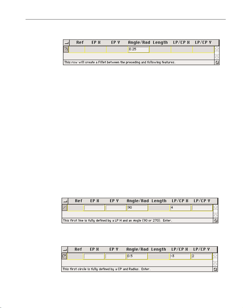
EXAMPLE: The row shown below will create a fillet between the previous and following feature with a radius of 0.25.
Length: The number entered in this cell is the length of the current feature. The length cell
is only active if the feature type is either a line or a chamfer.
LP/CP X: The number entered in this cell is dependent on the feature type selected. If the
feature type selected is a line, this number is the X or horizontal coordinate of a line point
(LP). A line point is any point that lies somewhere on the line. Line points are only
used to draw and calculate the line, they are not part of the shape. Line points are not drawn
on the screen. Geometry Expert defaults to the LP/CP cell so it is more efficient when
creating lines to use line points whenever possible in order to reduce the number of key
strokes necessary. If the feature type selected is a circle, this number is the horizontal
coordinate of the centerpoint of the circle.
LP/CP Y: The number entered in this cell is dependent on the feature type selected.
If the feature type selected is a line, this number is the Y or vertical coordinate of a line
point. If the feature type selected is a circle, this number is the horizontal coordinate of the
centerpoint of the circle.
EXAMPLE: The row shown below will create a 90° (vertical) line that goes through
the point at X 4. When defining either horizontal (0°/180°) or vertical (90°/270°)
lines, only one LP coordinate is required. Refer to the section on Half Points in this
chapter for more information.
EXAMPLE: The row shown below will create a circle with a radius of 0.5 and a
centerpoint at X -3, Y 2.
Page 28

◆
Level 0 Milling GFK-1702
26
Prompt: The information contained in the prompt indicates the status of the current row.
When a feature row is outlined in yellow, the prompt tells the user what specifications have
been entered for this feature and what will happen when the row is entered. If the feature row
is outlined in black indicating that more information is required, the prompt will tell the
user what additional information is required. The prompt also indicates if the system has automatically deleted a cell value because the feature row contained too much information that
overdefined the feature, this aspect of Geometry Expert is referred to as the “auto delete”
function which is explained in the Expert Aids section of this chapter.
Close box: Clicking in this box will close Geometry Expert. When Geometry Expert is closed,
all information is cleared out of the spreadsheet. When the Geometry Expert button is
depressed again, the spreadsheet will come up empty. In order to load or reload a shape into
the spreadsheet, double click on any feature of the shape while the spreadsheet is open
on the screen. All connected feature dimensions will be entered into the spreadsheet.
Size box : The size box allows the user to adjust the size of the Geometry Expert spreadsheet.
To adjust the size of the spreadsheet, click in the Size box and drag the window to the desired
size. The width cannot be changed, but the length can be adjusted.
Scroll Bar: The scroll bar and arrows allow the user to scroll through the rows contained in
the spreadsheet to make adjustments and check the values entered. This is useful if the spreadsheet needs to stay relatively small to fit on the screen, and/or if it contains many features.
EXPERT AIDS
There are several items built in to Geometry Expert that are designed to guide the user
through geometry creation. They include prompting, auto delete, and error balloons.
Prompting
The prompting information appears across the bottom of the Geometry Expert spreadsheet.
The prompt tells the user what actions are being taken by the system based on the information provided by the user. The user should be able to follow the prompts through the creation process to
get a good idea of what is happening.
Auto Delete
The auto delete function of Geometry Expert is intended to reduce errors resulting from fea-
tures being overdefined because too much information has been entered in the feature row.
Geometry Expert is designed so that the user need only enter the minimum amount of information
to define a feature. The system will automatically delete the first entry made in the feature row
when the feature is overdefined. Auto delete is necessary in order to facilitate the associative
capabilities of Geometry Expert. Note that the default values, such as the line angle, are considered the first entry rather than any information entered by the user. The prompt will indicate what
information is being deleted.
Page 29

GFK-1702 Geometry Creation
◆
27
Error Balloons
Geometry Expert also contains Error Balloons which appear on the screen whenever a problem occurs. The most common error messages appear when the system requires more information
for a feature being entered. For example, if a line needs another value for an end point, an Error
Balloon will come up indicating that a V or H value is needed to calculate the end point. The
Error Balloons and Prompting use the letters V and H, indicating Vertical and Horizontal.
Another common error message indicates that the feature being defined cannot intersect with
the previous feature. The non-intersecting feature can still be created, but the message indicates to
the user that the continuity of the shape has been broken and the subsequent features being created
will not connect to the existing shape.
ADDITIONAL INFORMATION
Defaults
When entering features in the Geometry Expert spreadsheet, the system contains defaults for
the feature type and line angle. The standard feature type default is a line. When Geometry
Expert defaults to a line, it also enters an angle value, either 90°/270° or 0°/180°, depending on
the angle of the last line entered. Sometimes a line is not a possible feature type option, in which
case the system defaults to an arc. This only occurs when the previous feature is a floating line.
Geometry Expert dimensions the line according the preceding and following feature specifications.
Floating features are not drawn on the screen until the system contains the necessary information.
Post Targeting
Despite all of its expertise, Geometry Expert can’t always know the correct intersection point
to use for a connector. When there are two or more, equally valid points of intersection, the system will draw both points. This is referred to as post targeting. When post targeting is required, a
dialog will come up that asks the user to select the appropriate point and click on the OK button.
Once the user has selected the desired intersection point, Geometry Expert will make the appropriate connection and continue along in the spreadsheet defining and connecting features.
The Edit menu contains an item that will change the intersection point selected in a post targeting dialog to the other possible point of intersection. The menu item toggles between Use
Intersection #1 and Use Intersection #2, depending on the point selected and where it lies along
the path of the shape. This option will be an active item when a feature that required post targeting is selected on the screen.
Half Points
In certain cases, only one coordinate, either the horizontal or vertical, is required to define
the feature. This is referred to as a half point case. Half points are valid when Geometry Expert is
able to calculate the other half of the coordinate value from information contained in the spreadsheet. (Either preceding or following features.)
When a valid half point is entered, the row will be highlighted in yellow, allowing the user to
enter the feature row. If the half point entered is not valid, the row will be highlighted in black
and the prompt will indicate what additional information is necessary to enter the row. If an
incomplete row is entered, an error ballon will come up indicating what additional information is
required. There are three cases where half points are valid. They are listed and explained below.
Page 30

◆
Level 0 Milling GFK-1702
28
Half Line Point: A half line point is valid only when creating either a horizontal line (angle
value = 0° or 180°) or vertical line (angle value = 90° or 270°). If creating a horizontal line, a
V coordinate must be given for a valid half line point. If creating a vertical line, an H coordinate must be given for a valid half line point. Line points are not part of the shape, but are
only used to calculate the position of the line.
Half End Point: A half end point is only valid if the line is otherwise completely defined.
Given either the vertical or horizontal coordinate of the end point along with the other information that defines the line, the system can calculate the other half of the end point. If a half end
point is used in the case of 0°/180° or 90°/270° lines, the half end point will function like a
half line point, in that an end point will not be drawn, although the correct line will be created.
Half Center Point: A half center point is valid when a circle has a radius value and is tangent to
the preceding feature. (There must be a preceding feature.) Given the radius and the vertical
or horizontal component of the centerpoint, the system can calculate the other half of the
centerpoint by the assumed tangencies.
Floating Features
Floating features are features whose defining row does not contain all of the information necessary to draw the feature. Floating feature rows are different from incomplete feature rows. With
floating feature rows, the information contained in the current feature row and the preceding rows
is inadequate to completely define the feature and draw it. However, subsequent features, defined
in following rows, could provide the necessary information to define the floating feature. Floating
feature rows are outlined in yellow and can be entered.
Incomplete feature rows do not contain enough information to create the feature, and no
amount of information entered in following rows will make the feature definable. Incomplete feature rows are outlined in black and cannot be entered without getting error messages.
Again, the row outline and the prompting information will indicate if the feature row can be
entered, and if it is, how the floating feature will be incorporated into the shape after later features
have been defined.
Inserting and Deleting Rows
The Edit menu contains options for inserting and deleting rows in the spreadsheet. When
inserting rows in the spreadsheet, the system will create a new row above the current row. To
insert a row, select the row beneath the row to be inserted. Then, select the Insert row option in
the Edit menu. When an inserted row is entered, the system will recalculate the shape and attempt
to incorporate the new feature into the existing shape, if possible.
To delete a row, simply select the row to be removed, and choose the Delete Row option in
the Edit menu. When rows are deleted, Geometry Expert will recalculate the shape, and attempt
to keep it continuous and connected. If that is not possible, error balloons will appear indicating
that features do not intersect and the shape cannot be connected.
Arcs vs. Fillets
Arcs with only a radius value and fillets appear to be very similar at first glance, but actually
use two completely different methods for calculating the circles. A fillet takes a sharp point produced by an intersection between two other features and changes it into a radius. It is created after
the intersection between the two features is completed. Because of this, it is dependent on the
intersection of the other two features to exist. This means that the system cannot use the fillet to
Page 31

GFK-1702 Geometry Creation
◆
29
calculate features that follow it in the spreadsheet. As the prompts indicate, Geometry Expert
completely ignores fillets (and chamfers) when calculating what information is necessary to define
features. When the prompt displays information about the interaction between the current feature
and the previous feature, fillets will be ignored.
An arc with only a radius value is created tangent to two other features. These two features
do not have to intersect. The arc is treated as an actual feature and can be used when calculating
other features of the shape.
This is particularly important when dealing with floating lines (lines with limited information) that have specific tangency requirements. Geometry Expert assumes that floating lines are
going to be made tangent to the preceding feature. In most cases this is adequate, but sometimes a
floating line is supposed to intersect the previous circle and be tangent to the next circle. This is
called a "forward" tangency.
In the case of forward tangencies, if there is a radius between the previous circle and the
floating line, then an arc, rather than a fillet, must be used in order to allow for the necessary tangency calculation. The line will be made tangent to both the arc used as a fillet and the next arc.
A fillet cannot be used in this case because the fillet will be ignored by the system until the intersection is completed, and the correct intersection cannot be created without the arc. If there is no
fillet, an arc with a radius of zero will need to be created. This will allow the system to create the
line tangent to the following circle, while creating a sharp point at the intersection of the previous
feature.
POINT CREATION
Points are used as positioning information for drilling and thread milling operations. They are
drawn as yellow circles. There are a variety of methods available to create points. Each is
described below.
Point button: Clicking on this button brings up the Point sub-palette, shown below, which
consists of a group of buttons containing the construction tools for creating points.
Point sub-palette: This sub-palette contains buttons which allow the user to
create points in 3D space in a variety
of ways. When each is depressed,
a geometry dialog appears on the screen. Geometry dialogs are used for input of specific
geometric (numerical) information in the creation of points.
XYZ button: Create a point by typing in the X, Y and Z coordinate values for
the point.
Polar Point button: Create a point at some angle and distance from an existing
point.
Page 32

◆
Level 0 Milling GFK-1702
30
Bolt Circle Point button: Create a circular pattern of points by entering the
appropriate information in the dialog shown below.
Matrix Point button: Create a parallelogram pattern of points by entering the
required information in the dialog shown below.
Centerpoint button: Create a point at the center of an existing circle.
Mouse Point button: Create a point each place the mouse button is clicked
based on user-defined grid spacing.
Return button: This button appears at the far right end of the point subpalette, and returns the user to the Geometry Creation palette. It can also be
activated by hitting the escape key on the keyboard.
X Coordinate of
Pattern Centerpoint
Y Coordinate of
Pattern Centerpoint
Radius of
Circle Pattern
Z Depth
of Points
Creation Order Direction
(CCW or CW)
Angle to 1st Point
# of Points
in Pattern
Side 1
Change in X
Side 1
Change in Y
# of points
in Side 1
Y Coordinate
of 1st Point
X Coordinate
of 1st point
Side 2
Change in Y
Side 2
Change in X
Z Depth
of Points
# of Points
in Side 2
Page 33

GFK-1702 Geometry Creation
◆
31
EDIT MENU
The Edit menu contains items that allow the user to adjust and
select items contained in the file. Each item found in this menu is
described below in the order it is encountered in the menu.
Undo: This item will undo the last action performed. Some actions
cannot be undone. When Undo is grayed out in the menu, the previous action cannot be undone.
The Cut, Copy and Paste functions allow selected items, geometry or text, to be duplicated and/or moved in a file. This is accomplished using the clipboard, which is a temporary storage place contained in the system. These functions only work within the currently
open file because the contents of the clipboard are erased when a file
is closed. Refer to the Clipboard section in the Interface Chapter for
additional information.
Cut: This function will delete any selected items, and copy these
items to the clipboard. The item(s) can then be placed in the same
file using the Paste function.
Copy: This function will make a duplicate of the selected items and copy it to the clipboard. The
item(s) can then be pasted in the same file.
Paste: This function will place the contents of the clipboard in either the drawing window, if the
clipboard contains geometry, or an active text box, if the clipboard contains text. If another item is
selected when pasting, that item will be deleted and replaced by the contents of the clipboard.
Select All: This function will select all of the geometry contained in the current workgroup.
Deselect All: This item will deselect any geometry currently selected.
Insert Row: This item will insert a blank row in the spreadsheet above the current row selected.
When an inserted row contains the necessary information and is entered, the system will recalculate
the shape and attempt to incorporate the inserted feature into the existing shape, if possible.
Delete Row: This item will deselect the selected row from the spreadsheet. As soon as the row is
deleted, the system will adjust the remaining shape to maintain the appropriate connections, if possible.
Use Intersection #1 (#2): This item will toggle between Use Intersection #1 and Use Intersection #2
in the menu. This option enables the user to select different intersections between concurrent features in the spreadsheet. This option is available when the feature defined by the current row intersects the feature defined by the following row in two places. This item will change the point of
intersection, selected in a previous post targeting dialog, to the other possible choice.
Page 34

◆
Level 0 Milling GFK-1702
32
Reverse All Rows: When this item is selected it will reverse the order of the rows in the spread sheet
which will change the direction of the shape as it is loaded in Geometry Expert. This is useful when
loading a shape that was imported or created using the Free Form CAD tools. When a shape that
was not created using Geometry Expert is loaded into the spreadsheet, the system decides whether
to go in a clockwise or counter-clockwise direction when placing the features into the spreadsheet.
The direction has the potential to affect the angle values of lines and the direction of arcs of the
shape. There are times when the system will load the shape in the opposite direction than desired.
When the shape has been loaded into the spreadsheet, select the Reverse all rows item to reverse the
order of features. This item is only available when the spreadsheet contains feature rows.
NOTE: The Select, Deselect and Redo All Ops items are only available with the Level 1 version of
this software.
MODIFY MENU
The Modify menu contains items that give the user additional
methods for creating, positioning and duplicating geometry. The
Modify Menu is grayed out when the Geometry Expert spreadsheet is
open. To use the items in the menu, close the spreadsheet and it will
become available. The Operation Data item is explained in the
Machining Chapter.
All of the items under this menu, except Operation Data and
Move Part Origin, require geometry to be highlighted before their
function can be performed. The Operation Data menu item requires
an operation to be highlighted.
Each item found in this menu is described below in the order it is
found in the menu.
Duplicate: This selection copies the selected geometry, in the same location. After this is done, the next appropriate step is to move the duplicated geometry to another location, possibly using another item under
this menu.
Duplicate And: This selection will perform the individual functions Duplicate
and then Force Depth, Mirror, 2d Rotate, Scale or Translate at one time.
First, the selected geometry will be duplicated. Then, depending on the
option selected, the selected geometry is moved to one or more new locations based on the number typed in the times box. The specific button choic-
es work the same as the items detailed below.
Page 35

GFK-1702 Geometry Creation
◆
33
Set Default: Selecting a point and then choosing Set Default will cause the selected points X, Y and
Z locations to appear as the default values in any other appropriate Modify menu dialog. This item
is useful if a drawn point is used to mirror around, rotate around, etc.
Force Depth: This selection sets the Z value of all selected geometry to the Z value
entered.
Mirror: This selection will move the selected geometry to the other side
of the axis or axes specified, around an axis point entered in the text
boxes. Clicking on the Process button will perform the mirroring func-
tion. This dialog can remain on the screen for further use while other
functions are performed.
2D Rotate: This selection will revolve or rotate the selected geometry
around the point specified in the X andY boxes. The selected feature will
be rotated by the amount specified in the Angle box, in either a CW
(clockwise) or CCW (counter-clockwise) direction depending on the
selection made. Clicking on the Process button will perform the rotating
function. This dialog can remain on the screen for further use while
other functions are performed.
Scale: This selection will change the size of the selected geometry by the
amount specified. The value typed in the Amount box is a ratio of 1, 1
being full size. The inches to mm or mm to inches buttons will change
the geometry to the opposite numerical type. If the Include Z option is
turned on, the Z values of the selected geometry will be included in the
scaling process. Include Z will not have an affect if the selected geometry is at Z0. Clicking on the Process button will perform the scaling
function. This dialog can remain on the screen for further use while
other functions are performed.
Page 36

◆
Level 0 Milling GFK-1702
34
Translate: This selection will move the selected geometry by the offset
amount. Clicking on the Process button will perform the translating
function. This dialog can remain on the screen for further use while
other functions are performed.
Reverse Arc: A circle can be fully connected either using the less than 180° arc or with the greater
than 180° arc. The system automatically selects the less than 180°arc as the fully connected feature.
If the other arc is needed, select the connected arc and the Reverse Arc item. In other words, select-
ing Reverse Arc will cause the system to use the other side of the connected arc.
Move Part Origin: This selection will move ALL the geometry incrementally by
the values typed in the X, Y and Z boxes. The current location of X0, Y0, Z0
will change incrementally by the values in this dialog and a new X0, Y0, Z0
will be established. Clicking on the Process button will move the origin. This
dialog can remain on the screen for further use while other functions are performed.
Operation Data: This item is used with machining operations and is explained in the Machining
Chapter.
NOTE: The Sort, Change CS XYZ and Change CS HVD items are only available with the Level 1 version of this software.
WORKGROUP SUMMARY
Selecting Workgroup Summary from the part menu (title of this
menu will be the name of the part) will bring up the Workgroup
Summary dialog which provides information in spreadsheet form
about all features and points contained in the current workgroup.
When the Workgroup summary is open it can be printed by select-
ing the Workgroup Summary item from the Print submenu under the File menu.
Page 37

GFK-1702 Geometry Creation
◆
35
PRINTING THE PART GEOMETRY
After the part geometry has been created, it can be printed. Geometry can either be printed in
black and white or color. When the desired geometry is on the screen, choose Drawing from the
Print sub-menu under the File menu. To adjust the way the image will print, choose Printing from
the Preferences sub-menu in the File menu. The Printing Preferences dialog, shown below, allows
the user to specify how the software will handle the background color. If the printer being used is a
black and white printer, choose the Black on White option to ensure that all portions of geometry,
including those that are a light color, can be seen in the print.
For specific information regarding printing on the different operating systems, refer to the
Printing Appendix found at the end of this manual.
O
S
Page 38

◆
Level 0 Milling GFK-1702
36
GEOMETRY EXERCISE
In this exercise, we will create a simple shape composed of arcs and
lines. Geometry Expert takes care of the connecting intersecting features. The part print for this exercise is provided at the end of this
section.
• Launch the system.
The Operating Systems Appendix provides specific instructions on
launching the system.
• Click on the Document Control button in the Top Level palette.
When the Document Control button is depressed, the Document
Control dialog will appear on the screen. This dialog contains file
management options, as well as general information about the part,
stock measurements and clearance positioning.
• Click on the New button.
Page 39

GFK-1702 Geometry Creation
◆
37
The Save dialog, shown below, will appear on the screen.
• Type “exercise” in the New File Name box.
• Click on the Save button.
When you save files you want to make sure that you are saving them
in the appropriate location on your hard drive. You may need to
change drives and/or directories or folders in order to save the file in
the desired place.
To change drives, DOS and Windows users click on the
Drive button, Macintosh users on the Desktop button, in
the Save dialog shown above. To change directories or
folders, double click on the name of the directory/folder in the current list. The pop-up menu above the list displays the name of the
current directory/folder and allows you to access lower level directories/folders.
• Select mm for the measurement type.
• Enter the stock values shown below.
The stock values entered are slightly larger than the part dimensions
so that we can see all of the geometry within the stock outline.
• Type “This is a sample part” in the Comment text box.
O
S
Page 40

◆
Level 0 Milling GFK-1702
38
If a comment is entered in this text box, it will appear in the Open
dialog when this part is selected.
Because we are only creating part geometry in this exercise, the
clearance and tool change positioning information does not matter.
When all the information about the part has been entered, close this
dialog. The information contained in it may be changed at any time,
simply by clicking on the Document Control button and entering the
new information.
• Close the Document Control dialog by clicking twice in the close box in the
upper left hand corner of the dialog.
A stock outline is drawn with a “+” that signifies the origin of the
part which is located at X0, Y0. Your screen should now look like
the picture shown below.
Another way to close this dialog is to click on the
Document Control button in the Top Level palette again,
so that it “pops up.”
Page 41

GFK-1702 Geometry Creation
◆
39
• Click on the Geometry Creation button in the Top Level palette.
The Geometry Creation palette will come up on the screen.
• Click on the Geometry Expert button in the Geometry Creation palette.
When this button is depressed, the Geometry Expert spreadsheet will
appear on the screen. It may be necessary to move the spreadsheet
and size it in order to get a better view of the part. To change the
size of the spreadsheet, use the size box and drag the spreadsheet to
the desired length.
The spreadsheet is a moveable object, which means it can
be placed anywhere on the screen. To move the spreadsheet, place the cursor on the title bar, so that the cursor
changes to the mover tool. Then, while holding down the
mouse button, drag the dotted outline to a different location and let go of the mouse button.
Page 42

◆
Level 0 Milling GFK-1702
40
Feature dimensions will be entered in the rows of the spreadsheet to
form a shape. The arrow shown below on the left indicates the current row of the spreadsheet. The current row signifies the feature
row being worked on. The prompt information always refers to the
current row. The current row has an upraised frame and is highlighted in either yellow or black, depending on its status. When the
spreadsheet first comes up, the first row, which is the current row, is
highlighted in black because the row needs more information in
order to define the feature.
Notice that when the spreadsheet comes up, the feature type selected
is a line, and the angle value is 90°. As we are going through the
exercises, be sure to watch the prompt at the bottom of the spreadsheet. It provides useful information pertaining to the status of the
current row.
We will begin creating the shape by choosing a feature and “walking” around the part in a counter-clockwise direction creating the
shape feature by feature. The feature we will start with is the vertical line at Y0.
• Enter the line point value shown below.
When defining either horizontal or vertical lines, it is only necessary
to enter a half point for the line point.
When only one coordinate value is entered, it is referred
to as a half point. In certain cases, the system only
needs either a horizontal (H) or vertical (V) coordinate
value in order to define the feature. For more information on half points, refer to the Geometry Expert section
in this chapter.
Current
Row
Current
Row
Page 43

GFK-1702 Geometry Creation
◆
41
Once the line point is entered, the current row becomes highlighted
in yellow indicating that it now contains enough information to
define the feature. When the current row is highlighted in yellow,
the prompting information states what will happen when the user hits
enter.
• Hit the enter or return key.
When creating a new row, hitting the enter or return key will create
the feature and move the current row of the spreadsheet down one.
If you are working on existing rows, entering the row will not move
the current row down in the spreadsheet, it will only make the necessary changes. The arrow keys or the cursor must be used to move up
and down within existing rows of the spreadsheet.
Your screen should look like the picture shown below.
When the row is entered, the line is drawn on the screen and the current row of the spreadsheet moves down one. The second feature
row has a line selected for the feature type and the angle is 180°.
The system angle defaults toggle between 0°/180° and 90°/270°, and
places the cursor in the appropriate cell.
• Click on the Feature Type button and drag the cursor to the Fillet feature
type (3rd button) so that it becomes depressed. Release the mouse button.
The feature type can also be selected using keyboard shortcuts.
Refer to the Shortcuts Appendix for specific information on using the
keyboard shortcuts.
Page 44

◆
Level 0 Milling GFK-1702
42
• Enter the radius value shown below.
Only a radius value is required when creating fillets. Therefore, the
other cells in the row are grayed out.
Notice the prompt. “This row will create a fillet between the preced-
ing and following features.” Fillets and chamfers are entered in the
spreadsheet between the two features they connect with. Fillets and
chamfers can only be created between two intersecting features at
their point of intersection. Refer to the Geometry Expert section in
the Geometry Creation Chapter for more information on arcs and fillets.
• Hit the enter or return key.
Nothing is drawn on the screen, although the fillet is now entered in
the spreadsheet. Fillets and chamfers are not drawn on the screen
until the two features they exist between are fully connected.
• Enter the line point value shown below.
Notice that the line angle toggled to 180°.
• Hit the enter or return key.
Current
Row
Current
Row
Page 45

GFK-1702 Geometry Creation
◆
43
Your screen should look like the picture shown below.
The two lines are connected. Connected features have a blue square
(connector point) drawn at their intersection or tangency. When a
feature has two connector points, it becomes blue and trims.
Geometry Expert automatically connects features as they are drawn.
If two concurrent features do not have a point of intersection or tangency, the system produces an error message indicating that the previous feature can not intersect with the current feature. When both of
these lines become fully connected (have two connector points), the
fillet that was created at their intersection will be drawn on the
screen.
• Select the Fillet feature type and enter the radius value shown below.
• Hit the enter or return key.
• Enter the line point value shown below.
• Hit the enter or return key.
Current
Row
Current
Row
Page 46

◆
Level 0 Milling GFK-1702
44
Your screen should look like the picture shown below.
Notice the horizontal line turns blue and trims because it now has
two connector points.
• Select the Fillet feature type and enter the radius value shown below.
• Hit the enter or return key.
Again there is no change on the screen, but the fillets will be drawn
when the lines become trimmed and connected. If the Geometry
Expert spreadsheet is closed before fillets and chamfers have been
drawn on the screen, they will be lost. Any rows in the spreadsheet
that contain information for features that have not been created (eg.
fillets, chamfers, floating features) will not be maintained when the
spreadsheet is closed.
• Enter the end point coordinates shown below.
Current
Row
Current
Row
Page 47

GFK-1702 Geometry Creation
◆
45
It is necessary to enter an end point for this line because the following arc is not tangent to this line. Anytime an arc is not tangent to
the preceding feature, it needs a start point. A start point is specified
by entering an endpoint for the preceding feature.
• Hit the enter or return key.
Your screen should look like the picture shown below.
Two of the fillets have now been drawn, and the line defined with an
endpoint is trimmed. Once a feature has been drawn on the screen, a
reference number is assigned and entered in the Ref cell of the
spreadsheet.
• Select the Clockwise Arc feature type and enter the radius value shown
below.
Notice the prompting information at the bottom of the spreadsheet.
It states that the circle will start at the last row’s end point and be
tangent to the next feature, therefore only a radius value needs to be
Current
Row
The tab key or the arrow keys move the cursor from one
cell to another within any row. The mouse can also be
used to change cells by clicking in the desired cell.
Page 48
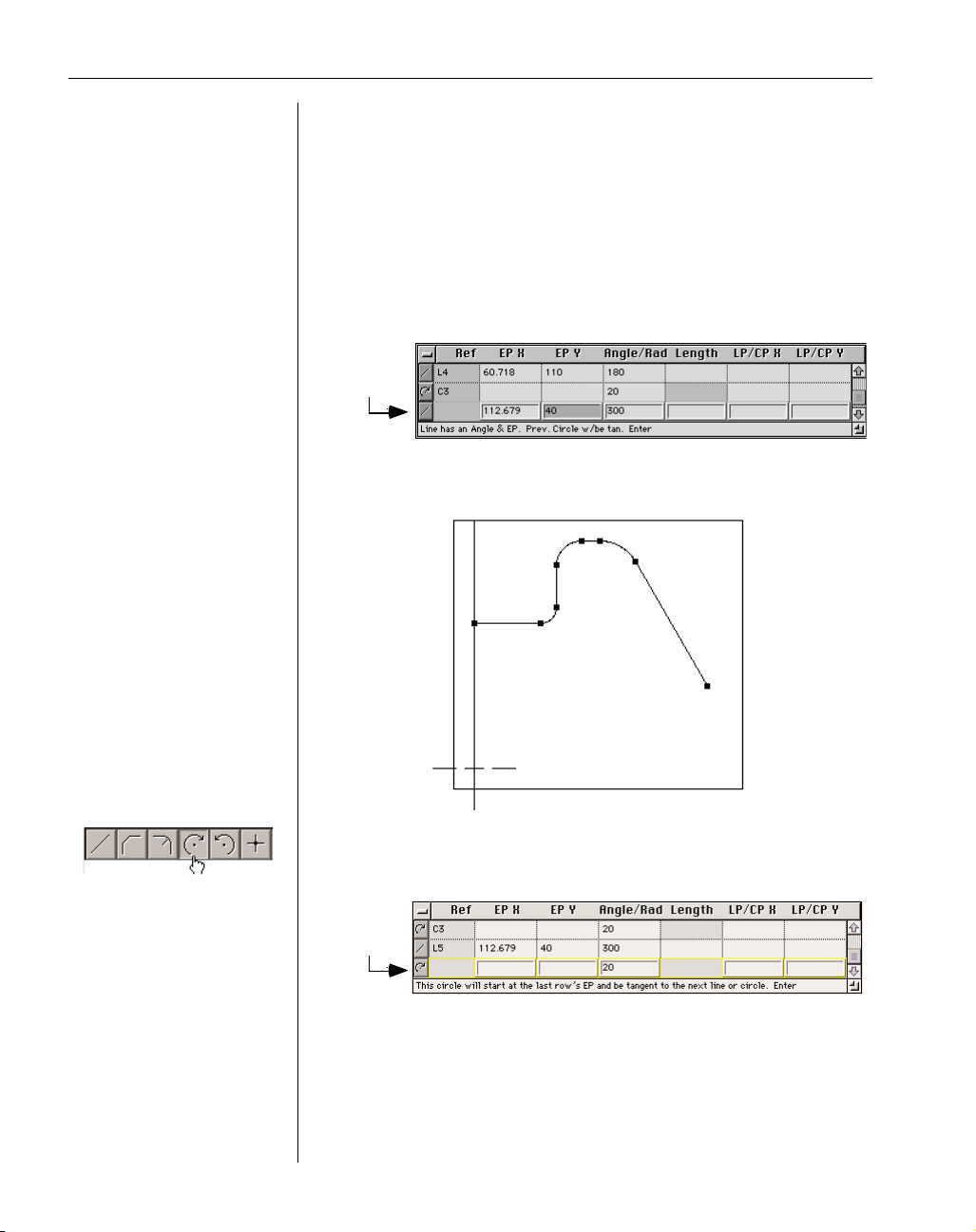
◆
Level 0 Milling GFK-1702
46
entered. We had to use an arc feature type rather than a fillet because
this arc is not tangent to the preceding and following lines.
• Hit the enter or return key.
Because the arc is dependent on the following line for a tangency
point, it will not be drawn on the screen until the following line is
defined.
• Enter the endpoint and angle value shown below.
• Hit the enter or return key.
• Select the Clockwise Arc feature type and enter the radius value shown
below.
• Hit the enter or return key.
Current
Row
Current
Row
Page 49

GFK-1702 Geometry Creation
◆
47
• Enter the angle and line point values shown below.
• Hit the enter or return key.
Your screen should look like the picture shown below.
• Select the Close Shape feature type.
The Close Shape feature type connects the first feature and the last
feature at their point of intersection or tangency by creating a connector point. No information other than the feature type needs to be
entered, and therefore all the cells in a Close Shape feature row are
grayed out. Closing the shape will usually be the final step when
creating a shape using Geometry Expert.
Current
Row
Page 50

◆
Level 0 Milling GFK-1702
48
Notice the fillet we created at the beginning of the exercise has now
been drawn.
Our shape is now closed, however, we forgot to create the fillet
between the first and last feature. We will add this fillet by inserting
a row in the spreadsheet. The Edit menu contains items for inserting
and deleting rows from the Geometry Expert spreadsheet.
• Select the Insert Row item from the Edit menu.
A blank feature row will be added to the spreadsheet above the current row. The inserted row is now the current row.
• Select the Fillet feature type.
The radius value for the fillet will default to the previous radius
entered for a fillet. Therefore, it is not necessary to enter a radius
value.
The fillet will be drawn immediately because it is being created
between two fully connected features. When rows are added to the
Current
Row
Current
Row
Page 51

GFK-1702 Geometry Creation
◆
49
spreadsheet, the system will scan the existing shape and attempt to
incorporate the inserted feature into the connected shape while maintaining all intersections and tangencies. If this is not possible the
system will produce an error message alerting the user.
• Hit the enter or return key.
The shape is now complete and fully connected and should look like
the picture shown below.
Page 52

◆
Level 0 Milling GFK-1702
50
EXERCISE BLUPRINT
110
R20
R20
R12
60.718
R12
40
30¡
40
112.67970
R12
R12
Page 53

GFK-1702 T ool Creation
◆
51
CHAPTER 5
:
Tool Creation
TOOL CREATION OVERVIEW
Depressing the Tool List Button in the Top Level Palette will bring up the Tool
List. The Tool List can hold up to 999 tools in a part file. Double-clicking on a tile location will bring up a Tool Creation Dialog. This dialog is used to create and modify tools.
Once the tool information has been entered and the dialog closed, a Tool Tile will be
created which displays the tool type and tool diameter. To index through the various
tools that have been created, click on the scroll arrows located at the top and bottom of
the Tool List.
Tools can be reorganized in the list at any time, even after operations have been
created, without reprocessing the operations. To reorganize the order of tools, click once on the Tool
Tile to be moved and drag it to an insertion point. The system will automatically adjust the operations to reflect the change in tool order and number. For more information on Tile Lists refer to the
Interface Chapter.
Tool specifications can be modified at any point during part creation. However, if operations
have been created using the tool, those operations must be reprocessed. To reprocess an operation,
double-click on the Operation Tile in the Operation List, and click on the Redo it button. The new
tool specifications will be incorporated into the new operation(s) toolpath.
TOOL CREATION DIALOG
All tools are created using the Tool Creation Dialog shown below. Each of the items contained
in the dialog is described in the following section.
Tool Type
Tool Length Offset
CRC Offset
Tool Diagram
Tool Material
Pop-up Menu
Spindle Direction
Page 54

◆
Level 0 Milling GFK-1702
52
Tool Type : The buttons in this area are used to select the tool type. The
picture and required information for the tool diagram will change
depending on the tool type selected. To select a tool, click on the appropriate tool type button.
Tool Diagram : The diagram and the necessary tool specifications change depending on the tool type
selected. The tool types, detailed below, are divided into four general groups based on the similari-
ties of the tool diagrams and specifications.
TOOL TYPE 1
Roughing Endmill
Finishing Endmill
Ball Endmill *
* Ball Endmills do not have a bottom corner radius specification.
Cutting
Diameter
Bottom Corner
Radius
# of Flutes
Tool Length
Flute Length
Page 55

GFK-1702 T ool Creation
◆
53
TOOL TYPE 2
Shell Mill Keyway Cuter *
Face Mill Thread Cutter *
Fly Cutter Back Bore *
* Keyway Cutter has a top corner radius specification; Thread Cutter has a Thread Form angle
instead of a bottom corner radius; and Back Bore has no bottom corner radius specification.
TOOL TYPE 3
Standard Drill Tap *
Center Drill Rigid Tap *
Spot Drill Countersink *
* Tapping tools have a TPI (Threads Per Inch) specification. Countersinks have a flat tip
diameter specification that is interactive with the tool length.
Tool Length
Shank Diameter
Cutting Diameter
Bottom Corner
Radius
# of Flutes
Flute Length
Tool Length
Cutting
Diameter
Tip Angle
# of Flutes
Page 56

◆
Level 0 Milling GFK-1702
54
TOOL TYPE 4
Boring Bar/Boring Head
Reamer
Spot Facing Tool *
* Spot Facing Tool has a bottom corner radius specification.
Spindle Direction : The CW and CCW buttons specify the spindle direction used
with the selected tool.
Tool Material : This is a pop-up menu used to specify the material of the tool.
Tool Length Offset Number : The number entered here designates the
numeric location in the machine where the Z offset amount is
entered.
CRC Offset Number : This number designates the numeric location in
the machine where the XY offset amount for CRC is found.
Comment : This is a comment associated with each tool. It will be output in the finished code at the
beginning of every operation that uses the tool.
TOOL LIST SUMMARY
Selecting Tool List Summary from the part menu (the title of this
menu will be the name of the file) will bring up the Tool List
Summary Dialog which provides information in a spread sheet format about each tool contained in the Tool List. When the summary
is open on the screen, the information can be printed. To print the
summary, select Tool List Summary from the Print sub-menu in the File menu.
Tool Length
Tool Diameter
# of Flutes
Page 57

GFK-1702 T ool Creation
◆
55
TOOL OFFSET
When pocketing or contouring, the system calculates a tool offset amount based on the radius
of the tool. This is the amount the finishing pass of the toolpath (the only pass if contouring) will be
offset from the selected part geometry. If a stock amount is entered for the process, that stock
amount will be added to the tool radius offset.
Normally, the tool offset amount is the tool radius which is taken directly from the information
entered in the tool creation dialog. When milling with tools with a bottom corner radius the system
calculates the tool offset based on the Floor Z compared against the Surface Z. The Surface Z is the
top surface of the material. The Floor Z specifies the finished depth of the pocket or contour. These
values are entered in the Contouring and Roughing Process Dialogs in the Entry/Exit Clearance
Diagram which is shown below.
The tool diameter used to calculate the offset amount is the diameter of the tool at the Surface
Z. In order for the system to correctly calculate the tool offset when using these tools, accurate Floor
Z and Surface Z positions must be entered in the Process Dialogs.
This offset calculation is useful when cutting pockets shallower than the corner radius on the
tool.
Surface Z
Floor Z
Tool Diameter
Surface Z
Floor Z
Diameter used to
calculate tool offset
Material
Page 58

◆
Level 0 Milling GFK-1702
56
CUTTER RADIUS COMPENSATION (CRC)
There is a preference which specifies how the system will handle CRC with Contouring and
Thread milling operations only. From Tool Center is the recommended option because that is the
method used by the system to display the toolpaths and cut part rendered images regardless of the
setting of the Cutter Comp Preference, which only affects the posted output.
When the From Tool Center item is selected, the numbers generated in the posted code will be
the geometry offset by a tool radius (providing the Stock amount is 0). From Tool Center is the rec-
ommended selection for this preference. When the From Tool Edge item is selected, the numbers
generated in the posted code will be the same as the blueprint numbers.
Roughing operations will always be calculated from the tool center. If the From Tool Edge
item is selected for this preference, CRC should be turned off in all roughing operations.
When using From Tool Center, the offset in the CRC register at the control should be the dif-
ference between the radius of the actual tool used and the radius of the tool programmed in the system. If the tools are identical, the CRC offset number should be 0. If the actual tool is smaller, a
negative value can be used.
When using From Tool Edge, the radius of the actual tool used should be entered in the CRC
register. If tapered tools or tools with corner radii are used, the user must calculate the appropriate
offset amount based on the taper. The system does not do this, as it does when From Tool Center is
selected.
WARNING: The system does a much better job offsetting the tool than the majority of controls cur-
rently available. Regardless of the setting made in this preference, all toolpath drawing and cut part
rendering will be calculated and displayed using the system’s offsetting mechanism. Therefore, it is
possible for the cut part rendered image produced by the system to look good, while the tool, cutting
according to the posted code, will not cut well. If the control’s offsetting mechanism is less
advanced than the system’s, it is possible when the control produces the offset values, errors and
interference will result.
Page 59

GFK-1702 Machining
◆
57
CHAPTER 6
:
Machining
MACHINING OVERVIEW
Depressing the Machining Button will bring up the Process List, the Machining
Palette, and the Operations List. The Process List is used to build up sets of operations
to be performed on geometry. The Machining Palette contains Function Tiles that combined with Tool Tiles create Process Tiles. Process Tiles are then used to generate
machining operations. A Process Tile is a temporary object that is used to create and
edit the final machining operations. When an operation is complete, an Operation Tile
which contains the finished toolpath will appear in the Operations List. Process Tiles
can be thrown away or modified to create different operations. The Operations List contains the completed machining operations that will be output during post processing.
CREATING AN OPERATION
Each tile in the Process List will be applied to the selected geometry. A Process Tile is created
by dragging a Function Tile from the Machining Palette and a Tool Tile from the Tool List to the
same location in the Process List. They can be dragged in any order. When a Process Tile is complete, a Process Dialog specific to the chosen Machining Function will appear. This dialog contains
detailed information about the way the toolpath will be created.
Once the Process Dialog is complete, a cut shape must be defined. The cut shape is the geometry the process will be applied to. Roughing operations require that a closed shape be selected for
pocketing or the stock shape can be selected for face milling. Drilling and thread milling operations
require that points or circles be created at the location of the holes to be drilled or threaded. For contouring operations, if a single shape is being machined the cut shape must be defined with the
Machining Markers.
Clicking on the Do it button applies the entire Process List to all selected geometry, creating as
many operations as are required. Operation Tiles will be created and placed in the Operation List. If
any completed Operation Tiles are highlighted, the Do it button will become the Redo it button. If
any changes are made to the information in the Process List and the Redo it button is depressed, the
selected operations will be replaced by the new operations. Therefore, once operations have been
satisfactorily created in the Operations List, the completed Operation Tiles must be deselected so
that they are not affected by changes made in the Process List when creating new operations.
Clicking on an empty tile location or clicking on an insertion point between locations will deselect
all Operations Tiles.
The Process List can then be set up to create a new set of operations. Process Tiles that were
used to create previous operations can either be thrown away or modified. Whenever the Do it or
Redo it button is depressed, ALL the Process Tiles in the Process List are used to create operations,
even if operations have already been created using those tiles. To be safe, it’s a good idea to throw
away the Process Tiles once the operations have been created and deselected. This way no duplicate
operations will be created because process tiles were left in the process list.
Operations contain the finished toolpaths. The toolpath consists of the actual moves the tool
will make to cut the part.
Page 60

◆
Level 0 Milling GFK-1702
58
MULTIPLE PROCESS PROGRAMMING
The Process List can be used to create groups of operations. A drilling process will drill all
selected points or circles. A contouring process will make a finish pass around a shape. A roughing
process tile will machine any number of closed shapes or face mill the entire stock shape. A thread
milling process will thread mill all selected points or circles.
If multiple Process Tiles of the same type are used in the same Process List, each tile will be
applied to the selected geometry. For example, three drilling processes can be used to drill, tap, and
counterbore the same points or circles. Three separate operations will be created to perform each of
these functions.
When multiple Process Tiles of different types are used in the same Process List, the effects of
each process will change depending on the other processes in the Process List. If a drilling process
is combined with a roughing or contouring process, the drilling process will drill entry holes for the
other process. If a contouring process is combined with a roughing process, the contouring process
will take one finish pass around the wall of all selected pockets and bosses.
When multiple operations are created from the same Process List, they will be linked. Doubleclicking on a linked Operation Tile will select all of the other operations created by the same
Process List. The Process List will be rebuilt and the geometry reselected. The link will be preserved even if the operations are reorganized in the Operations List.
MODIFYING AN OPERATION
Double-clicking on an Operation Tile in the Operation List will recreate all the Process Tiles
that were in the Process List when that operation was created. It will also select the geometry, and
reposition the machining markers (if any were used) as they were when the operation was
processed. Any operations created from the same Process List as the selected operation will also
become selected. The Do it button will be replaced by the Redo it button. Clicking on the Redo it
button after the changes have been made to the process information will replace all selected operations with the modified operations.
Changing specific information about an operation after it has been created can be accomplished using the Operation data item in the Modify menu. Operation data allows the user to change
and lock values, such as clearance planes and feeds and speeds. Locked items will NOT be affected
if the operation is reprocessed. This is useful when multiple operations are created from a single
Process Tile because changes can be made to one operation without changing the other operations
created from the same process. For more information, refer to the Operation Data section in this
chapter.
Page 61

GFK-1702 Machining
◆
59
MACHINING PALETTE
Each tile in the Machining Palette has a different function. The drilling function is used to drill
holes at defined point or circle locations. Multiple drilling operations created from one process list
generate a subprogram or a subroutine of the selected pattern of points or circles in the posted output.
The drilling function can also be used in conjunction with the roughing and contouring functions to
drill entry holes. The contouring function is used for taking a single pass along a shape. The roughing
function is used to remove material from the inside of a closed shape or to face mill. The thread
milling function is used to create ID and OD threads at defined point or circle locations.
The Do it button creates operations once Process Tiles are completed and a cut shape is selected.
The Do it button changes to the Redo it button when existing Operation Tiles are selected to indicate
that these operations can be reprocessed.
The Sort Ops button reorganizes the Operation List. The order of machining in the finished NC
program is the same as the operation list. Therefore, the order of Operation Tiles in the Operation List
is very important. Efficient use of multiple process programming frequently produces operations in a
poor machining order. Operations can be organized anytime during the programming of the part.
Clicking on the Sort Ops button reorganizes all operations by tool number and creation order.
When the Sort Ops button is depressed, the system examines all the operations and tries to group them
by tool number to minimize the number of tool changes. If an operation was created by the same
Process List as another operation, their order in the Operation List will be based on their order in the
Process List when they were created. For example, finishing operations will never be placed before the
roughing operations they follow in a process list. Operations can be manually reorganized by dragging
them to different locations in the Operations List.
PROCESS DIALOGS
Process Dialogs appear on the screen when a Function Tile from the Machining Palette and a
Tool Tile from the Tool List are dropped in a Process List Location. There are four Process Dialogs
that correspond to the four Functions Tiles in the Machining Palette. They are drilling, contouring,
roughing, and thread milling. Each is described in this section.
Drilling
Function
Contouring
Function
Pocketing
Function
Thread milling
Function
Do it (Redo it)
button
Sort Ops
button
Page 62

◆
Level 0 Milling GFK-1702
60
DRILLING PROCESS
The drilling process is used to drill, tap, or counterbore selected points or circles or
drill entry holes for other processes. When the Drilling Function Tile is combined with a Tool Tile,
the Drilling Process Dialog, shown below, will appear on the screen.
Entry/Exit Cycle : The selections made here determine the cycle the drill
will use to make its entry and exit moves. The choices include: Feed
In-Rapid Out, Feed In-Feed Out, Tap, Rigid Tap, Peck Full Out, and
Peck Chip Breaker.
Drill Clearance Diagram : The
Entry Clearance and Exit
Clearance specify the posi-
tions that the tool may use
when approaching and
retracting from the part.
The four values, described
below, are interactive and
calculated from the tool
information and the other
values entered. Drill Surface Z specifies the Z position of the top surface of the material. Spot Diameter
specifies the diameter of the hole at the Surface Z. This is useful when counter-sinking. Full Diameter
Z specifies the lowest Z depth the full diameter of the tool will plunge when drilling. Sharp Tip Z
specifies the final Z depth of the tool tip, and is the number that will be used in the posted output of
the finished code. If a Full Diameter Z is entered, the Sharp Tip Z will be calculated from the tool
diameter and the tip angle, otherwise the user can simply enter the desired Sharp Tip Z. The first
Entry Clearance
Plane
Spot Diameter
Drill Surface Z
Clearance Plane Z
Retract
Exit Clearance
Plane
Full Diameter Z
Sharp Tip Z
Entry Clearance
Retract
Page 63

GFK-1702 Machining
◆
61
Retract to Z value is the Z value entered for the Entry Clearance Plane in this dialog. If this option is
selected, the drill will move to the Entry Clearance Plane when making inter-hole moves. The sec-
ond Retract to Z option is the Z position entered in the Document Control Dialog in the Clearance
Plane Z text box. If this option is selected, the drill will move to that clearance plane position when
making inter-hole moves.
Clearance : This text box is only active if Peck Full Out is selected for
the Entry/Exit Cycle. The value entered specifies the incremental dis-
tance away from the material from which the tool will start its next peck.
Peck : This text box is only active when either Peck Full Out or Peck
Chip Breaker is the selected Entry/Exit Cycle. The value entered
specifies the depth the tool will plunge on each peck.
Retract : This text box is only active if Peck Chip Breaker is the select-
ed Entry/Exit Cycle. The value entered specifies the amount the tool
will retract after each peck.
Dwell : The value entered in this text box allows the user to specify the
amount of time in seconds the drill will pause at the bottom of the hole with
the spindle on. Dwell is only active when either FI-RO or FI-FO is the selected Entry/Exit Cycle.
RPM : The RPM value is the rate of the spindle measured in revolutions
per minute. The Material Database can be used to calculate this value.
See the Material Database section in this chapter for more information.
Feed : The Feed value specifies the inches per minute the tool will
plunge. Feed is only active when the selected Entry/Exit Cycle is FI-RO,
FI-FO, Peck Full Out, or Peck Chip Breaker. The Material Database can be used to calculate this
value. See the Material Database section for more information.
Tap % : The value entered here specifies the percentage of the feed rate
that will be used on the tapping cycle. This text box only appears if
Tap is the selected Entry/Exit Cycle.
Coolant : A yes/no button which indicates whether coolant is turned on
in a process. Flood is the standard coolant option.
Page 64

◆
Level 0 Milling GFK-1702
62
CONTOURING PROCESS
The contouring process is used to take a single pass along a shape or to machine multiple shapes with the tool on center (engraving). When a Contouring Function Tile is combined with
a Tool Tile, the Contour Process Dialog, shown below, will appear on the screen.
Entry/Exit Clearance Diagram:
The Entry Clearance Plane specifies the location the tool will
make a rapid move to before
feeding to the start point of
the toolpath. The Exit Clearance
Plane specifies the location the tool may rapid to after completing the toolpath. The Surface Z specifies the top level of the material and the Floor Z specifies the finished depth of the pocket.
Speed : The value entered is the rate of the spindle measured in revolutions per minute.
Entry Feed : This value designates the rate measured in feet per
minute (meters per minute if working in metric) that the tool will
be moving when it enters the material.
Contour Feed : The value entered here is the rate measured in feet
per minute (meters per minute if working in metric) that the tool
will be moving when cutting the toolpath.
Entry Clearance
Plane
Surface Z
Exit Clearance
Plane
Floor Z
Page 65

GFK-1702 Machining
◆
63
Entry Move : The Entry Move radio buttons instruct the system to
create additional geometry to add to the toolpath. When the first
option is selected, a 90° arc of the specified radius will be added
at the beginning of the toolpath. This arc will be tangent to the
start feature at the start point. If a value is entered in the Line
text box, a line of the specified length will be created tangent to
the arc as the first move in the toolpath. When the second option is selected, a line of the specified
length will be added to the toolpath. This line will be perpendicular to the start feature at the start
point. Entry/Exit lines are useful when using Cutter Radius Compensation (CRC), because typically,
CRC is turned on and off on the first and last line moves of the toolpath.
Exit Move : The Exit Move radio buttons instruct the system to
create additional geometry to add to the toolpath. When the first
option is selected, a 90° arc of the specified radius will be
added at the end of the toolpath. This arc will be tangent to the
end feature at the end point. If a value is entered in the Line text
box, a line of the specified length will be created tangent to the
arc. When the second option is selected, a line of the specified length will be added to the cut shape.
This line will be perpendicular to the end feature at the end point.
Stock ± : The value entered specifies the amount of material left on
the part geometry after the completed toolpath. A positive value will
offset the tool away from the geometry leaving material on the wall. A negative value will move the
toolpath into the geometry. A negative value can never be greater than the tool diameter.
CRC On : A yes/no button that indicates whether Cutter Radius Compensation is
turned on or off. For most post processors, CRC will be turned on and off on the
first and last line moves of the toolpath.
Coolant : A yes/no button which indicates whether coolant is turned on
in a process. Flood is the standard coolant option.
Page 66

◆
Level 0 Milling GFK-1702
64
ROUGHING PROCESS
The roughing process is used to create pockets and bosses by removing material from
the inside of a closed shape or to clear material from the face of a part. When the Roughing
Function Tile is combined with a Tool Tile and the Pocketing option is selected, the Roughing
Process Dialog, shown below, will appear on the screen.
Process Type : These radio buttons determine whether the process will generate
a roughing or face milling cycle. The default selection is pocketing. When
Face Milling is selected, the bottom half of the dialog changes. The informa-
tion for face milling cycles is described after the pocketing information.
Entry/Exit Clearance Diagram :
The Entry Clearance Plane
specifies the Z position the
tool will make a rapid move
to before feeding to the oper-
ation start point. The Exit
Clearance Plane specifies the Z position the tool may rapid to after completing the toolpath. The
Surface Z specifies the top level of the material and the Floor Z specifies the finished depth of the
pocket.
Speed : The value entered is the rate of the spindle measured in revolutions per minute.
Entry Clearance
Plane
Surface Z
Exit Clearance
Plane
Floor Z
Page 67

GFK-1702 Machining
◆
65
Entry Feed : This value designates the rate measured in feet per
minute (meters per minute if working in metric) that the tool will
be moving when it enters the material.
Contour Feed : The value entered here is the rate measured in feet
per minute (meters per minute if working in metric) that the tool
will be moving as it cuts the pocket.
Cut Width : The value entered specifies the width the tool will move
out on each pass. This value automatically defaults to half of the tool
diameter. If the value is made smaller, the passes will overlap. If the value is made larger, areas may
be left uncut.
Entry/Exit Moves : The values entered in these text boxes add
radius and/or line moves at the beginning and end of the last
pass of the roughing toolpath. If a radius value is entered, a 90°
arc of the specified radius will be added at the beginning and
end of the finish pass of the pocket. If a line value is entered in
addition to a radius value, a line of the specified length will be added tangent to the entry/exit
radius. If an entry/exit radius is not being used, a line of the specified length will be added perpendicular to the first and last move of the finish pass on the roughing toolpath. Entry/Exit lines are
useful when using Cutter Radius Compensation (CRC) because typically, CRC is turned on and off
on the first and last line moves of the toolpath.
Stock : Different stock amounts can be entered for the wall of the
pocket and for any island or boss contained in the pocket. The
value entered for Pocket Stock is the amount of material that will
be left on the wall of the pocket. The value entered for Island Stock is the amount of material that
will be left around any bosses that are contained in the pocket, and are selected as part of the roughing cut shape. A positive stock amount will leave material on the pocket or island and a negative
stock amount will cut into the pocket geometry.
Cut Direction : These radio buttons allow the user to designate the direction the
tool will travel, either making a climb cut or a conventional cut.
CRC On : A yes/no button that indicates whether Cutter Radius Compensation is
turned on or off. For most post processors, CRC will be turned on and off on the
first and last line moves. If the From Tool Edge option is selected for the Cutter Comp Preference,
CRC should be turned OFF for all roughing operations. Refer to the Menus Appendix under
Preferences for more information.
Coolant : A yes/no button which indicates whether coolant is turned on
in a process. Flood is the standard coolant option.
Page 68

◆
Level 0 Milling GFK-1702
66
FACE MILLING
The face milling item completely automates clearing material from the face of a part. When
the Face Milling option is selected, the bottom portion of the Roughing Dialog changes, as shown
below. Each of the face milling features is described below. The other items contained in the dialog
function as they do when performing a pocketing roughing operation.
Shape Selection : If the Stock option is selected, no geometry needs to be selected.
The process will face the entire stock shape. If the Shape option is selected, a
closed shape must be selected. The system will face the selected closed shape.
Start Corner : These radio buttons determine the start point of the toolpath. The
selections indicate in which corner of the shape, whether it be the entire stock
shape or a selected closed shape, the tool will start cutting. For example,
selecting X+, Y+ will begin the toolpath in the upper right hand corner; X+, Ywill begin the toolpath in the lower right hand corner, and so on. The four possible combinations
represent the four quadrants.
Cut Options : These selections indicate how the toolpath will be generated
and determine the finish of the cut as well as the length of the roughing
cycle. Each selection is described below.
Spiral In : This option generates the fastest roughing cycle, but produces a rougher surface
finish then some of the other options. The tool starts off the part and ends on the part. The tool
spirals into the material and makes a square pattern to remove the material.
Zig Zag : This option also generates a fast roughing cycle, but a rougher finish. The tool starts
off the part and ends off the part. The tool zig zags across the material alternating between
climb cutting and conventional cutting.
Page 69

GFK-1702 Machining
◆
67
Back & Forth : This option produces a better surface finish because the tool is always climb
cutting. The toolpath alternates cutting from both ends of the part.
1 Direction : This option produces the best surface finish, but generates a slower roughing
cycle. The tool makes one pass across the part, rapids up and back across the part, and then
makes each additional pass to clear off the necessary material.
First Cut : The available choices change depending on the Start
Corner selections. These buttons determine the direction of the first
cut.
Clearance : The Clearance amount entered is an XY offset
value that is added to the beginning of the toolpath. The toolpath is always offset from the stock shape or selected geometry by a tool radius. The Clearance
value is added to the tool radius offset amount.
Rapid In : When Rapid In is turned on, the tool will rapid from the Entry
Clearance Plane to the starting Z depth of the toolpath. When turned off, the tool
will feed from the Entry Clearance Plane to the start point of the toolpath.
THREAD MILLING PROCESS
This function, in conjunction with the thread milling tool, allows the user to easily
mill OD and ID threads. The thread milling process is similar to the drilling process in that it
requires that either points or circles be selected for the cut shape. Each of the items in the thread
milling dialog is described below.
Thread Type : This selection determines whether an OD or ID thread will be created. The
Thread Mill Entry/Exit Diagram will change depending on the selection made. The picture above shows an OD Thread Mill Entry/Exit Diagram.
Page 70

◆
Level 0 Milling GFK-1702
68
Thread Mill Entry/Exit Diagram :
The
Entry
and
Exit Clearance Planes
function as they do in the other
Process Dialogs. The
Thread Start Point and Thread End
Point positions entered in the dia-
gram specify the actual start and end of the thread specified on the blueprint. The system will add a
45° helix to the start and end of the threading toolpath to provide for a smooth transition into the
thread. The start and end points of this helical entry move will be higher and lower in Z than the
actual Thread Start and End Points entered by the user in the dialog. The tool can thread up or
down, meaning that the start point can be at a higher or lower Z position than the end point.
Thread Direction : This selection determines whether the thread will be created in a
clockwise or counter-clockwise direction.
Cut Diameter : On an OD thread, the tool cuts in to the cut diameter. On an ID thread, the tool cuts out to the cut diameter.
Clearance Diameter : On an OD thread, the tool will retract to the
Clearance Diameter after completing the thread, before going to
the exit clearance position. On an ID thread, the Clearance Diameter should be equal to or less than
the size of the hole that is being threaded. For ID threads, the tool diameter < clearance dia < cut
diameter. For OD threads, cut diameter < clearance diameter..
TPI (Threads Per Inch) : This value specifies the number of threads
per inch. The threads per inch and pitch text boxes are interactive.
When one value is entered the system calculates the other. This allows the user to enter whatever
specification is given on the blueprint, whether it be pitch or TPI. When creating a metric part, this
value specifies threads per millimeter.
Pitch : This value specifies the pitch of the thread which is calculated by taking the inverse of the TPI.
OPERATION DATA
It is possible to edit certain operation specifications in the Operation Data Dialog. The values
in the text boxes with raised borders and the yes/no buttons that appear in the dialog with locks next
to them can be changed. Values are locked by clicking once on the lock next to the text box.
Unlocked values will return to their original values if the operation is reprocessed. Locked items
will retain the values entered in this dialog even if the operation is reprocessed. Changes that affect
the toolpath can be seen in the toolpath drawing and the rendered image. The information in the
process tile that created the operation will not be changed to reflect the changes made in the operation data dialog.
It is useful to change and lock values in the operation data dialog when multiple operations are
Entry Clearance
Plane
Thread
Start Point
Exit Clearance
Plane
Thread
End Point
Page 71

GFK-1702 Machining
◆
69
created from a single Process Tile. With this feature, it is possible to change certain specifications to
one operation without changing them to all the operations that were created with the same Process
Tile. For example, if multiple pockets are machined from one Process Tile, a separate operation is
created for each pocket. If an Entry or Exit Clearance Plane needs to be changed to avoid a clamp
between two of the pockets, this can be accomplished by changing the clearance values in the
Operation Data Dialog for one of the operations. The clearance values of the other roughing operations will be unaffected.
Information entered in the Op Comment text box will appear in the posted output before the
selected operation it refers to. Utility data can can also be entered in this dialog. Custom posts allow
the user to input custom commands in the At Op Start and At Op End text boxes that will trigger
actions inside the post processor. In addition, any text that appears in quotations in the At Op Start
and At Op End text boxes will appear in the posted output. Each set of quotes will be on a separate
line in the posted output.
The Program Stop yes/no button is only available in the Operation Data Dialog. If it is turned
on, a program stop command will be added at the end of the operation in the posted output. The
default position is off.
If operations contain locked values, a small lock symbol will appear on the Operation Tile. If
utility data is entered in the At Op Start text box, a small recessed square will appear on the
Operation Tile in the upper left hand corner. If utility data is entered in the At Op End text box, a
small recessed square will appear in the lower left hand corner of the Operation Tile. The Operation
Tile, shown below, displays these symbols.
CLEARANCE MOVES
This section details how the system handles tool moves between operations and between holes
in drilling cycles. The following conventions are used in the pictures shown below.
Dashed Arrow : Rapid Move
Solid Arrow : Feed Move
CP : Clearance Plane
SP : Start Point; the first move of the operation, not necessarily the location of the Start Point
Marker.
EP : End Point; the last move of the operation, not necessarily the location of the End Point Marker.
Op1 : Operation 1; the first series of cuts made on the part.
Op2 : Operation 2; the second series of cuts made on the part.
At Op Start Data
Locked Values
At Op End Data
Page 72

◆
Level 0 Milling GFK-1702
70
ENTRY MOVE : SAME TOOL
ENTRY MOVE : TOOL CHANGE
Tool Change
Position
Tool Change Z,
SP XY
Entry CP Z,
SP XY
Cut Depth Z,
SP XY
Exit CP Z
EP XY, Op 1
Exit CP Z
SP XY, Op 2
Entry CP Z,
SP XY
Cut Depth Z,
SP XY
Page 73

GFK-1702 Machining
◆
71
EXIT MOVE : SAME TOOL
EXIT MOVE : TOOL CHANGE
Tool Change
Position
Tool Change Z,
EP XY
Exit CP Z,
EP XY
EP XYZ
Cut Depth Z,
SP XY
Entry CP Z,
SP XY, Op 2
Exit CP Z,
EP XY
EP XYZ, Op 1
Page 74

◆
Level 0 Milling GFK-1702
72
During a drilling cycle, the tool can retract to one of two different Z clearance planes when it
is making inter-hole moves. In the Drilling Process Dialog, there are two retract values. The top
retract value is the Entry Clearance Plane entered for the process. The bottom retract value is the
Clearance Plane Z specified in the Document Control Dialog.
MACHINING MARKERS
Machining Markers allow the user to specify the start and end feature and start and end point
of the cut shape, the cut direction, and the offset position of the tool. These markers appear on the
screen when geometry is selected for contouring processes.
Start Feature : The geometry feature (line or circle) on which the tool will start cutting.
Start Point : The point on the start feature where the tool will start cutting.
End Feature : The geometry feature on which the tool will stop cutting.
End Point : The point on the end feature where the tool will stop cutting.
Cutter Side and Direction : The circles represent where on the geometry the tool will
cut: on the outside of the geometry, on the inside of the geometry, or on the centerline. The arrows indicate which direction the tool will travel signifying whether
a climb or conventional cut will be made. Click on the desired circle and directional arrow.
Entry Clearance
Plane
Z Clearance Plane
Retract
Exit Clearance
Plane
Entry Clearance
Retract
Page 75

GFK-1702 Machining
◆
73
HOW MACHINING MARKERS WORK
Machining Markers appear on selected geometry for contouring processes in order to designate
the cut shape. To move a marker, place the cursor over the marker and depress the mouse button.
The cursor becomes the marker. This is called “picking up a marker”. The marker can then be
moved to the desired location. Release the mouse button to drop the marker.
When the Feature Markers are moved, the Point Markers “follow” them and snap to the same
position. To place the Start Point and End Point Markers in the exact same location, place the Start
Feature Marker in the correct location and drag the Start Point Marker to the desired position. Then
drag the End Feature Marker to the same location as the Start Feature Marker. The End Point
Marker will automatically snap to the same position as the Start Point Marker.
For precise control over the Start and End Point Marker positions, create a point at the correct
position. Dragging a Start or End Point Marker close to the point will cause the marker to “snap” to
the point and use its exact coordinates.
The geometry between the start and end points will be dark blue to indicate that it is the cut
shape that will be machined by the process. If the start and end features are the same, double-clicking on one of the markers will allow the toolpath to pass over the end point once. This will create an
overlap in the toolpath.
START AND END POINTS
The start and end points do not necessarily have to be on the part geometry. There may be
times when it is desirable to have the tool start or end its toolpath off the part. This can be done by
moving the markers off the part geometry. A geometry feature (e.g. line or circle) is trimmed
between two connectors. When the Start Point Marker is dragged off the part, it automatically snaps
to the nearest extension of the start feature. The nearest extension of the start feature may be a section that was trimmed away, so the start point will snap to an extension of the start feature off the
part. This is also true for the end feature and end point.
OPERATION SUMMARY
Selecting Operation Summary from the part menu (the title of
this menu will be the name of the file) will bring up the Operation
Summary Dialog which provides information in a spread sheet format
about each operation in the program, including estimated cut times
and the distance traveled by the tool. The information in the dialog
can be printed. To print the summary, select Operation Summary
from the Print sub-menu in the File menu.
Page 76

◆
Level 0 Milling GFK-1702
74
PRINTING THE TOOLPATH
After an operation has been created, the resulting toolpath can be printed. Toolpaths can either
be printed in black and white or color. When the desired toolpath is on the screen, choose Drawing
from the Print sub-menu in the File menu. To adjust the way the image will print, choose Printing
from the Preferences sub-menu in the File menu. The Printing Preferences Dialog specifies how the
system will handle the background color. If the printer being used is a black and white printer,
choose the Black on White option to ensure that all portions of geometry, including those that are a
light color, can be seen in the print.
For specific information regarding printing on the different operating systems, refer to the
Printing Appendix found at the end of this manual.
O
S
Page 77

GFK-1702 View Contro
l ◆
75
CHAPTER 6
:
View Control
VIEWING THE PART
The system provides for dynamic viewing of the part in any planar orientation. The
View Control Palette allows the user to change the view of the part by either clicking on
buttons which provide standard view changes, such as the top and side view, or maneuvering a small model of the part to any orientation. The part can be drawn, machined
and rendered in any view. The top view is recommended for creating geometry and
machining operations, while the isometric or “world” view is excellent for cut part rendering.
VIEW CONTROL PALETTE
Depressing the View Control Button brings up the View Control Palette that is used for changing the current view of the part. In the center of the palette is a “trackball”. Around the outside of
the trackball are additional buttons for controlling the view. The entire View Control Palette is often
referred to as the Trackball.
When the cursor is placed over the Trackball, the cursor changes into a hand which allows the
user to roll the Trackball and change the view. Holding down the mouse button and moving the
mouse will roll the Trackball. The black outlined box on the ball represents the orientation of the
part. The "T" identifies the top surface of the part. The dimensions of the box do not change with
the actual part size. X is always the longest axis; Y is the second longest; Z is the shortest.
Once the desired view is obtained and the mouse button released, the part will be redrawn in
the new view. The ball has four small solid black rectangles around the inside ring of buttons (located at 12:00, 3:00, 6:00, 9:00). These are called trackball handles. These handles can be dragged for a
single axis view change. The View Control Palette can be moved to any location on the screen by
dragging its edge.
Top View
Unzoom
Front View
Previous View
Redraw
Side View
Isometric View
Page 78

◆
Level 0 Milling GFK-1702
76
VIEW MENU
All of the buttons in the View Control Palette are also available as
items in the View menu. In addition, there are other items contained
in the menu that relate to the viewing and drawing of the part. Each
item in the View menu is described below.
Top View : This is the standard, default view of the XY plane.
Front View : This a view of the XZ plane.
Right View : This is a view of the YZ plane.
Isometric View : This is a “world” view. The part is drawn such that
the part dimensions are all foreshortened equally.
Unzoom : Also known as no zoom. This sets the scale of the view to
the maximum size that the monitor will allow. It is based on the
stock size and the current view.
Redraw : This item refreshes the screen image allowing the user to
get a better indication of what is currently drawn on the screen.
Geometry, toolpaths, or the rendered part image can be redrawn
using this item.
Previous View : This item changes the current view to the last view that was worked in.
Zoom In : This item increases the scale of the view so the drawing gets bigger by 25% each time it is
selected.
Zoom Out : This item decreases the scale of the view so the drawing gets smaller by 25% each time it
is selected.
Labels : If this item is turned on, labels will be drawn next to every geometry feature drawn. Circles
will be labeled C#, Lines L#, and Points P#. The # is determined by the order the points and features were created. It corresponds directly to the information shown in the Workgroup Summary.
Draw Points : If this item is turned off (not checked), all points will not be drawn on the screen.
Extend Lines : When this item is turned on, all unconnected lines will extend to the edge of the stock.
If it is turned off, lines will only extend to the features they were created between.
Show Stock & Origin : The default has this item turned on. If it is turned off, the gray outline of the
stock and the origin marker will not be drawn on the screen.
Page 79

GFK-1702 View Contro
l ◆
77
Show Geometry : This item redraws only points, lines and circles. It will draw geometry over the cut
part rendered image of the part.
Shrink Wrap : When this item is selected, the software will examine all geometry and adjust the stock
size to show all the geometry on the screen without excess blank space.
Page 80

◆
Level 0 Milling GFK-1702
CHAPTER 7
:
Cut Part Rendering
CUT PART RENDERING OVERVIEW
Modeling is the process of defining a three dimensional object. Rendering is the
process of displaying a picture of this model. A cut part model is defined when the operations necessary to machine a part have been created. The computer has 3D knowledge
of the inside of the model; even of the areas that are not visible.
The cut part rendering capability in the system is called Three Dimensional Real
Time Cut Part Rendering. Three dimensional refers to the the fact that the model can be
rotated around in space and viewed at any angle. Real Time refers to the speed at which
the part is rendered. The cutting action is rendered as it is calculated rather than calcu-
lating the rendered image and then playing back a "movie", or just displaying a picture of the finished model. Real Time does NOT mean actual feed rates are used. The tool is cutting as fast as the
computer can calculate the moves. Cut Part refers to watching the effect of the tools cutting, as
opposed to seeing only the finished picture. Seeing the cutting process is more valuable, in most
cases, than the finished picture. Rendering refers to the process of displaying the graphic image of
the cut part model defined by the machining operations.
All operations will be rendered in their current order. The rendering process will start over
whenever the view is changed or zoomed. Therefore, it is more efficient to select the desired view
before depressing the Cut Part Render Button. Selected operations will render in shades of yellow,
all others will render in shades of grey. Shades of red will be drawn when non-cutting tool surfaces
or rapid moves hit the material. Selected tools will be drawn in shades of yellow. Unselected tools
will be drawn in shades of grey. Smaller pictures will render faster and use less computer memory.
CUT PART RENDERING PALETTE
When the Cut Part Rendering Button is depressed, the Cut Part Rendering Palette appears on
the screen, and the stock shape will be displayed as a blue, 3D solid image. The Cut Part Rendering
Palette controls the cut part rendering process. The functions of the items in the palette are described
below.
Operation Box : This box displays the number of the current operation being rendered.
Rewind : This button sets the current operation to the first operation. If the Play button is down when
the Rewind button is depressed, the part will be redrawn.
78
Rewind Step Forward
Operation Box
Invisible Tool
Transparent Tool
Stop Play
Visible Tool
Next Operation
Throttle Control
Page 81

GFK-1702 Cut Part Rendering
◆
Stop : This button stops any rendering in progress and raises the Play button.
Step Forward : This button renders the next feature of the current operation. If the Play button is
depressed, it will be raised and rendering will be stopped at the end of the current feature.
Play : When the play button is depressed, the part will be rendered from the current feature of the
current operation as listed in the operation box. Rendering will continue until one of the other buttons is depressed or the last feature of the last operation is rendered. The Stop and Step Forward
buttons stop the rendering and raise the Play button. The Next Operation and Rewind buttons will
change the current operation being rendered, but will not stop the rendering process. When the last
feature of the last operation is completed, rendering will stop, but the Play button will remain
depressed. Anytime the rendering process stops, hitting the Play button again will resume rendering
from the current location.
Next Operation : If the Play button is depressed, the current feature being rendered is finished and the
remaining features for that operation are skipped. The next feature to be rendered is the first feature
of the next operation. If the Play button is not depressed, the current operation is set to the next
operation. The Operation box will be updated, but nothing will be rendered until the Play button is
depressed again.
Throttle Control : Shows the current location of the Throttle slider. The plus side represents maximum
rendering speed, and the minus side the minimum. The location of the slider can be changed by
dragging it left or right. This can be done during the rendering process and the effects will be seen
as the slider is moved.
Invisible Tool : When this button is
depressed, the tools will not be drawn
during the rendering process, although
the material removed as a result of the
tool is shown (see example at left).
79
Page 82

◆
Level 0 Milling GFK-1702
Transparent Tool : When this button is
depressed, transparent tools will be
drawn during the rendering process (see
example at left).
Visible Tool : When this button is
depressed, solid tools will be drawn during the rendering process (see example at
left).
During the cut part rendering process, if the screen is redrawn due to a view change or redraw,
the rendering process will start over from the first operation. Therefore, it is a good practice to set
the desired view before rendering the part.
When the rendering process is stopped by pressing either the Stop or Step Forward button, the
next time the part is rendered, the system will automatically stop the rendering process in the same
location. User set stops are maintained by the system. Anytime the rendering process is stopped, in
order to continue, simply click on the Play button again
If the Play button is depressed when the Cut Part Rendering Button in the Top Level Palette is
raised, it will be depressed when the Cut Part Rendering Button is selected once again. This means
that the next time the Cut Part Rendering Button is depressed, the rendering process will automatically start. If the view is exactly the same when the Cut Part Rendering Button is depressed as it
was when it was raised, the rendered part will immediately be drawn and any new or “incremental”
operations will be added.
80
Page 83

GFK-1702 Cut Part Rendering
◆
CUT PART RENDERING PREFERENCES
There is a Rendering option in the Preferences sub-menu under the File menu. If it is selected,
the following dialog box will appear.
By default, both options will be turned on. Turning off either or both will slightly decrease rendering times and memory requirements. Turning off Smooth Shading will reduce the quality of the
cut part rendered image. If the Tool Drawing Enabled option is turned off, the rendering process
will always be shown with an invisible tool. The software must be restarted for the changes to take
effect.
PRINTING THE CUT PART RENDERED IMAGE
After the Cut Part Rendering is complete, the rendered image can be printed in either black
and white or color. When the rendered image is on the screen, choose Drawing from the Print sub-
menu in the File menu. To adjust the way the image will print, choose Printing from the Preferences
sub-menu in the File menu. The Printing Preferences Dialog, shown below, allows the user to specify how the software will handle the background color. If the printer being used is a black and white
printer, choose the Black on White option to ensure that all portions of the image, including those
that are a light color, can be seen in the print.
For specific information regarding printing on the different operating systems, refer to the
Printing Appendix found at the end of this manual.
81
O
S
Page 84

◆
Level 0 Milling GFK-1702
CHAPTER 8
:
Post Processing
POST PROCESSING OVERVIEW
Once the operations to machine the part have been created, the file needs to be
post processed. Post processing converts a part file (VNC file) which contains the
machining operations (toolpaths) into a text file (NC program) that can be transferred to
the machine control. A Post Processor specific to the machine control is used to convert
the VNC file into a text file. Communicating the posted text file to the CNC machine is
discussed in the Communications chapter which follows this one.
POST PROCESSOR DIALOG
The Post Processor Button in the Top Level Palette becomes active once machining operations
have been created in a file. Clicking on the Post Processor Button will display the Post Processor
Dialog shown below. This dialog allows the user to specify a program name and format the output.
Clicking on the Process button will generate the NCprogram for the file currently open. The
text file will be saved under the file name displayed to the right of the Program Name button. If a
file with that name already exists, clicking the Process button will erase the old file and replace it
with the new one. To view the text file as it processes, click on the Text Window button. When this
button is depressed, a window will appear that displays the posted text file as it is created. The program will scroll by in the window as it is being generated. The Pause button allows the user to stop
the scrolling of the output as it is being processed. The Print button will be available after the program file is finished processing.
82
Communications Button
Program Name Button
Text Window Button
Page 85

GFK-1702 Post Processing
◆
Before posted output can be generated, the program file name must be specified. When a file is
post processed, a text file is created with the extension specified in the Post text box in the File
Extensions dialog. By default this extension is set to .NCF. A file can be post processed multiple
times, and saved with different .NCF file names. If changes are made to the part file, it must be post
processed again in order to incorporate the changes into the posted output. As a default, the text file
uses the part file name with an .NCF extension (e.g. EXAMPLE1.NCF). This file name can be
changed by clicking on the Program Name button and entering a new name.
To specify an output file name for the finished program, click on the Program Name button.
The system will automatically add the extension specified in the File Extensions dialog. Selecting
File Extensions from the Preferences submenu in the File menu will display the File Extensions dia-
log shown below.
POSTED OUTPUT FORMAT
The items in the top box of the Post Processor Dialog, shown below, change the format and
content of the finished output. Each item can react differently with different post processors. Below
is a description of the effect they will have with most post processors.
Starting Program Number : This is the number of the program as it will appear in the control. It is also
the starting number for all sub-programs. If the Starting Program Number is one, the first sub-program will be two, the second three, etc.
Sequence from : This is the starting number for the block numbers or “N” numbers. The by box deter-
mines the increment.
Moves ar Absolute: All tool moves will be from a single origin.
83
Page 86

◆
Level 0 Milling GFK-1702
Minimize : If this option is turned on, the post processor will only output block numbers on tool
change positions.
Insert Comments : This option will output information about each operation and tool used as well as
file length. If any additional comments have been entered by the user about tools or operations, they
will be output as well.
Insert Optional Stops at Tool Change Positions : If this option is on, the software will output a machine
operator selectable program stop at every tool change.
POST PROCESSOR PREFERENCES
Selecting the Post Processor item from the Preferences submenu under the File menu will
bring up the dialog shown below. These preferences allow the user to control the comments in the
posted output.
The dialog contains a number of yes/no buttons that provide various options for how comments will appear in the final posted output. Turning on one of the buttons so that it contains a red
dot will cause the post processor to output that comment.
84
Page 87

GFK-1702 Communications
◆
85
CHAPTER 9
:
Communications
The system contains integrated communications. Third party communications packages,
including Gibbs ncCommunications, can also be used to communicate with CNC machines.
Before a file can be sent to the CNC machine, the parameters for a file transfer need to be setup. This is done in the Com Set-Up Dialog. It is accessed from the Preferences sub-menu of the File
menu. This dialog is used to set up communication protocols needed for sending a program (text
file) to a control or receiving a program from the control.
PROTOCOLS
ADDING A PROTOCOL
A new protocol is added by typing in a new name and changing all of the settings to match
those of the CNC machine. Clicking on the Add button will add the protocol to the current database
of protocols.
After a protocol has been added, the name will appear in the upper left hand corner (as shown
above). Additional protocols can be entered and saved in the same manner. Saved protocols can be
accessed in the Protocol pop-up menu in the upper left hand corner of the dialog.
CHANGING A PROTOCOL
To change information about a protocol, select the protocol from the list and change the information. The changes are automatically saved when the dialog is closed or when a different protocol
in the list is selected.
Page 88

◆
Level 0 Milling GFK-1702
86
REMOVING A PROTOCOL
To remove a protocol, simply select the desired protocol from the list and click on the Remove
button.
COMMUNICATING WITH A CNC MACHINE
To send a file to or receive a file from a CNC machine, click on the Communications button in
the Post Processor Dialog.
COMMUNICATIONS DIALOG
This brings up the Communications Dialog. The Communications Dialog can also be accessed
from the File menu. Files can either be sent to the machine control or received from the control. The
File Type radio buttons indicate what type of file will be sent. When a file is post processed, a text
file (NCF file) is created. NCF (text) is the necessary selection when sending posted NCF files from
the computer to the control or vice versa. The VNC (binary) selection allows users to send and
receive VNC files, which are the actual part files that contain the geometry and toolpaths. VNC files
can be communicated between computers that have the system installed. This is especially useful
when the system is built into the control of a machine tool. Part files (VNC files) can be communicated in their entirety from a computer to the machine’s control, and from the control back to the
computer.
Communications Button
Text Window Button
Page 89

GFK-1702 Communications
◆
87
SENDING A FILE TO THE CONTROL
To send a file, the Send Mode button must be depressed. The protocol is chosen by using the
Protocol pop-up menu. The program to be sent is specified by clicking on the Program Name button. When everything is set correctly, click on the Send button to send the file. While the program is
being sent, the Send button becomes the Stop button. Click on the Stop button to stop the communication. The progress bar shows the status of the file being sent. If the Text Window is opened from
the Post Processor Dialog, the program will scroll by as it is being sent to the control.
SENDING OTHER .NCF FILES
Any text file that matches the extension set in the File extension preference dialog can be sent
to the control. Refer to the Post Processing Chapter for more information on output file extensions.
RECEIVING A FILE FROM THE CONTROL
To receive a file from the control, open the Communications Dialog from the Post Processor
Dialog or from the File menu. The Receive Mode button should be depressed. Choose the correct
protocol from the Protocol pop-up menu. The name of the received program is specified by clicking
on the Program Name button. When everything is set correctly, click on the Receive button, and
then send the program from the control. If the Text Window is open from the Post Processor Dialog,
the program will scroll by as it is received.
NOTE:
It is recommended that edited .NCF files received back from the machine control be saved
under a different name than the original .NCF file that was sent to the control. That way, if the original .VNC file is reprocessed, it won’t affect the edited .NCF file. For example, a part file named
SAMPLE.VNC is post processed and a text file named SAMPLE.NCF is created. Changes are made
to the program at the machine control and the new file containing those changes is sent back and
received at the offline computer, but under the name SAMPLE1.NCF (or something similar.) If
SAMPLE.VNC is reprocessed again at a later date, it won’t destroy the SAMPLE1.NCF file that
contains the changes made at the machine.
Send Mode button
Program Name button
Receive Mode button
Protocol pop-up menu
Progress Bar
Page 90

◆
Level 0 Milling GFK-1702
88
CHAPTER 10
:
Tutorial
The easiest and most effective way to learn the system is to
actually program a part, which is what we will do in this tutorial section. A simple mill part will be created. Step by step instructions are
provided to guide you through the setting up a part, creating geometry, tools and machining operations and post processing.
A blueprint of the sample part has been provided at the end of
the tutorial.
• Launch the system.
Refer to the Operating Systems Appendix for specific instructions on
launching the system.
CREATING A NEW PART
• Click on the Document Control Button in the Top Level Palette.
The Document Control Dialog, shown below, appears on the screen.
You can create new part files using this dialog and also open existing
files. Notice there is no part currently open.
• Click on the New button.
Page 91

GFK-1702 Tutoria
l ◆
89
• Type “Milltut” in the New File Name text box.
• Click on the Save button.
The top section of the Document Control dialog contains file management options, as well as measurement type. The bottom section
contains stock specifications, tool change and clearance positioning
information.
• Select the inches option for the measurement type.
• Enter the values shown below for the stock size and Z Clearance Plane.
The stock size will be used to draw the stock outline and origin
marker on the screen.
The Z Clearance Plane value is very important. This value indicates
where the tool will rapid to immediately after a tool change. It also
specifies the last rapid move the tool will make before going to the
Tool Change Position. Additionally, the tool will move to this position between drilling moves if the second Retract to Z option is
selected in the Drilling Process dialog. Refer to the Machining
Page 92

◆
Level 0 Milling GFK-1702
90
Chapter for more information on Clearance Moves and Drilling
processes.
• Click Tl Change Pos to the off position so that the button is raised and the
X and Y text boxes below it are grayed out.
The tool change position is used on milling machines without automatic tool changers. It is also used when the table must be moved to
avoid crashing during a tool change due to a tall part, fixtures, or a
rotary table.
• Type “This is a sample part” in the Comment box.
This box is for a part comment. If a part comment is entered, it will
appear in the Open Dialog when the part is selected.
When all of the information is entered, the Document Control Dialog
should look like the picture shown below.
• Close this dialog by either clicking on the Document Control Button in the
Top Level Palette, or clicking in the Close box in the upper right corner of the
dialog.
Page 93

GFK-1702 Tutoria
l ◆
91
Currently we are looking at the top view of the part, the XY plane. In
order to get a better visual picture of the part, we will change the
view.
• Click on the View Control Button in the Top Level Palette.
This will bring up the View Control Palette, also referred to as the
Trackball, which allows you to change views, redraw, and unzoom.
You can select the different options by clicking on their buttons.
For an explanation of the various buttons and views, we will turn on
Balloon Help.
• Select Balloons under the Help menu.
The Balloons option provides on-line reference information. Notice
that the Balloons option under the Help menu now has a checkmark
beside it. A checkmark indicates a menu item is in use.
To have balloons come up on the screen, move the cursor over the
object that you want information on, as shown below.
Page 94

◆
Level 0 Milling GFK-1702
92
• Select the Isometric View.
This is a “world” view which allows you to see the wire frame of the
stock. The Top View is recommended for creating geometry and
toolpaths, while the Isometric View is an excellent choice for cut part
rendering.
• Turn Balloons off by selecting it again under the Help menu.
Turn Balloons on whenever you want on-line reference information
on the various functions of the system.
• Click on the Top View button.
• Click on the View Control Button again to put the Trackball away.
The View menu also allows you to select all of the items available in
the View Control Palette. Refer to the View Control Chapter for
more information on the View Control Palette and the View menu.
CREATING PART GEOMETRY
Typically, the best way to create part geometry is to choose a starting
location and work in either a clockwise or counter-clockwise direction around the part. In this particular example, we will begin in the
upper right hand corner, and proceed in a counter clockwise direction. It is recommended that you do the Geometry Exercise in the
Geometry Creation Chapter before proceeding with this tutorial
because it provides a more detailed description of the geometry creation process. The blueprint for the tutorial part is found at the end
of this chapter.
Page 95

GFK-1702 Tutoria
l ◆
*
93
• Click on the Geometry Creation button in the Top Level palette.
The Geometry Creation palette, shown below, will come up on the
screen.
The Point button provides various defining methods for creating
points and the Geometry Expert spreadsheet creates completely connected shapes with the ability to incorporate any type of geometric
feature.
• Click on the Geometry Expert button.
In this exercise it will be very important that the direction of the
lines and the circles that we create follow the path of the shape correctly. We will start with the 0.5 radius circle in the upper right corner and proceed around the part in a counter-clockwise direction.
Make sure that you pay close attention to the feature type selections
made and the values entered.
• Select the Counter-Clockwise Arc feature type. Enter the radius and centerpoint values shown below.
• Hit the return or enter key.
The circle will be drawn on the screen because it is fully defined.
The first feature in the spreadsheet must be fully defined.
Current
Row
Page 96

◆
Level 0 Milling GFK-1702
94
Your screen should look like the picture shown below.
The only information provided on the part print about the next line is
that it is tangent to the circles it is connected to.
• Delete the angle value in the second row so that it contains no information other than the line feature type. Enter the row.
As the prompt indicates, this line will be created tangent to the previous and following circles. It will not be drawn on the screen until
the following feature is created. This is an example of a floating
line.
The feature type for the next row will default to an arc because the
previous line had no information entered. In order for the system to
calculate the correct location for the floating line, the following feature must be an arc. However, the default is the clockwise arc feature type and we need a counter clockwise arc. To figure out the correct directions for the arcs, visualize walking around the part and
drawing the features as they are encountered along the path of the
shape.
• Select the Counter-Clockwise Arc feature type. Enter the radius and centerpoint values shown below. Enter the row.
Current
Row
Current
Row
Page 97

GFK-1702 Tutoria
l ◆
95
Both the circle and the line will be drawn on the screen.
• Select the Clockwise Arc feature type. Enter the radius value shown
below. Enter the row.
This circle is another example of a floating feature because it is
dependent on the following feature. This arc will be drawn on the
screen when we create the following circle by using the tangency
point.
• Select the Counter-Clockwise Arc feature type. Enter the radius and centerpoint values shown below. Enter the row.
A centerpoint must be entered for this circle because the preceding
feature is a floating arc and depends on this circle for its creation.
Therefore, this feature must be fully defined.
Current
Row
Current
Row
Page 98

◆
Level 0 Milling GFK-1702
96
Your screen should look like the picture shown below.
• Enter the angle and line point values shown below. Enter the row.
There are two possible intersection points between this line and the
previous circle. When this is the case, the Post Targeting dialog,
shown below, will come up on the screen asking you to choose
which intersection point to use. For more information on Post
Targeting refer to the Geometry Creation Chapter.
The Post Targeting dialog requires the user to select the desired intersection point. Once the correct point is selected on the screen, hitting the enter key or clicking on the OK button will create the appro-
priate intersection between the two features.
• Select the bottom point as shown.
• Click on the OK button or hit enter.
Current
Row
Page 99

GFK-1702 Tutoria
l ◆
97
The point selected will be a connector point and you can now continue creating connected features in the Geometry Expert spreadsheet.
• Select the Counter-Clockwise Arc feature type. Enter the radius and centerpoint values shown below. Enter the row.
• Select the top point, as shown.
• Click on the OK button.
• Delete the angle in the row. Enter the row.
This is another example of a floating line with no information other
than the feature type. This line will be drawn when we create the
following circle.
• Select the Counter-Clockwise Arc feature type. Enter the radius and centerpoint values shown below. Enter the row.
Current
Row
Current
Row
Page 100

◆
Level 0 Milling GFK-1702
98
Your screen should look like the picture shown below.
• Select the Clockwise Arc feature type. Enter the radius value shown
below. Enter the row.
• Select the Counter-Clockwise Arc feature type. Enter the radius and centerpoint values shown below. Enter the row.
Current
Row
Current
Row
Current
Row
 Loading...