

fanuc C1000i- A Maintenance Manual

GE Fanuc Automation
Computer Numerical Control Products
Laser C1000i―Model A
Maintenance Manual
GFZ-70255EN/01 December 2000

Warnings, Cautions, and Notes
as Used in this Publication
Warning notices are used in this publication to emphasize that hazardous voltages, currents,
temperatures, or other conditions that could cause personal injury exist in this equipment or may
be associated with its use.
In situations where inattention could cause either personal injury or damage to equipment, a
Warning notice is used.
Caution notices are used where equipment might be damaged if care is not taken.
GFL-001
Warning
Caution
Note
Notes merely call attention to information that is especially significant to understanding and
operating the equipment.
This document is based on information available at the time of its publication. While efforts
have been made to be accurate, the information contained herein does not purport to cover all
details or variations in hardware or software, nor to provide for every possible contingency in
connection with installation, operation, or maintenance. Features may be described herein which
are not present in all hardware and software systems. GE Fanuc Automation assumes no
obligation of notice to holders of this document with respect to changes subsequently made.
GE Fanuc Automation makes no representation or warranty, expressed, implied, or statutory
with respect to, and assumes no responsibility for the accuracy, completeness, sufficiency, or
usefulness of the information contained herein. No warranties of merchantability or fitness for
purpose shall apply.
©Copyright 2000 GE Fanuc Automation North America, Inc.
All Rights Reserved.

B-70255EN/01 TABLE OF CONTENTS
TABLE OF CONTENTS
1111 OVERVIEW
OVERVIEW................................
OVERVIEWOVERVIEW
................................................................
................................................................
................................................................
................................................................
................................................................
................................................................
.........................................
................................................................
......... 1111
..................
1.1
1.2
1.3
1.4
2222 SAFETY
2.1
2.2
2.3
2.4
2.5
3333 INTERNAL STRUCTURE
3.1
3.2
4444 INSTALLATION
4.1
ORGANIZATION OF THE MANUAL ............................................................................................. 2
APPLICABLE MODELS................................................................................................................... 3
RELATED MANUALS...................................................................................................................... 4
TO USE THE LASER OSCILLATOR SAFETY .............................................................................. 5
SAFETY ................................
SAFETYSAFETY
INTERNAL STRUCTURE................................
INTERNAL STRUCTUREINTERNAL STRUCTURE
INSTALLATION ................................
INSTALLATIONINSTALLATION
................................................................
................................................................
WARNING ......................................................................................................................................... 7
CAUTION ........................................................................................................................................ 10
NOTE ............................................................................................................................................... 11
WARNING LABELS ....................................................................................................................... 12
OPTICAL PATHS IN THE OSCILLATOR .................................................................................... 16
OUTLINE ........................................................................................................................................ 18
COMPONENT DETAILS................................................................................................................ 20
................................................................
................................................................
INSTALLATION PROCEDURE .................................................................................................... 26
................................................................
................................................................
................................................................
................................................................
................................................................
................................................................
................................................................
................................................................
................................................................
................................................................
...............................................................
................................................................
..............................................
................................................................
................................................
................................................................
.............. 6666
............................
................ 17
................................
............................... 25
..............................................................
17
1717
25
2525
4.2
PREPARATION PRIOR TO SHIPMENT ...................................................................................... 32
4.2.1 Packing for Transportation ..................................................................................................... 33
4.2.2 Removing Cooling Water......................................................................................................... 34
4.3
4.4
DETAILS OF CHECKING .............................................................................................................35
OSCILLATOR CONNECTIONS .................................................................................................... 43
4.4.1 Cooling Water .......................................................................................................................... 43
4.4.2 Laser Gas.................................................................................................................................. 46
4.4.3 Electrical Connections ............................................................................................................. 47
4.4.4 Inter-unit Connections ............................................................................................................ 47
5555 MAINTENANCE
MAINTENANCE ................................
MAINTENANCEMAINTENANCE
5.1
5.2
5.3
DAILY INSPECTION ..................................................................................................................... 49
PERIODIC MAINTENANCE ......................................................................................................... 50
DETAILS OF MAINTENANCE ..................................................................................................... 51
................................................................
................................................................
................................................................
................................................................
..............................................................
................................................................
.............................. 48
............................................................
5.3.1 Changing the Turbo Blower Oil ..............................................................................................51
5.3.2 Changing the Exhaust Pump Oil............................................................................................ 53
5.3.3 Replacing the Exhaust Pump Filter ....................................................................................... 55
48
4848
5.4
MAINTENANCE PARTS................................................................................................................ 56
c - 1

TABLE OF CONTENTS B-70255EN/01
6666 TROUBLESHOOTING
TROUBLESHOOTING ................................
TROUBLESHOOTINGTROUBLESHOOTING
................................................................
................................................................
................................................................
................................................................
.....................................................
................................................................
..................... 58
..........................................
58
5858
6.1
6.2
6.3
6.4
TROUBLESHOOTING PROCEDURE .......................................................................................... 59
ERROR MESSAGES AND COUNTERMEASURES .................................................................... 60
RESPONDING TO ALARM MESSAGES ON THE SCREEN ..................................................... 61
MAJOR FAULTS............................................................................................................................. 84
6.4.1 Laser Power Supply Alarm Display ....................................................................................... 84
6.4.2 Power Supply Cannot Be Switched Off Using CRT/MDI Switch ......................................... 85
6.4.3 Power Supply Cannot Be Switched On Using CRT/MDI Switch.......................................... 85
6.4.4 Laser Output Just After Switch On Is Low ........................................................................... 85
6.4.5 Display of Fluctuating Laser Output On CRT....................................................................... 85
6.4.6 Electromagnetic Contactor of Exhaust Pump Trips Thermally ........................................... 86
6.4.7 Main Breaker Trips ................................................................................................................. 86
6.4.8 Excessive Laser Gas Consumption ......................................................................................... 87
6.4.9 High-frequency Inverter Alarm Display ................................................................................ 87
6.5
OBSERVING VOLTAGE OF POWER LINE ................................................................................ 90
6.5.1 Measurement of Voltage.......................................................................................................... 90
6.5.2 Phase Relation ......................................................................................................................... 90
6.5.3 Measurement of Voltage of DC Power Supply Unit .............................................................. 90
6.5.4 Checking the IF PCB Signals.................................................................................................. 92
6.5.5 Checking the Jumper Pins ...................................................................................................... 92
6.6
INDICATION OF STATE BY MEANS OF SELF DIAGNOSTIC FUNCTION .......................... 93
6.6.1 Data Items Displayed on the Diagnosis Screen..................................................................... 93
6.6.2 Laser Oscillator Status Display .............................................................................................. 94
7777 OSCILLATOR CONNECTIONS
OSCILLATOR CONNECTIONS ................................
OSCILLATOR CONNECTIONSOSCILLATOR CONNECTIONS
7.1
7.2
7.3
8888 OSCILLATOR CONNECTIONS
8.1
8.2
8.3
9999 SETTING AND ADJUSTMENT
9.1
ELECTRICAL CONNECTIONS .................................................................................................. 103
COOLING WATER PIPING ......................................................................................................... 105
VACUUM GAS CONNECTION ................................................................................................... 106
OSCILLATOR CONNECTIONS ................................
OSCILLATOR CONNECTIONSOSCILLATOR CONNECTIONS
UNIT CONFIGURATION ............................................................................................................ 108
RELAY PCB B ............................................................................................................................... 111
GAS CONTROLLER ..................................................................................................................... 112
SETTING AND ADJUSTMENT ................................
SETTING AND ADJUSTMENTSETTING AND ADJUSTMENT
LASER POWER SUPPLY UNIT .................................................................................................. 116
................................................................
................................................................
................................................................
................................................................
................................................................
................................................................
................................................................
................................................................
................................................................
................................................................
................................................................
................................................................
....................................
................................................................
....................................
................................................................
....................................
................................................................
.... 102
102
........
102102
.... 107
107
........
107107
.... 115
115
........
115115
9.1.1 Preparatory Settings and Checks ......................................................................................... 116
9.1.2 Base Discharge Adjustment .................................................................................................. 117
c - 2

B-70255EN/01 TABLE OF CONTENTS
9.1.3 Maximum Output Adjustment.............................................................................................. 118
9.1.4 Check ...................................................................................................................................... 118
9.1.5 RFI and DCV Value Recording and Adjustment ................................................................. 119
9.1.6 Alarm Processing after Modification of Intra-tube Pressure at Oscillation Time and Bias
Command Setting ................................................................................................................................. 119
9.1.7 Checking of Electric Shutter Operation ............................................................................... 120
9.2
9.3
9.4
TURBO PCB .................................................................................................................................. 121
HIGH-FREQUENCY INVERTER................................................................................................ 123
GAS CONTROLLER ..................................................................................................................... 133
9.4.1 Setting the Gas Supply Pressure Sensor ............................................................................. 133
9.4.2 Setting the Atmospheric Pressure Sensor............................................................................ 133
9.4.3 Adjusting the Exhaust Unit (Adjusting the Laser Gas Consumption) .............................. 135
9.5
SENSOR .................................................................................................................................................... 137
SETTING THE GAS SUPPLY PRESSURE SENSOR AND ATMOSPHERIC PRESSURE
9.5.1 Names of Components ........................................................................................................... 137
9.5.2 Setting Procedure .................................................................................................................. 139
9.6
9.7
SETTING THE POWER INPUT COMPENSATION COEFFICIENT ...................................... 142
WATER FLOW SENSOR.............................................................................................................. 143
9.7.1 Adjusting the Water Flow Sensor ......................................................................................... 143
10
10 REPLACEMENT PROCEDURES
1010
REPLACEMENT PROCEDURES ................................
REPLACEMENT PROCEDURESREPLACEMENT PROCEDURES
10.1
INPUT UNIT ................................................................................................................................. 146
................................................................
................................................................
..............................................................
................................................................
.............................. 145
............................................................
10.1.1 Replacing the Stabilized Power Supply................................................................................ 146
145
145145
10.1.2 Replacing the Input Unit Control PCB ................................................................................ 146
10.1.3 Replacing the IF PCB on the Oscillator Side ....................................................................... 147
10.2
10.3
10.4
10.5
10.6
10.7
10.8
10.9
10.10
10.11
REPLACING THE LASER POWER SUPPLY ............................................................................ 148
REPLACING THE MATCHING BOX ......................................................................................... 153
REPLACING THE TURBO BLOWER......................................................................................... 154
REPLACING THE TURBO PCB.................................................................................................. 156
REPLACING RELAY PCB B........................................................................................................ 157
REPLACING THE EXHAUST PUMP ......................................................................................... 158
REPLACING THE PRESSURE CONTROL UNIT ..................................................................... 160
REPLACING THE EXHAUST UNIT .......................................................................................... 161
REPLACING A DISCHARGE TUBE....................................................................................... 162
REPLACING A FAN UNIT ...................................................................................................... 164
10.11.1 Replacing a Fan Unit......................................................................................................... 164
10.11.2 Attaching and Detaching a Cable To and From the Terminal Block ............................. 165
c - 3

TABLE OF CONTENTS B-70255EN/01
10.11.3 Replacing a Fan-assisted Radiator ................................................................................... 166
10.12
10.13
REPLACING THE POWER SENSOR UNIT........................................................................... 167
REPLACING THE SHUTTER SECTION ............................................................................... 168
10.13.1 Replacing the Shutter Unit ............................................................................................... 169
10.13.2 Replacing the Shutter Mirror............................................................................................ 169
10.13.3 Replacing the Shutter Switch (Thermal and Photoelectric Switches) ........................... 169
10.13.4 REPLACING THE BEAM ABSORBER ........................................................................... 171
10.14
10.15
10.16
10.17
11
11 LASER OPTICAL SYSTEM
1111
11.1
REPLACING THE HIGH-FREQUENCY INVERTER ........................................................... 173
REPLACING THE WATER DISTRIBUTION UNIT .............................................................. 175
REPLACING THE CONDENSATION SENSOR .................................................................... 177
REPLACING THE GUIDE LASER.......................................................................................... 178
LASER OPTICAL SYSTEM................................
LASER OPTICAL SYSTEMLASER OPTICAL SYSTEM
CLEANING AND REPLACING THE OPTICAL PARTS ........................................................... 180
................................................................
................................................................
................................................................
................................................................
........................................
................................................................
11.1.1 Cleaning and Replacing the Output Mirror......................................................................... 181
11.1.2 Cleaning and Replacing the Rear Mirror............................................................................. 184
11.1.3 Cleaning and Replacing the Folding Mirrors....................................................................... 187
11.2
ALIGNMENT OF THE RESONATOR......................................................................................... 190
........ 179
179
................
179179
11.2.1 Method of Obtaining a Maximum Power by Adjusting All Mirrors ................................... 191
11.2.2 Alignment Procedure during Installation after Transportation......................................... 192
11.2.3 Alignment Procedure at Mirror Cleaning Time................................................................... 192
11.2.4 Obtaining a Maximum Power ............................................................................................... 193
11.2.5 Burn pattern Collection and Beam Mode Evaluation ......................................................... 194
11.3
APPENDIX
APPENDIX ................................
APPENDIXAPPENDIX
AAAA EXTERNAL VIEW OF LASER OSCILLATOR
BBBB SPECIFICATIONS
CCCC ERROR CODE LIST
DDDD PARAMTER LIST
D.1
D.2
ALIGNMENT OF THE GUIDE LASER ...................................................................................... 196
................................................................
................................................................
EXTERNAL VIEW OF LASER OSCILLATOR................................
EXTERNAL VIEW OF LASER OSCILLATOREXTERNAL VIEW OF LASER OSCILLATOR
SPECIFICATIONS ................................
SPECIFICATIONSSPECIFICATIONS
ERROR CODE LIST ................................
ERROR CODE LISTERROR CODE LIST
PARAMTER LIST ................................
PARAMTER LISTPARAMTER LIST
PARAMETERS FOR ENABLING/DISABLING VARIOUS FUNCTIONS ...............................204
PARAMETERS FOR DISCHARGE TUBE SELECTION........................................................... 211
................................................................
................................................................
................................................................
................................................................
................................................................
................................................................
................................................................
................................................................
................................................................
................................................................
................................................................
................................................................
................................................................
................................................................
................................................................
................................................................
................................................................
................................................................
...........................................................
................................................................
.............................................
................................................................
..............................................
................................................................
.........................................................
................................................................
.......................................................
................................................................
......................... 200
..................................................
........................... 203
......................................................
............. 197
..........................
.............. 199
............................
....................... 201
..............................................
197
197197
199
199199
200
200200
201
201201
203
203203
D.3
D.4
D.5
PARAMETERS FOR CONTOURING CONDITIONS ................................................................ 212
PARAMETERS FOR EDGE MACHINING CONDITIONS ....................................................... 213
PARAMETERS FOR PIERCING CONDITIONS........................................................................ 215
c - 4

B-70255EN/01 TABLE OF CONTENTS
D.6
D.7
D.8
D.9
D.10
D.11
D.12
D.13
D.14
D.15
D.16
D.17
D.18
EEEE CONTROL SEQUENCES IN LASER OSCILLATOR
E.1
E.2
PARAMETERS FOR POWER CONTROL................................................................................... 217
PARAMETERS FOR ASSIST GAS PRESSURE AND TIME SETTING................................... 220
PARAMETERS FOR LASER MAINTENANCE TIMING INDICATION FUNCTIONS.......... 223
PARAMETERS FOR THE OSCILLATOR................................................................................... 225
PARAMETERS FOR DISCHARGE.......................................................................................... 229
PARAMETERS FOR GAS CONTROL (1)................................................................................ 230
PARAMETERS FOR HIGHLY REFLECTIVE MATERIAL ALARMS.................................. 233
PARAMETERS FOR LASER POWER/VOLTAGE DROP ...................................................... 234
PARAMETERS FOR POWER TABLE SETTING................................................................... 235
AUTOMATIC AGING FUNCTION.......................................................................................... 237
POWER CONTROL (2) ............................................................................................................. 240
LASER GAS MIXER FUNCTION ............................................................................................ 241
PARAMETERS FOR GAS PRESSURE CONTROL (2) .......................................................... 243
CONTROL SEQUENCES IN LASER OSCILLATOR ................................
CONTROL SEQUENCES IN LASER OSCILLATORCONTROL SEQUENCES IN LASER OSCILLATOR
OUTLINE OF LASER OSCILLATION SEQUENCES ............................................................... 245
INTRA-TUBE GAS PRESSURE CONTROL SEQUENCES ...................................................... 247
................................................................
................................................................
...................................
................................................................
... 244
......
244
244244
E.3
E.4
FFFF REFIXING AND REPLACING GAS TUBE
GGGG REFIXING AND REPLACING WATER TUBE
HHHH GLOSSARY
TUBE VOLTAGE CONTROL SEQUENCES .............................................................................. 249
OSCILLATION SEQUENCES FLOW CHART ........................................................................... 251
REFIXING AND REPLACING GAS TUBE................................
REFIXING AND REPLACING GAS TUBEREFIXING AND REPLACING GAS TUBE
REFIXING AND REPLACING WATER TUBE................................
REFIXING AND REPLACING WATER TUBEREFIXING AND REPLACING WATER TUBE
GLOSSARY ................................
GLOSSARYGLOSSARY
................................................................
................................................................
................................................................
................................................................
................................................................
................................................................
................................................................
................................................................
................................................................
................................................................
...................................................
................................................................
.............................................
................................................................
.....................................
................................................................
................... 257
......................................
............. 259
..........................
..... 261
..........
257
257257
259
259259
261
261261
c - 5

B-70255EN/01 1.OVERVIEW
1 OVERVIEW
This manual describes the maintenance of the FANUC LASERMODEL C1000iA, as well as the structure, configuration, and
operation of the laser oscillator. This manual is aimed at those
personnel responsible for laser oscillator maintenance.
- 1 -

1.OVERVIEW B-70255EN/01
1.1 ORGANIZATION OF THE MANUAL
This manual is organized as described below.
1. Overview
This chapter describes the organization of this manual,
applicable models, related manuals, and notes on reading this
manual.
2. Safety
This chapter describes the handling of lasers, and provides
warnings, cautions and notes on high voltages, high temperatures,
and toxicity. All users must read this chapter carefully to ensure
safety.
3. Internal Structure
This chapter describes the structure and operation of the laser
oscillator.
4. Installation
This chapter describes the installation and checking of the laser
oscillator.
5. Maintenance
This chapter provides information on when and how the
consumable parts of the laser oscillator must be replaced.
6. Troubleshooting
This chapter describes the actions to be applied in the event of a
fault occurring in the laser oscillator.
7. Oscillator Connections
This chapter describes the internal connections of the electrical
system, cooling system, and gas system.
8. Unit Configuration
This chapter describes the internal units of the laser oscillator.
9. Setting and Adjustment
This chapter describes how to set and adjust the controls of the
laser oscillator.
10. Replacement Procedures
This chapter describes how to replace the individual units and
parts of the laser oscillator.
11. Laser Optical System
This chapter describes how to clean, replace, and align the
optical components of the laser oscillator.
Appendix
A. External View of Laser Oscillator
B. Specifications
C. Error Code List
D. Paramter List
E. Control Sequences in Laser Oscillator
F. Refixing and Replacing Gas Tube
G. Refixing and Replacing Water Tube
H. Glossary
- 2 -

B-70255EN/01 1.OVERVIEW
1.2 APPLICABLE MODELS
This manual covers the following models:
Model Abbreviation
FANUC LASER-MODEL C1000iA C1000iA
- 3 -

1.OVERVIEW B-70255EN/01
1.3 RELATED MANUALS
The following manuals are available for the FANUC LASERMODEL C1000iA:
DESCRIPTIONS B-63192EN
CONNECTION MANUAL B-63193EN
FANUC Series 16i-LA
FANUC LASER-MODEL C1000iA
OPERATOR’S MANUAL B-63194EN
MAINTENANCE MANUAL B-63195EN
PARAMETER MANUAL B-63200EN
DESCRIPTIONS B-70252EN
OPERATOR’S MANUAL B-70254EN
MAINTENANCE MANUAL
(This manual)
B-70255EN
- 4 -

B-70255EN/01 1.OVERVIEW
1.4 TO USE THE LASER OSCILLATOR SAFETY
This manual contains precautions which must be observed during
operation of the laser oscillator, to ensure the operator's safety and
prevent damage to the oscillator. Each precaution is indicated by
"Warning" or "Caution" according to its severity.
Supplementary information is indicated by "Note".
Read the contents of each "Warning", "Caution", and "Note" before
attempting to use the oscillator.
WARNING
Precautions to be applied in those situations where
there is a danger of the operator being killed or
seriously injured.
CAUTION
Precautions to be applied in those situations where
there is a danger of the operator being slightly
injured or the oscillator being damaged.
NOTE
Supplementary information other than precautions.
The functions of a laser machining system depend not only on the
laser oscillator, but also on the machine, power magnetics cabinet,
servo system, CNC, and operator's panel. This manual describes only
the laser oscillator. For a description of the other components, refer to
the corresponding manuals, supplied by the machine tool builder.
- Read this manual thoroughly and store it in a safe place.
- 5 -

2.SAFETY B-70255EN/01
2 SAFETY
This chapter describes precautions to be observed to ensure the safe
operation of the laser oscillator.
Read this chapter thoroughly before attempting to use the laser
oscillator.
Also, read the safety precautions in the operator's manual supplied by
the machine tool builder.
The laser oscillator may present a danger not only to the operator but
also to other people working around the oscillator, up to a
considerable distance away. The laser oscillator must, therefore, be
operated only by a person who has received appropriate training.
Only persons who have understood the internal structure of the laser
oscillator and have received appropriate training can maintain the
laser oscillator.
A warning label is put on each dangerous position of the laser
oscillator. Be extremely careful about the labeled positions.
- 6 -

B-70255EN/01 2.SAFETY
2.1 WARNING
(1) It is extremely dangerous to expose your eyes to direct, scattered,
or reflected CO
while the laser is operating.
Exposure to laser light can cause blindness. If your eyes are
accidentally exposed, seek medical advice immediately.
(2) Do not turn on the laser oscillator while a panel is removed or a
door is open.
Operating the laser with a door open or panel removed may
result in the operator being directly exposed to CO
radiation. Exposure to laser light can cause blindness and/or
severe burns. If your eyes are accidentally exposed to laser light,
seek medical advice immediately.
Before turning on the power during maintenance if absolutely
necessary, wear protective glasses and clothing to prevent
accidents.
laser light. Always wear protective glasses
2
laser
2
(3) If the laser oscillator is operated with a panel open, ultraviolet
radiation is emitted from the high-frequency discharge section.
Gazing the discharge section for a long time can cause visual
disturbances such as impaired eyesight.
Always wear protective glasses during work. If you feel trouble
with your eyes, seek medical advice immediately.
(4) Surround the laser machining tool with a fence made of a
material which absorbs laser light well (such as acrylic). Place
appropriate warning notices on the fence.
The door in the safety fence shall be fitted with an interlock
switch such that opening the door stops the laser.
Failure to provide such a fence exposes persons in the vicinity of
the machine tool to the danger of being exposed to CO
laser
2
radiation and the associated risk of blindness. If a person is
accidentally exposed to laser light, seek medical advice
immediately.
(5) The laser beam shall be no higher than average eye height.
Enclose the path of the laser beam with covers. Do not leave the
end of the beam path open. Place laser- absorbing material at the
end of the beam path to absorb the beam's energy.
A CO
laser beam is directional and has a high energy density.
2
Exposure to laser light can cause blindness. Flammable material
may burn or explode if exposed to the laser beam. If your eyes
are accidentally exposed to laser light, seek medical advice
immediately.
- 7 -

2.SAFETY B-70255EN/01
(6) A high voltage of 3 to 4 kV
is applied to some places in the
0-p
laser oscillator cabinet. Therefore, do not turn the power to the
oscillator on or operate the oscillator when an oscillator panel is
open. Operating the laser oscillator with a panel open can cause
a touch on a high-voltage place, resulting in electric shock.
Before turning on the power during maintenance if absolutely
necessary, take measures against accidents.
(7) Before daily inspection, the replacement of a maintenance part
or maintenance, open the main circuit breaker and turn the power
supply off (double power-off).
To prevent the power from being inadvertently turned on, lock
the circuit breaker open, and affix an indication of work in
progress.
Failure to turn off the power during inspection or replacement
exposes the operator to the danger of electric shock.
Before turning on the power during maintenance if absolutely
necessary, take measures against accidents.
(8) The oscillator output mirror and focusing lens on the machining
head both have a substrate made of ZnSe (zinc selenide), a toxic
substance. Therefore, do not touch the mirror or lens with your
bare hands.
Inhaling ZnSe dust may cause difficulty in breathing, completely
stopping the breathing of the victim in the worst case.
If you accidentally touch the mirror or lens with your bare hands,
wash your hands well under running water.
If you accidentally inhale ZnSe dust or debris, seek medical
advice immediately.
(9) Do not look at the machining point without eye protection.
Otherwise, your eyes may be exposed to reflected laser light,
resulting in blindness.
If your eyes are accidentally exposed to laser light, seek medical
advice immediately.
(10) Before attempting to machine any material for the first time,
consult with the manufacturer of the material.
Some materials generate toxic gases when cut or drilled by a
laser beam.
Should you accidentally inhale any toxic gas, seek medical
advice immediately.
(11) If the laser oscillator must be moved, entrust the work to the
machine tool builder whenever possible. If performed by
inexperienced personnel, the oscillator may topple or be dropped,
resulting in a potentially fatal accident.
When the machine tool builder is not available to move the
oscillator, follow the procedure described on the hanging method
label. While moving the oscillator, stand well clear and never
pass under the oscillator.
- 8 -

B-70255EN/01 2.SAFETY
(12) Do not allow any dangerous or high-pressure gas to get into the
oscillator housing. The oscillator cabinet has a hermetic structure
(dustproof and dripproof), it cannot be ventilated easily.
Flammable gases such as oxygen can cause a fire or explosion.
Toxic gases can harm operators during maintenance. Organic
gases can degrade machining performance. High-pressure gases
can damage a panel or the cabinet, resulting in injury from flying
matters.
If such a gas accidentally gets into the oscillator housing, remove
a panel for ventilation. The installation room must be also well
ventilated.
To purge the oscillator housing, use purified, low-pressure air or
nitrogen.
- 9 -

2.SAFETY B-70255EN/01
2.2 CAUTION
(1) If there is a possibility of being exposed to CO2 laser radiation
exceeding the maximum permissible exposure (MPE) level for
skin, wear protective clothing.
Otherwise, there is a danger of being burnt.
(2) FANUC LASER-MODEL C1000iA is fitted with a red
semiconductor laser to indicate the approximate position of
invisible CO
semiconductor laser beam. Otherwise, your eyes may be injured.
(3) The gas circulating system in the oscillator becomes very hot.
Do not touch the gas pipes, turbo blower, heat exchanger, or
exhaust pump, until they have cooled down sufficiently after the
oscillator has been turned off. Otherwise, you may be burnt.
(4) Do not pass your hand in the optical path of the laser machine or
under the laser head when the shutter of the oscillator is open.
When the shutter is open, a laser beam may be emitted from the
oscillator accidentally. Before work in the optical path or under
the laser head, confirm that the shutter is closed.
laser beam. Do not look directly at the
2
(5) The workpiece becomes very hot during machining. Never touch
the workpiece with your bare hands. Otherwise, you may be
burnt.
(6) During machining, extremely hot chips are likely to be
generated.
Unless sufficient caution is exercised, there is a danger of the
operator being burnt, or of a fire being started.
(7) Some materials may burn or explode when laser machined.
Before attempting to machine any material for the first time,
consult with the manufacturer of the material, to prevent the
danger of fire of or the possibility of operator injury.
(8) The oscillator contains cooling fan units. Although the fan units
are fitted with a finger guard, to prevent injury, keep your hands
well away from the fans.
(9) The oscillator is controlled according to the CNC internal
parameter settings. If a numeric value different from a setting is
entered and the oscillator is operated, the oscillator may
malfunction. In the worst case, the oscillator may be damaged.
- 10 -

B-70255EN/01 2.SAFETY
2.3 NOTE
(1) During installation or maintenance necessitating the opening of
an oscillator door or the removal of a panel, only persons who
have undergone maintenance training should operate the laser. In
such a case, extreme caution must be exercised.
(2) Warning labels are affixed to those parts of the oscillator where
there is a danger of exposure to laser radiation. Observe the
precautions given on the labels. (Section 2.4 shows the warning
labels.)
(3) Laser products shall conform to the regulations laid down in the
laser safety standard, including that stipulating control using a
key.
The oscillator start signal (RUN ON) shall be controlled with a
key switch such that the oscillator cannot be turned on without a
specific key.
Control using a key ensures that other than the authorized
personnel cannot operate the laser oscillator. It is extremely
dangerous if a person who is unfamiliar with the equipment
attempts to operate the laser oscillator.
(4) The shutter shall be unlocked only while a beam is being output.
Otherwise, keep the shutter locked to provide protection should
the laser accidentally be turned on.
(5) Do not discard a used output mirror or focusing lens together
with regular waste. If the output mirror or focusing lens is
replaced, return the original to the supplier or entrust it to a
specialized disposal company.
(6) Do not place any flammable material (such as paper, cloth, or
wood) near the workpiece table.
(7) Keep a fire extinguisher beside the unit.
(8) The FANUC LASER-MODEL C1000iA is equipped with an
alarm lamp. The alarm lamp blinks while discharge is in
progress or whenever laser radiation is possible.
While the alarm lamp is blinking, pay careful attention to laser
radiation and high voltages.
- 11 -
2.SAFETY B-70255EN/01
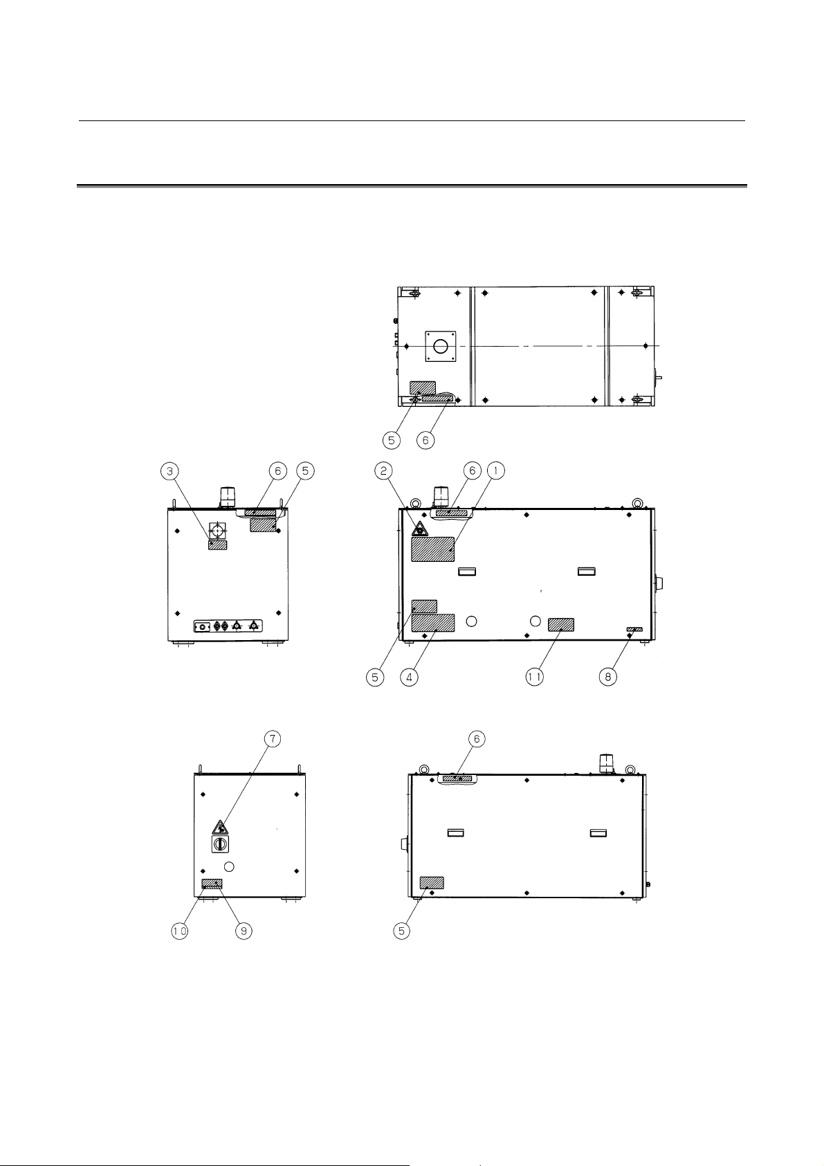
2.4 WARNING LABELS
The oscillator uses high voltages and laser beam radiation. Such
hazards are indicated with warning labels attached to the positions
shown in Fig. 2.4 (a) to (b).
Fig. 2.4 (a) Warning label positions (C1000iA : front view)
Fig. 2.4 (a) Warning label positions (C1000iA : rear view)
- 12 -
B-70255EN/01 2.SAFETY
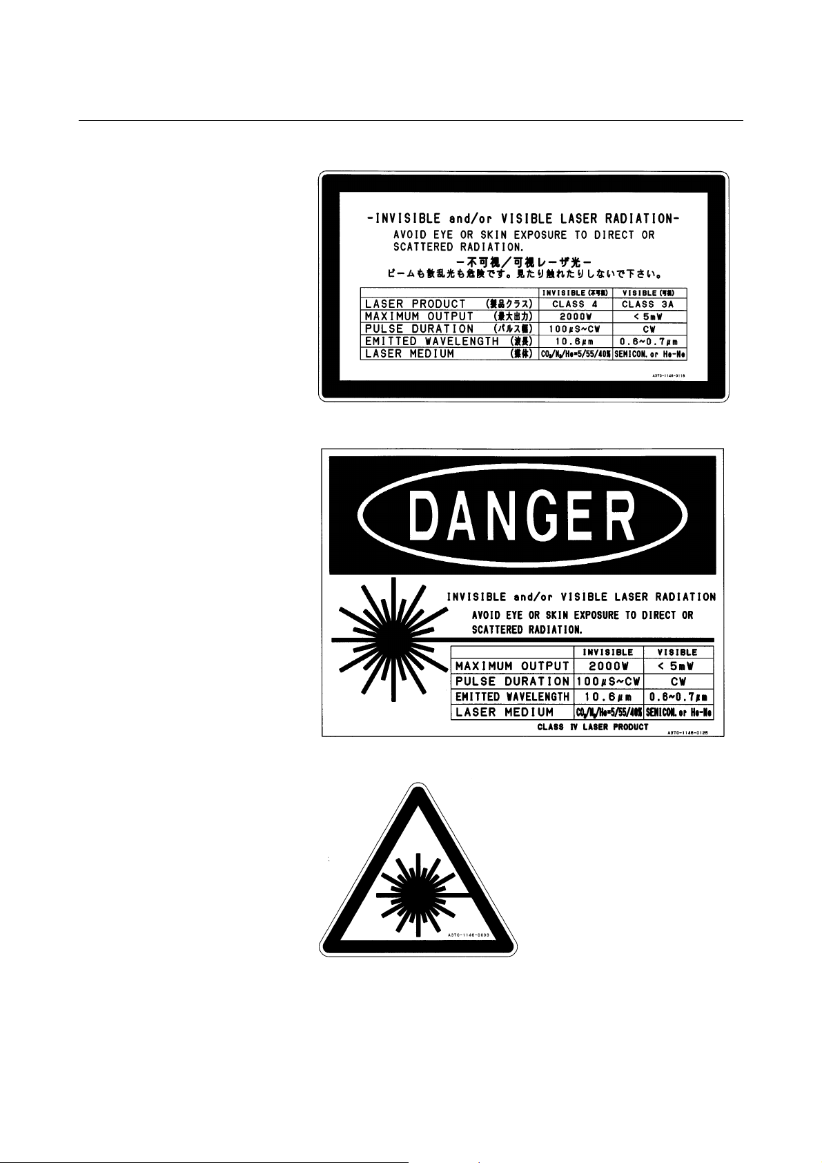
(1) Class indication label (JPN)
(1) Class indication label (FDA)
(2) Warning label
- 13 -
2.SAFETY B-70255EN/01
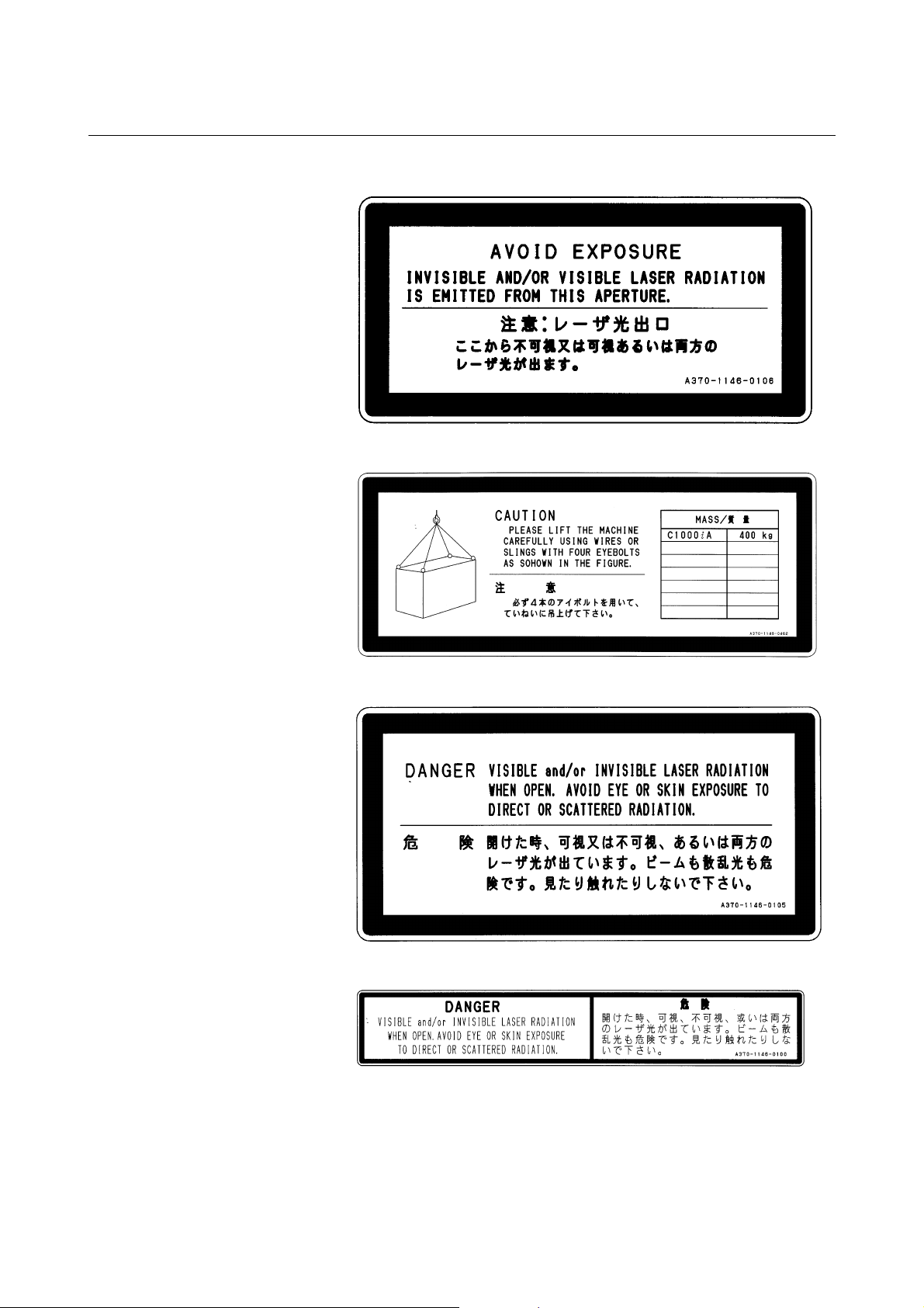
(3) Aperture label
(4) Suspension method label
(5) Access panel
(6) Label inside the access panel
- 14 -
B-70255EN/01 2.SAFETY
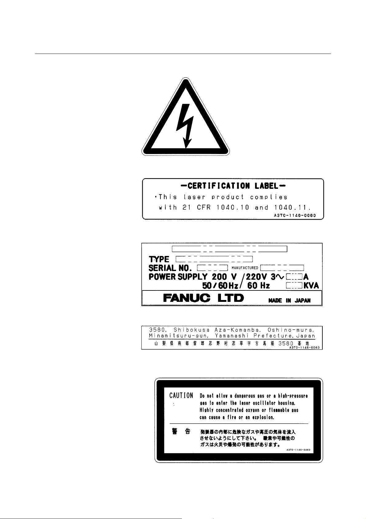
(7) Discharge section label
(8) Certification label
(9) Equipment nameplate
(10) Manufacturer's address label
(11) Label for regulating the atmospheric gases in the oscillator
housing
- 15 -
2.SAFETY B-70255EN/01
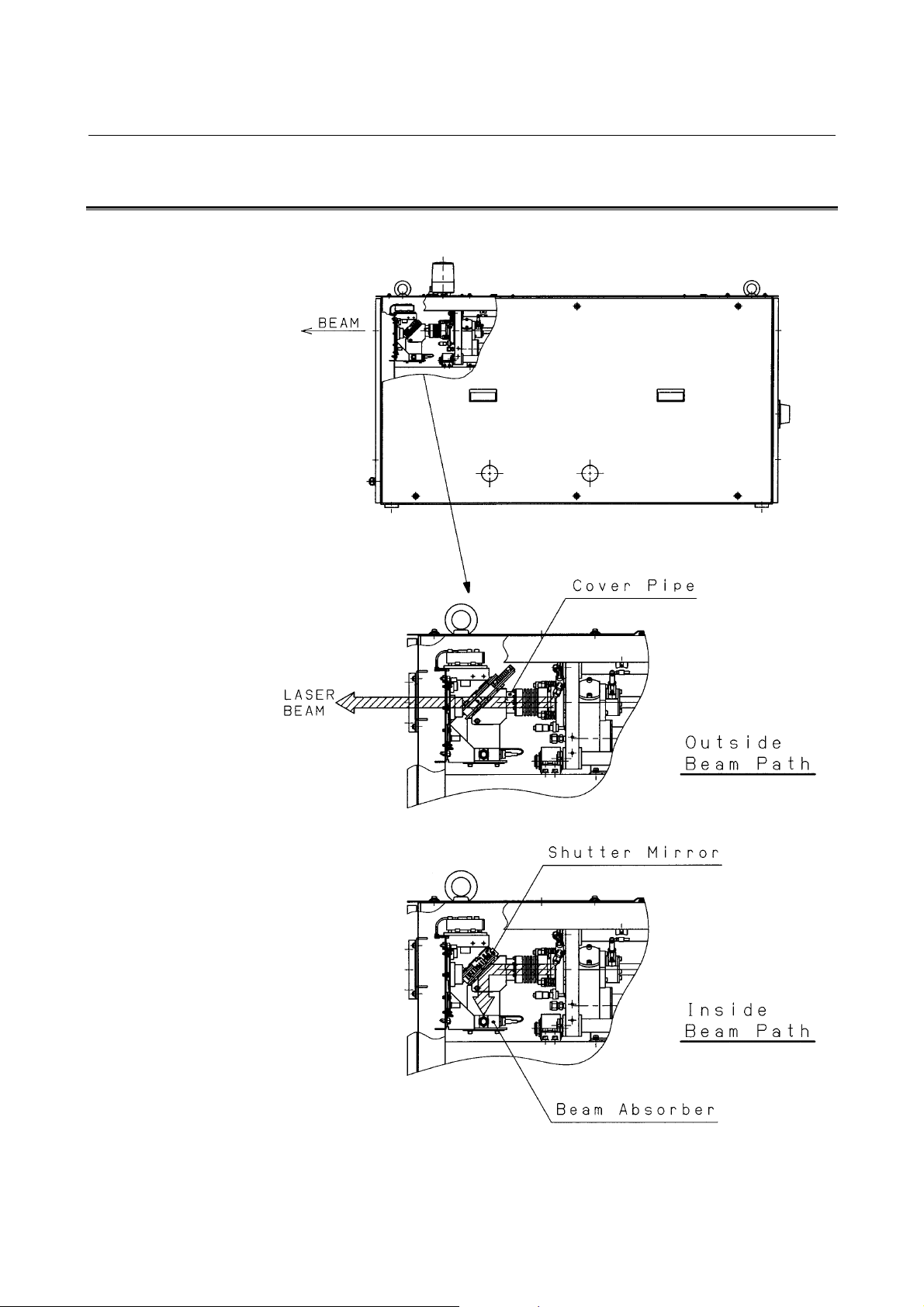
2.5 OPTICAL PATHS IN THE OSCILLATOR
The figures below show the laser optical paths inside the oscillator.
Fig.2.5(a) Optical paths in the C1000iA
- 16 -

B-70255EN/01 3.INTERNAL STRUCTURE
3 INTERNAL STRUCTURE
- 17 -
3.INTERNAL STRUCTURE B-70255EN/01
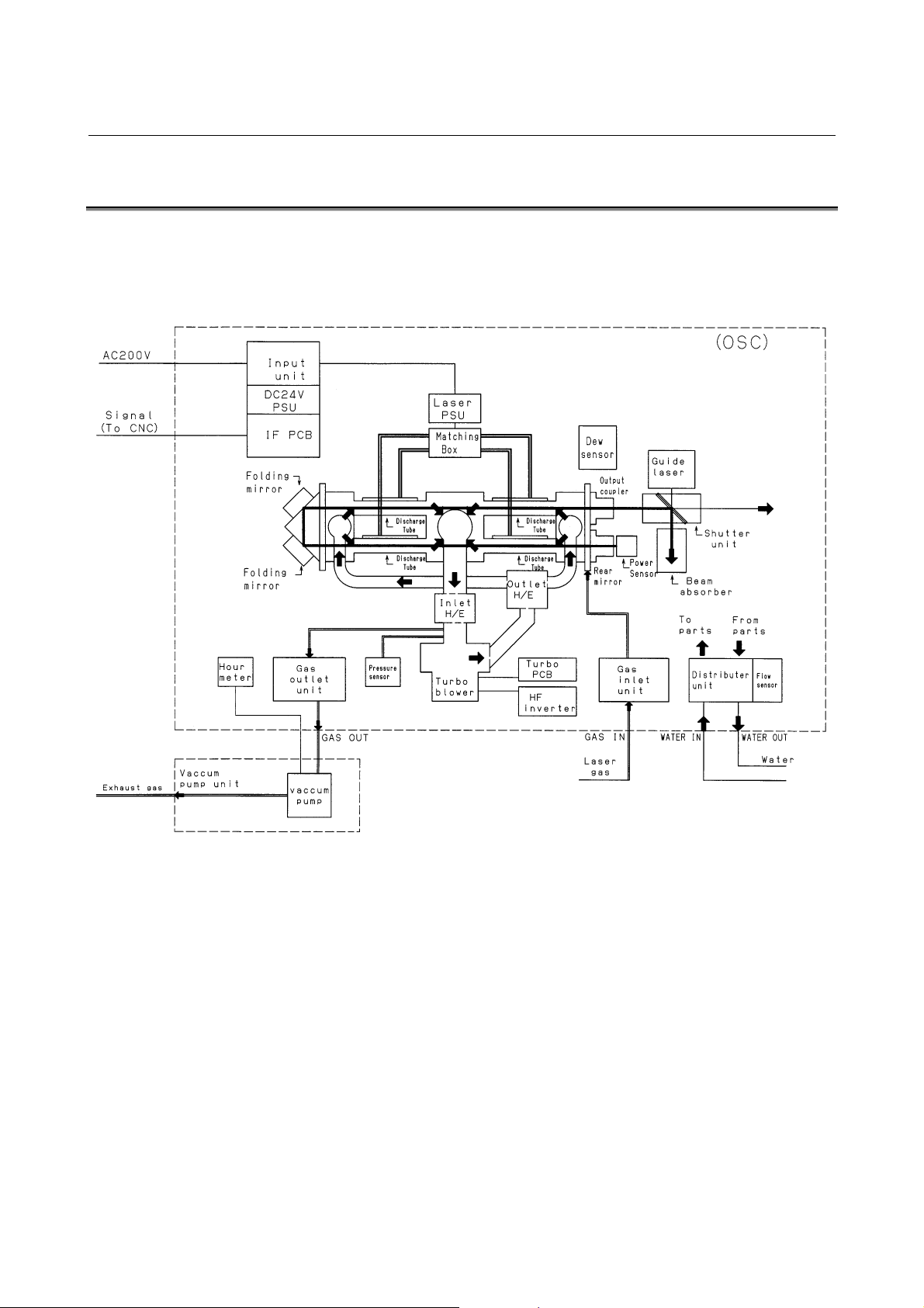
3.1 OUTLINE
Fig. 3.1 show the internal structure of the laser oscillator.
The C1000iA consists of a laser resonator, discharge drive unit,
forced gas circulating system, pressure controller, CNC interface, and
a protective housing.
Fig. 3.1 C1000iA internal structure
(1) Laser resonator
The laser resonator consists of several discharge tubes,
connected in series using folding mirrors, with a rear mirror and
output mirror placed at the open ends of the discharge tubes, thus
sealing the tubes. The resonator is fitted with a gas pipe
connecting port through which laser gas is fed into the discharge
tubes.
A discharge from the electrodes of the discharge tube energizes
CO
molecules, which emit light. This light is amplified by
2
stimulated emission, repeated between the rear mirror and output
mirror, a laser beam being emitted from the output mirror.
- 18 -

B-70255EN/01 3.INTERNAL STRUCTURE
(2) Discharge drive unit
The discharge drive unit consists of a laser power supply,
matching box, and discharge tubes. High-frequency output of 2
MHz that is controlled by the CNC discharges the laser gas
flows through discharge tubes to energize CO
molecules.
2
(3) Forced gas circulating system
A gas circulating system is configured by connecting the
resonator and turbo blower with a circulating pipe. Laser gas is
forced through the discharge tubes at a speed of 200 m/s or
higher.
A water-cooled heat exchanger, used to cool the hightemperature gas from the discharge tubes, is provided at the inlet
side of the turbo blower. At the outlet side of the turbo blower,
another water-cooled heat exchanger dissipates the compression
heat.
(4) Pressure controller
The laser gas pressure within the forced gas circulating system is
controlled by commands issued from the CNC, thus ensuring
stable laser output.
(5) CNC interface
Interface used to connect a FANUC Series 16i-L. CNC
commands that, control the operation of the laser oscillator, such
as start/stop and laser output, are input via this interface.
(6) Protective housing
An enclosure that houses the above components. The housing,
consisting of metal panels, completely encloses the laser
oscillator, thus protecting the operator from exposure to laser
radiation and from high voltages. All panels are screw-fixed and
cannot be removed without an appropriate tool.
- 19 -
3.INTERNAL STRUCTURE B-70255EN/01
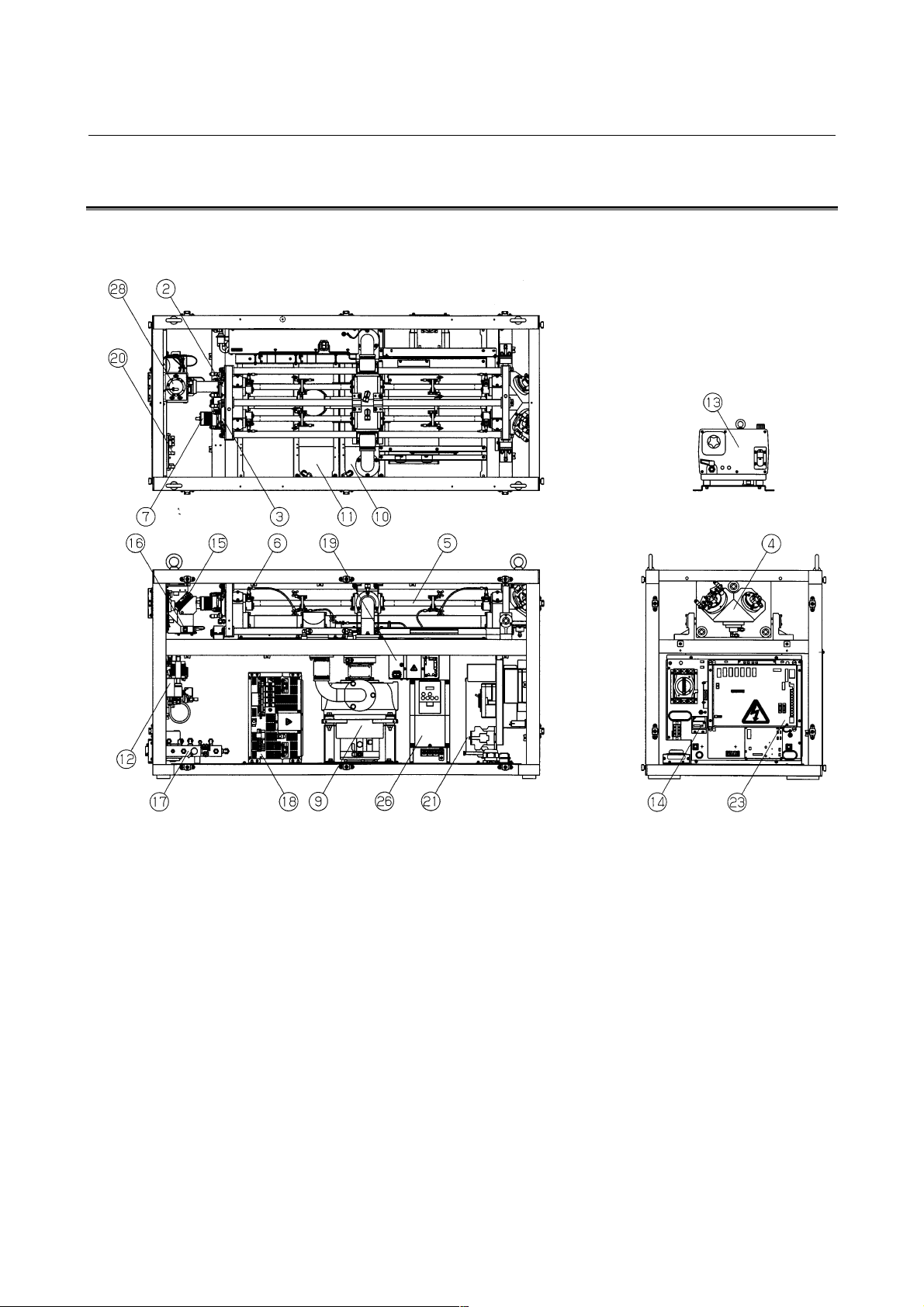
3.2 COMPONENT DETAILS
This section describes the internal structure of the C1000iA more
specifically. Fig. 3.2 is an internal structural drawing.
Fig. 3.2 C1000iA structural drawing
(1) Resonator
The resonator consists of an output mirror, rear mirror, folding
mirrors, discharge tubes, power sensor unit, etc. It converts
electrical energy first to laser gas, then to optical energy (10.6mm single-wavelength laser beam).
(2) Output mirror
A transmitting/reflecting mirror which outputs the laser beam
after it has been amplified. The output mirror consists of a ZnSe
(zinc selenide) substrate, coated with dielectric. ZnSe is tightly
toxic. Be particularly careful, therefore, when handling the
output mirror.
- 20 -

B-70255EN/01 3.INTERNAL STRUCTURE
(3) Rear mirror
A reflecting mirror consisting of a Ge (germanium) substrate,
coated with dielectric.
Having a high reflectance of 99.5%, the rear mirror is used to
reflect the laser beam within the resonator while transmitting
0.5% of the laser light so that the beam can be monitored
externally.
(4) Folding mirror
A mirror unit which reflects the laser beam at a 90-degree angle.
The folding mirror consists of a block with a surface tilting to a
45-degree angle and an Si (silicon) substrate, coated with
multilayer dielectric film.
(5) Discharge tube
A pair of Ag (silver) electrodes are metallized on the surface of a
hollow quartz glass pipe. A high-frequency discharge between
these electrodes injects electrical energy into the laser gas. Each
electrode is coated with ceramic, preventing it from degrading
and thus improving system reliability.
(6) Trigger electrode
A predischarge placed outside the laser oscillation area can
facilitate the start of the main discharge. With it, the laser output
is completely zero when the beam is off.
(7) Power sensor
An optical sensor which detects the intensity of the laser beam,
transmitted through the rear mirror, thus enabling monitoring of
the laser output level.
(8) Gas circulating system
A gas circulating path including a turbo blower, heat exchangers,
and circulating pipes, which circulates laser gas in the discharge
tubes at high speed.
(9) Turbo blower
During laser oscillation, the laser gas pressure is 1330 – 9310 Pa.
The turbo blower circulates this rough-vacuum gas at high speed
without contaminating the gas.
(10) Heat exchanger (inlet)
Water-cooled heat exchanger used to cool the laser gas that has
been heated by discharge, before it is drawn into the turbo
blower.
(11) Heat exchanger (outlet)
Water-cooled heat exchanger used to cool the laser gas that has
been heated by compression in the turbo blower, before being
forced into the discharge tubes.
- 21 -

3.INTERNAL STRUCTURE B-70255EN/01
(12) Gas controller
The gas controller always monitors the gas pressure in each
discharge tube and supplies the fresh laser gas to the circulating
system to keep the pressure constant. It also monitors the supply
status of the laser gas, purge check for the circulating system,
and other items and has a function of adjusting the amount of
flow of the gas to be exhausted.
(13) Exhaust pump unit
This unit is used to vacuum-exhaust laser gas from the gas
circulating system such that its pressure falls to that used for
laser oscillation. Also, within this unit, a small amount of
circulating gas is constantly being exchanged, to prevent
degradation of the circulating gas.
(14) Hour meter
The hour meter indicates the total number of hours that the laser
oscillator has operated (how many hours the exhaust pump has
operated), to indicate whether maintenance or inspection is
necessary.
(15) Shutter
The shutter has a rotary arm operated by a rotary solenoid and an
Au (gold)-evaporated reflecting mirror attached to the arm.
It can be opened and closed by CNC commands. It also has a
position sensor and a temperature sensor for safety and always
monitors the open/close status and shutter temperature.
(16) Beam absorber
While the laser oscillator is operating with the shutter closed, the
laser beam is guided into the beam absorber. The beam absorber
absorbs nearly 100% of laser beam and is water-cooled, allowing
it to safely absorb the beam for relatively long periods. For
safety, the beam absorber is equipped with a temperature sensor
which allows the system to monitor the temperature of the beam
absorber.
(17) Distribution unit
This unit distributes cooling water, supplied from either a chiller
unit or a temperature-regulated external water supply, to each
unit in the laser oscillator.
For safety, the water distribution unit is equipped with a flow
sensor which allows the system to monitor the flow rate of the
cooling water.
(18) Laser power supply
A power supply for generating a discharge in each discharge
tube. The laser power supply receives the three-phase AC input
at 200/220V and outputs 2-MHz high-frequency power
controlled with stability by commands from the CNC.
- 22 -

B-70255EN/01 3.INTERNAL STRUCTURE
(19) Matching box
The matching box contains a matching circuit, consisting of coils
and capacitors, which ensures that power is effectively input to
the discharge tubes.
(20) Intermediate PCB B
This PCB transmits signals output by the shutter section, such as
those from the limit switch, absorber temperature sensor, power
sensor, and condensation sensor, to the interface PCB.
(21) Input unit
The power magnetics cabinet distributes power, supplied from
an external unit, to each unit in the laser oscillator. It also
protects each unit from overcurrents.
(22) Input unit control PCB
This PCB has functions of transmitting the contactor open/close
signals according to CNC commands and of notifying the CNC
of the open/close status of the circuit breaker in the input unit.
(23) Interface PCB
Transfers signals to and from the CNC via the FANUC I/O Link
(serial interface).
(24) Stabilized power supply
This unit converts the 200/220 VAC power source to DC power
for the interface PCB and other units.
(25) Condensation sensor
The condensation sensor is mounted above the output mirror
holder. If condensation occurs on this sensor, the resistance
changes, an alarm (abnormal water temperature) occurs, and the
oscillator is stopped. It prevents faults in each unit from
occurring due to condensation.
(26) High-frequency inverter
This inverter drives the turbo blower. It is responsible for
acceleration/deceleration control during start and stop of the
blower.
(27) Turbo PCB
This PCB monitors overheating, the oil level, and frequency
reached signal of the turbo blower.
(28) Guide laser (diode laser)
A diode laser is overlaid on the same optical axis as a guide
beam for checking the optical axis because the CO
laser beam is
2
invisible to the unaided eye. The guide beam is emitted in
synchronization with the mechanical shutter only when the
shutter is closed. The guide laser can be used for roughly
- 23 -
 Loading...