


Instruction Sheet
PN 51A-5081T-FF/FI/rev.A
November 2005
Model 5081T-FF/FI
FOUNDATION Fieldbus® Two-Wire
Conductivity Transmitter
For additional information, please refer to the Instruction Manuals CD shipped with this product, or visit our website at www.emersonprocess.com/raihome/liquid/.
ESSENTIAL INSTRUCTIONS
READ THIS PAGE BEFORE PROCEEDING!
Your purchase from Rosemount Analytical, Inc. has result- |
• For clarification of instructions, contact your Rosemount |
|
ed in one of the finest instruments available for your par- |
representative. |
|
ticular application. These instruments have been |
• Follow all warnings, cautions, and instructions marked |
|
designed, and tested to meet many national and interna- |
on and supplied with the product. |
|
tional standards. Experience indicates that its perform- |
• Use only qualified personnel to install, operate, update, |
|
ance is directly related to the quality of the installation and |
||
program and maintain the product. |
||
knowledge of the user in operating and maintaining the |
||
• Educate your personnel in the proper installation, oper- |
||
instrument. To ensure their continued operation to the |
||
ation, and maintenance of the product. |
||
design specifications, personnel should read this manual |
||
• Install equipment as specified in the Installation section |
||
thoroughly before proceeding with installation, commis- |
||
sioning, operation, and maintenance of this instrument. If |
of this manual. Follow appropriate local and national |
|
this equipment is used in a manner not specified by the |
codes. Only connect the product to electrical and pres- |
|
manufacturer, the protection provided by it against haz- |
sure sources specified in this manual. |
|
ards may be impaired. |
• Use only factory documented components for repair. |
|
• Failure to follow the proper instructions may cause any |
Tampering or unauthorized substitution of parts and |
|
one of the following situations to occur: Loss of life; per- |
procedures can affect the performance and cause |
|
sonal injury; property damage; damage to this instru- |
unsafe operation of your process. |
|
ment; and warranty invalidation. |
• All equipment doors must be closed and protective cov- |
|
• Ensure that you have received the correct model and |
ers must be in place unless qualified personnel are per- |
|
options from your purchase order. Verify that this manu- |
forming maintenance. |
|
al covers your model and options. If not, call 1-800- |
• If this equipment is used in a manner not specified by |
|
854-8257 or 949-757-8500 to request correct manual. |
the manufacturer, the protection provided by it against |
|
|
hazards may be impaired. |
 WARNING
Substitution of components may impair Intrinsic Safety or suitability for Division 2.
 WARNING
Do not remove or replace while circuit is live unless area is known to be non-hazardous.
WARNING
To prevent ignition of flammable or combustible atmospheres, disconnect power before servicing or understand and adhere to the manufacturer's live maintenance procedures.
 WARNING
Explosion Hazard - Do not disconnect equipment unless area is known to be non-hazardous.

MODEL 5081T-FF/FI |
SPECIFICATIONS |
PHYSICAL SPECIFICATIONS
HOUSING: Epoxy-polyester painted over low-copper aluminum. Neoprene O-rings on cover. 160.5 mm x 175.3 mm x 161.3 mm (6.3 in. x 6.9 in. x 6.4 in.)
DIAMETER: 155.4 mm (6.1 in.)
ELECTRICAL CONDUIT OPENINGS: 3/4 in. FNPT
POWER SUPPLY AND LOAD: A power supply voltage of 9 Vdc to 32 Vdc at 22 mA is required; Intrinsically Safe installations may be limited to a maximum of 2-3 transmitters per node, depending on the barrier used.
LOCAL READOUT:
Main Display is 4 digits, 20 mm tall (0.8 in.) Message Display is ten digits, 7 mm tall (0.3 in.)
AUTOMATIC TEMPERATURE COMPENSATION:
3-wire Pt100 RTD
Conductivity: 0 to 200 °C (32 to 392 °F) % concentration: 0 to 100 °C (32 to 212°F)
AMBIENT TEMPERATURE: -20 to 65° C (-4 to 149° F)
RELATIVE HUMIDITY: 0-95% with enclosure sealed.
CE: EMI/RFI certified: EN61326-1 
HAZARDOUS AREA CLASSIFICATION: Intrinsic Safety:
Class I, II, III, Div. 1 Groups A-G
T4 Tamb = 70°C
Exia Entity
Class I, Groups A-D
Class II, Groups E-G
Class III
T4 Tamb = 70°C
ATEX  0600
0600
II 1 G
Baseefa03ATEX0399 EEx ia IIC T4
Tamb = -20°C to +65°C
Non-Incendive:
Class I, Div. 2, Groups A-D
Dust Ignition Proof
Class II & III, Div. 1, Groups E-G
NEMA 4X Enclosure
Class I, Div. 2, Groups A-D
Suitable for Class II, Div. 2, Groups E-G
T4 Tamb = 70°C
Explosion-Proof:
Class I, Div. 1, Groups B-D
Class II, Div. 1, Groups E-G
Class III, Div. 1
Class I, Groups B-D
Class II, Groups E-G
Class III
Tamb = 65°C max
TRANSMITTER SPECIFICATIONS @ 25°C
MEASURED RANGE*: 50 to 2,000,000 µS/cm (see chart)
ACCURACY: ± 1.0% of reading
REPEATABILITY: ± 0.25% of reading
STABILITY: 0.25% of output range/month, non-cumulative
AMBIENT TEMPERATURE COEFFICIENT: ± 0.2% of FS/°C
COMPATIBLE RTD: 100Ω with Automatic Recognition
TEMPERATURE SLOPE ADJUSTMENT: 0-5%/° C
%CONCENTRATION RANGES:
Sodium Hydroxide: 0 to 15% Hydrochloric Acid: 0 to 16%
Sulfuric Acid: 0 to 25% and 96 to 99.7%
LOOP SPECIFICATIONS
LOOP ACCURACY: With a standard Model 228 or 225 sensor with 20' cable, laboratory accuracy at 25°C can be as good as ±2% of reading and ±50 µS/cm.
To achieve optimum performance, standardize the sensor in the process at the conductivity and temperature of interest.
Results under real process conditions, at different temperatures, or using other sensors may differ from above.
RTD ACCURACY: Utilizing a perfect 100 Ohm RTD after 1 point temperature standardiztion, temperature reading can be as good as ±0.5°C.
RECOMMENDED SENSORS:
Model 222 Flow-Through
Model 225 Clean-In-Place (CIP)
Model 226 Submersion/Insertion
Model 228 Submersion/Insertion/Retractable
Model 242 Flow-Through*
*Model 242-06 or 242-08 with 5081T do not have Intrinsically Safe approvals.
RECOMMENDED RANGES FOR TOROIDAL SENSORS
|
Conductivity Sensor |
|
|
|
|
|
|
|
Model Number |
226 |
228 |
225 |
222 (1in.) |
222 (2 in.) |
242 |
|
|
|
|
|
|
|
|
|
Nominal Cell Constant |
1.0 |
3.0 |
3.0 |
6.0 |
4.0 |
* |
|
Minimum Conductivity (µS/cm) |
50 |
200 |
200 |
500 |
500 |
100* |
|
|
|
|
|
|
|
|
|
Maximum Conductivity (µS/cm) |
1,000,000 |
2,000,000 |
2,000,000 |
2,000,000 |
2,000,000 |
2,000,000* |
|
|
|
|
|
|
|
|
* Model 242 values depend on sensor configuration and wiring.
NOTE: Values shown are for 25°C conductivity with a temperature slope of 2% per degree C. The maximum range
2 |
value will be lower for solutions with a higher temperature slope. Minimum conductivity depends on sensor. |
|

MODEL 5081T-FF/FI
TRANSMITTER DISPLAY DURING CALIBRATION AND PROGRAMMING (FIGURE 1)
1.Continuous display of conductivity, % concentration, or custom reading.
2.Units: µS/cm, mS/cm, ppm, %, or none.
3.Current menu appears here.
4.Submenus, prompts, and diagnostic readings appear hear.
5.Commands available in each submenu or at each prompt appear here.
6.Hold appears when the transmitter is in hold.
7.Fault appears when the transmitter detects a sensor or instrument fault.
INFRARED REMOTE CONTROLLER (FIGURE 2)
1.Pressing a menu key allows the user access to calibrate, program, or diagnostic menus.
2.Press ENTER to store data and settings. Press NEXT to move from one submenu to the next. Press EXIT to leave without storing changes.
3.Use the editing keys to scroll through lists of allowed settings or to change a numerical setting to the desired value.
4.Pressing HOLD puts the transmitter in hold. Pressing RESET causes the transmitter to abandon the present operation and return to the main display.
SPECIFICATIONS
|
|
|
|
|
|
|
|
1 |
|
||
|
|
|
|
|
|
|
|
|
|
|
2 |
7 |
|
F |
|
|
|
|
|
|
|
|
|
|
A |
|
|
|
|
|
|
|
|
||
|
|
|
U |
#'" mS |
|
|
|
|
|||
|
|
|
H |
|
|
|
|
||||
|
|
|
L |
|
|
|
|
|
|
|
|
|
|
|
T |
|
|
|
|
|
|
|
|
|
|
|
O |
|
|
|
|
|
|
|
|
|
|
|
L |
|
|
|
|
|
|
|
|
6 |
|
D |
|
|
|
|
|
|
|
3 |
|
|
|
|
|
|
|
|
|
|
|||
|
|
|
CALIBRATE PROGRAM |
DIAGNOSE |
|
|
|
|
|||
|
|
|
|
|
|
|
|||||
|
|
|
|
/ - [ 5 E S - U 1 |
|
|
|
4 |
|||
|
|
|
|
|
|
||||||
|
|
|
|
|
|
|
|
||||
|
|
|
E X I T N E X T |
E N T E R |
|
||||||
|
|
|
|
||||||||
|
5 |
|
|
|
|
|
|
|
|
|
|
|
|
|
|
|
|
|
|
|
|||
|
|
|
|
|
|
|
|
|
|
|
|
FIGURE 1. TRANSMITTER DISPLAY DURING CALIBRATION AND PROGRAMMING
The program display screen allows access to calibration and programming menus.
4.
3.
1. 2.
FIGURE 2. INFRARED REMOTE CONTROLLER
IRC - INFRARED REMOTE CONTROL
REMOTE CONTROL |
LR 34186 |
SUBSTITUTION OF |
IS/I/1/A,B,C & D |
YEAR |
|
Exia |
COMPONENTS MAY |
NI/I/2/A,B,C & D |
|||
|
|||||
INTRINSICALLY SAFE EQUIPMENT |
IMPAIR INTRINSIC SAFETY |
T4 Tamb = 40°C |
|||
HAZARDOUS AREA LOCATIONS: |
PN 23572-00 |
T3A Tamb = 80°C |
|
||
|
|
||||
CLASS I, DIV 1, GP A, B, C, D |
|
|
|||
|
Baseefa02ATEX0198 |
|
|||
CLASS I, DIV 2, GP A, B, C, D |
|
|
|||
WARNING: |
II 1G EExia IIC T4 |
1180 |
|||
T3C Tamb = 40°C T3 Tamb = 80°C |
|||||
TO PREVENT IGNITION |
|||||
1.5Vdc AAA BATTERIES |
|||||
1.5Vdc AAA BATTERIES |
|
CHANGE BATTERIES IN |
EVEREADY E92/1212 |
|
|
EVEREADY E92/1212 |
|
A NONHAZARDOUS AREA |
DURACELL MN2400/PC2400 |
||
DURACELL MN2400/PC2400 |
ONLY |
ROSEMOUNT ANALYTICAL 92606 USA |
|||
3

MODEL 5081T-FF/FI MENU TREE
Model 5081T-FF/FI |
FIGURE 1. Menu Tree |
Process Display Screen |
|
'""" µS/cm CALIBRATION
25.0C 12.00mA
CAL key
PROG key
DIAG key
HOLD key
Process Display 

DIAGNOSTICS
/-[5ES-U1
<1P<9S!"
U17:!-G6
/1[[!/9P<U
U17:!<[9:1
U17:
G5<:[-A
G12->[=
-E< /!
922<U
/1[[!/9P<U
U<[9:1
'"*#\=\22
<Q2U
4-SG
2D>[=T
PROGRAM MENU MNEMONICS
4Q[G |
Transmitter on |
|
2->[U |
Fault condition |
|
U17: |
Temperature |
|
U->U9 |
Automatic |
|
U7-P |
Manual temperature |
input |
G5<:[-A |
Display menu |
|
UA: |
Conductivity |
|
U17:! |
°C / °F toggle |
|
/9G1 |
Security code |
|
922<U |
Conductance |
|
|
|
|
4
MODEL 5081T-FF/FI DEFAULT SETTINGS
VARIABLE NAME |
MNEMONIC |
FACTORY SETTINGS |
CUSTOMER SETTINGS |
Program Menu |
|
|
|
Temperature |
UHOR |
|
|
Auto temperature compensation |
UDVUQ |
on |
___________ |
Manual temperature |
UODP |
25.0°C (overridden by auto) |
___________ |
Temperature compensation algorithm |
/97: ([LPHDS or P9P1) |
LInEAr |
___________ |
Display |
GLTRNDY |
|
|
Measurement type |
UYR (/QPG>/ or P-94 or 4/[ |
CondUC |
___________ |
|
or 4$<9&[ or 4$<9&4 or /VTU) |
|
|
Temperature (°C or °F) |
UHOR |
C |
___________ |
Output (mA or %) |
QVURVU |
Cur |
___________ |
Security Code |
FQGH |
000 |
___________ |
Custom Curve |
<1U>:!/V<U |
|
___________ |
Reference temperature |
U!SHI |
25.0°C |
___________ |
Calibrate Menu |
|
|
|
Cell constant |
/1[[!/QPTU |
3.00 |
___________ |
Temperature slope |
U17:!TN9RH |
2.000 |
___________ |
Diagnose Menu |
|
|
|
Diagnose |
|
SAMPLE READINGS |
|
(Each segment displays the current value in the transmitter.) |
|
|
|
Absolute conductivity |
-ET |
1000 µS |
___________ |
Off Set |
9II<U |
0.0 µS |
___________ |
Cell constant |
/1[[!/9P<U |
3.00/cm |
___________ |
Temperature slope |
UTNQRH |
2.000 |
___________ |
Software version |
TQIU |
A02.09 |
___________ |
Hardware version |
4-SG |
01 |
___________ |
Show fault warnings |
2D>[=< |
none |
___________ |
|
|
|
|
5

MODEL 5081T-FF/FI |
WIRING |
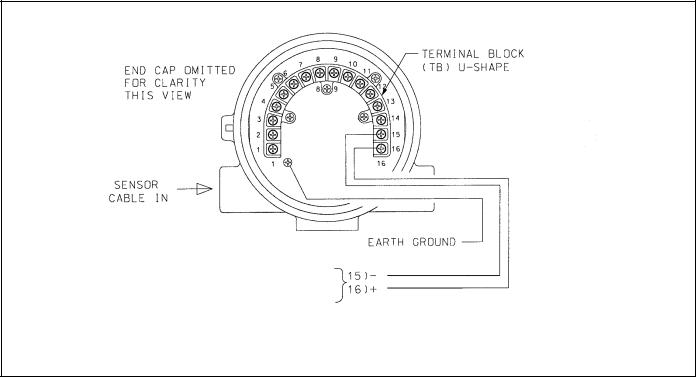
WIRING
Wire sensor as shown below in Figure 2. Keep sensor wiring separate from power wiring. For best EMI/RFI protection, use shielded output signal cable in an earth-grounded metal conduit. Refer to the sensor instruction manual for more details.
FIGURE 2. Wiring Model 5081T-FF/FI
6
MODEL 5081T-FF/FI |
WIRING |
FOUNDATION FIELDBUS COMMUNICATIONS AND POWER SUPPLY
9 - 32 VDC
FIGURE 3. Power Supply/Current Loop Wiring for Model 5081T-FF/FI
WIRING THROUGH A JUNCTION BOX
The sensor can be wired to the analyzer through a remote junction box (PN 23550-00). Wire the extension cable and sensor cable point-to-point. Refer to the sensor instruction manual for more details.
Factory-terminated (PN 23747-00) and unterminated (PN 9200275) connecting cable are available. The use of fac- tory-terminated cable is strongly recommended. To prepare unterminated cable for use, follow the instructions in the sensor instruction manual.
For maximum EMI/RFI protection, the outer braid of the sensor cable should be connected to the outer braided shield of the extension cable. At the instrument, connect the outer braid of the extension cable to earth ground.
POWER WIRING
For general purpose areas, wire power as shown in Figure 3.
7

MODEL 5081T-FF/FI |
INSTALLATION |
INSTALLATION
UNPACKING AND INSPECTION
Inspect the shipping container. If it is damaged, contact the shipper immediately for instructions. Save the box. If there is no apparent damage, unpack the container. Be sure all items shown on the packing list are present. If items are missing, notify Rosemount Analytical immediately.
ROTATING THE DISPLAY
The Model 5081T-FF/F1 display can be rotated 90° left or right. Disengage the cover lock and remove the front cover. Remove the three screws holding the PCB stack and gently lift the display board. Do not disengage the ribbon cable between the display board and the CPU board. Rotate the display. The black infrared sensor will be at the top of the display.
INSTALLATION
See Figure 4.
1.Although the analyzer is suitable for outdoor use, do not install it in direct sunlight or in areas of extreme temperatures.
2.Install the analyzer in an area where vibrations and electromagnetic and radio frequency interference are minimized or absent.
3.Keep the analyzer and sensor wiring at least one foot from high voltage conductors. Be sure there is easy access to the analyzer.
4.The conduit connections on the sides of the 5081 housing should be sealed to prevent moisture from entering the enclosure.
5.The transmitter must not be mounted with both conduit openings at the top.
INCH |
MILLIMETER |
FIGURE 4. Mounting Model 5081T-FF/FI
8
 Loading...