


 Loading...
Instruction Manual
IB-106-5081, Rev. 1.0
May 2005
Model 5081FG
Two-Wire In Situ Oxygen Analyzer (550° to 1600°C)
http://www.raihome.com

ESSENTIAL INSTRUCTIONS
READ THIS PAGE BEFORE PROCEEDING!
Rosemount Analytical designs, manufactures and tests its products to meet many national and international standards. Because these instruments are sophisticated technical products, you MUST properly install, use, and maintain them to ensure they continue to operate within their normal specifications. The following instructions MUST be adhered to and integrated into your safety program when installing, using, and maintaining Rosemount Analytical products. Failure to follow the proper instructions may cause any one of the following situations to occur: Loss of life; personal injury; property damage; damage to this instrument; and warranty invalidation.
•Read all instructions prior to installing, operating, and servicing the product.
•If you do not understand any of the instructions, contact your Rosemount Analytical representative for clarification.
•Follow all warnings, cautions, and instructions marked on and supplied with the product.
•Inform and educate your personnel in the proper installation, operation, and maintenance of the product.
•Install your equipment as specified in the Installation Instructions of the appropriate Instruction Manual and per applicable local and national codes. Connect all products to the proper electrical and pressure sources.
•To ensure proper performance, use qualified personnel to install, operate, update, program, and maintain the product.
•When replacement parts are required, ensure that qualified people use replacement parts specified by Rosemount Analytical. Unauthorized parts and procedures can affect the product’s performance, place the safe operation of your process at risk, and VOID YOUR WARRANTY. Look-alike substitutions may result in fire, electrical hazards, or improper operation.
•Ensure that all equipment doors are closed and protective covers are in place, except when maintenance is being performed by qualified persons, to prevent electrical shock and personal injury.
The information contained in this document is subject to change without notice.
Emerson Process Management
Rosemount Analytical Inc. Process Analytic Division
6565P Davis Industrial Parkway Solon, OH 44139
T (440) 914 1261
F (440) 914 1271
E gas.csc@emersonprocess.com
http://www.raihome.com
|
HIGHLIGHTS OF CHANGES |
|
Effective May, 2005 Rev. 1.0 |
|
|
Page |
Summary |
|
|
Throughout |
Changed IB revision number and release date. |
Cover |
Changed E-mail address. |
Inside Cover |
Changed mailing and E-mail addresses. |
Page 7-1 |
Changed repair facility address. |
Page 8-1 |
Changed Figure 5-1, item 10 part number in Table 8-1. |
|
|

Model 5081FG
Instruction Manual
IB-106-5081, Rev. 1.0
May 2005
TABLE OF CONTENTS
|
PREFACE........................................................................................................................ |
P-1 |
|
|
Definitions........................................................................................................................ |
P-1 |
|
|
Safety Instructions .......................................................................................................... |
P-2 |
|
1-0 |
DESCRIPTION AND SPECIFICATIONS........................................................................ |
1-1 |
|
1-1 |
Component Checklist Of Typical System (Package Contents) .................................. |
1-1 |
|
1-2 |
System Overview............................................................................................................ |
1-3 |
|
1-3 |
Specifications .................................................................................................................. |
1-7 |
|
2-0 |
INSTALLATION .............................................................................................................. |
2-1 |
|
2-1 |
Pre-Installation................................................................................................................. |
2-1 |
|
2-2 |
Mechanical Installation ................................................................................................... |
2-1 |
|
2-3 |
Electrical Installation....................................................................................................... |
2-9 |
|
2-4 |
Pneumatic Installation .................................................................................................. |
2-11 |
|
3-0 |
STARTUP AND OPERATION ...................................................................................... |
3-1 |
|
3-1 |
General............................................................................................................................ |
3-1 |
|
3-2 |
Power Up........................................................................................................................ |
3-1 |
|
3-3 |
Reestablishing Proper Calibration Check Gas Flow Rate......................................... |
3-2 |
|
3-4 |
Operation......................................................................................................................... |
3-3 |
|
3-5 |
Program Menu................................................................................................................ |
3-6 |
|
3-6 |
Diagnostics Menu ......................................................................................................... |
3-11 |
|
3-7 |
CALCHECK MENU ...................................................................................................... |
3-13 |
|
4-0 |
HART/AMS...................................................................................................................... |
4-1 |
|
4-1 |
Overview.......................................................................................................................... |
4-1 |
|
4-2 |
HART Communicator Signal Line Connections ........................................................... |
4-1 |
|
4-3 |
HART Communicator PC Connections ........................................................................ |
4-3 |
|
4-4 |
Off-Line and On-Line Operations ................................................................................. |
4-3 |
|
4-5 |
Menu Tree for HART Communicator/ |
|
|
|
Two-Wire In Situ Oxygen Analyzer Applications...................................................... |
4-3 |
|
4-6 |
HART Communicator Start CALCHECK Method........................................................ |
4-7 |
|
5-0 |
MAINTENANCE AND SERVICE .................................................................................. |
5-1 |
|
5-1 |
Model 5081 Electronics Replacement......................................................................... |
5-1 |
|
5-2 |
Oxygen Probe Replacement ......................................................................................... |
5-3 |
|
6-0 |
TROUBLESHOOTING .................................................................................................... |
6-1 |
|
6-1 |
General............................................................................................................................ |
6-1 |
|
6-2 |
Probe |
Life ....................................................................................................................... |
6-1 |
6-3 |
Fault |
Indications ............................................................................................................. |
6-2 |
6-4 |
Identifying and Correcting Fault Indications ................................................................. |
6-3 |
|
7-0 |
RETURN OF MATERIAL .............................................................................................. |
7-1 |
|
8-0 |
REPLACEMENT PARTS............................................................................................... |
8-1 |
|
9-0 |
INDEX.............................................................................................................................. |
9-1 |
|
Rosemount Analytical Inc. A Division of Emerson Process Management |
i |

Instruction Manual
IB-106-5081, Rev. 1.0
May 2005
Model 5081FG
LIST OF ILLUSTRATIONS
Figure 1-1. |
Typical System Package ....................................................................................... |
1-1 |
Figure 1-2. |
Two-Wire In Situ Oxygen Analyzer HART Connections and AMS Application ..... |
1-5 |
Figure 1-3. |
Typical System Installation .................................................................................... |
1-6 |
Figure 1-4. |
Power Supply and Load Requirements ................................................................. |
1-8 |
Figure 2-1. |
Probe Installation Details ....................................................................................... |
2-2 |
Figure 2-2. |
Optional Adapter Plate........................................................................................... |
2-3 |
Figure 2-3. |
Optional Probe Mounting Flange........................................................................... |
2-3 |
Figure 2-4. |
Horizontal Probe Installation.................................................................................. |
2-4 |
Figure 2-5. |
Adjusting Probe Insertion Depth............................................................................ |
2-5 |
Figure 2-6. |
Flat Surface Mounting Dimensional Information.................................................... |
2-7 |
Figure 2-7. |
Pipe Mounting Dimensional Information................................................................ |
2-8 |
Figure 2-8. |
Display Positioning Assembly................................................................................ |
2-9 |
Figure 2-9. |
Oxygen Probe Terminal Block............................................................................. |
2-10 |
Figure 2-10. |
Model 5081 Transmitter Terminal Block.............................................................. |
2-11 |
Figure 2-11. |
Oxygen Probe Gas Connections ......................................................................... |
2-11 |
Figure 2-12. |
Air Set, Plant Air Connection ............................................................................... |
2-12 |
Figure 3-1. |
Normal Operation Display...................................................................................... |
3-1 |
Figure 3-2. |
Faulted Operation Display ..................................................................................... |
3-1 |
Figure 3-3. |
Proper Calibration Check Gas Flow Rate.............................................................. |
3-2 |
Figure 3-4. |
Normal Operation Display...................................................................................... |
3-3 |
Figure 3-5. |
Model 5081 Transmitter Menu Tree ...................................................................... |
3-4 |
Figure 3-6. |
Infrared Remote Control (IRC)............................................................................... |
3-5 |
Figure 3-7. |
CODE..................................................................................................................... |
3-6 |
Figure 3-8. |
DISPLAY CODE ................................................................................................... |
3-6 |
Figure 3-9. |
FAULT VAL........................................................................................................... |
3-7 |
Figure 3-10. |
UPPER RANGE VAL........................................................................................... |
3-7 |
Figure 3-11. |
CELL T HI ............................................................................................................ |
3-7 |
Figure 3-12. |
RESET MAX CELL T........................................................................................... |
3-8 |
Figure 3-13. |
SET O2 FILTER TIME.......................................................................................... |
3-8 |
Figure 3-14. |
TRIM 4 mA?........................................................................................................... |
3-8 |
Figure 3-15. |
TRIM 20 mA?......................................................................................................... |
3-9 |
Figure 3-16. |
SET HI BOTTLE O2 ............................................................................................. |
3-9 |
Figure 3-17. |
SET LO BOTTLE O2 ............................................................................................ |
3-9 |
Figure 3-18. |
SET O2 TRACKING ............................................................................................ |
3-10 |
Figure 3-19. |
SET CODE.......................................................................................................... |
3-10 |
Figure 3-20. |
SHOW FAULT .................................................................................................... |
3-11 |
Figure 3-21. |
T/C mV................................................................................................................. |
3-11 |
Figure 3-22. |
O2 CELL mV ....................................................................................................... |
3-11 |
Figure 3-23. |
CELL IMPEDANCE ............................................................................................ |
3-12 |
Figure 3-24. |
PREVIOUS SLOPE ............................................................................................ |
3-12 |
Figure 3-25. |
PREVIOUS CONSTANT .................................................................................... |
3-12 |
Figure 3-26. |
MAX CELL T...................................................................................................... |
3-13 |
Figure 3-27. |
IN MANUAL? ...................................................................................................... |
3-14 |
Figure 3-28. |
ACCEPT HIGH O2 .............................................................................................. |
3-14 |
Figure 3-29. |
ACCEPT LOW O2 ............................................................................................... |
3-15 |
Figure 3-30. |
SLOPE ................................................................................................................. |
3-15 |
Figure 3-31. |
CONSTANT ......................................................................................................... |
3-15 |
Figure 4-1. |
Signal Line Connections, > 250 Ohms Lead Resistance ...................................... |
4-2 |
Figure 4-2. |
Signal Line Connections, < 250 Ohms Lead Resistance ...................................... |
4-3 |
ii |
Rosemount Analytical Inc. A Division of Emerson Process Management |

Model 5081FG
Instruction Manual
IB-106-5081, Rev. 1.0
May 2005
Figure 4-3. |
Menu Tree for HART/AMS on the Two-Wire In Situ |
|
|
Oxygen Analyzer (Sheet 1 of 3)............................................................................. |
4-4 |
Figure 5-1. |
Two-Wire In Situ Oxygen Analyzer Exploded View............................................... |
5-2 |
Figure 5-2. |
Oxygen Probe Terminal Block............................................................................... |
5-4 |
Figure 6-1. |
Slope vs. Impedance ............................................................................................. |
6-1 |
Figure 6-2. |
Speed of Response ............................................................................................... |
6-2 |
Figure 6-3. |
Faulted Operation Display ..................................................................................... |
6-2 |
Figure 6-4. |
Model 5081 Transmitter Terminal Block................................................................ |
6-3 |
Figure 6-5. |
Fault 1, Open Thermocouple................................................................................. |
6-4 |
Figure 6-6. |
Fault 2, Reversed Thermocouple .......................................................................... |
6-4 |
Figure 6-7. |
Fault 3, Shorted Thermocouple ............................................................................. |
6-5 |
Figure 6-8. |
Fault 4, High Probe Temperature .......................................................................... |
6-5 |
Figure 6-9. |
Fault 5, O2 Cell Open............................................................................................. |
6-6 |
Figure 6-10. |
Fault 6, Cell Impedance Too High ......................................................................... |
6-6 |
Figure 6-11. |
Fault 7, Reversed O2 Cell ...................................................................................... |
6-7 |
LIST OF TABLES
Table 1-1. |
Product Matrix........................................................................................................ |
1-2 |
Table 3-1. |
Model 5081 Transmitter Parameters ................................................................... |
3-10 |
Table 8-1. |
Replacement Parts List.......................................................................................... |
8-1 |
Rosemount Analytical Inc. A Division of Emerson Process Management |
iii |

Instruction Manual
IB-106-5081, Rev. 1.0
May 2005
Model 5081FG
iv |
Rosemount Analytical Inc. A Division of Emerson Process Management |
Model 5081FG
Instruction Manual
IB-106-5081, Rev. 1.0
May 2005
PREFACE
The purpose of this manual is to provide information concerning the components, functions, installation and maintenance of the Model 5081FG Two-Wire In Situ Oxygen Analyzer (550° to 1600°C).
Some sections may describe equipment not used in your configuration. The user should become thoroughly familiar with the operation of this module before operating it. Read this instruction manual completely.
DEFINITIONS
The following definitions apply to WARNINGS, CAUTIONS, and NOTES found throughout this publication.
Highlights an operation or maintenance procedure, practice, condition, statement, etc. If not strictly observed, could result in injury, death, or long-term health hazards of personnel.
Highlights an operation or maintenance procedure, practice, condition, statement, etc. If not strictly observed, could result in damage to or destruction of equipment, or loss of effectiveness.
NOTE
Highlights an essential operating procedure, condition, or statement.
: EARTH (GROUND) TERMINAL
: PROTECTIVE CONDUCTOR TERMINAL : RISK OF ELECTRICAL SHOCK
: WARNING: REFER TO INSTRUCTION BULLETIN
NOTE TO USERS
The number in the lower right corner of each illustration in this publication is a manual illustration number. It is not a part number, and is not related to the illustration in any technical manner.
Rosemount Analytical Inc. A Division of Emerson Process Management |
P-1 |
Instruction Manual
IB-106-5081, Rev. 1.0
May 2005
Model 5081FG
IMPORTANT
SAFETY INSTRUCTIONS
FOR THE WIRING AND INSTALLATION
OF THIS APPARATUS
The following safety instructions apply specifically to all EU member states. They should be strictly adhered to in order to assure compliance with the Low Voltage Directive. NonEU states should also comply with the following unless superseded by local or National Standards.
1.Adequate earth connections should be made to all earthing points, internal and external, where provided.
2.After installation or troubleshooting, all safety covers and safety grounds must be replaced. The integrity of all earth terminals must be maintained at all times.
3.Mains supply cords should comply with the requirements of IEC227 or IEC245.
4.All wiring shall be suitable for use in an ambient temperature of greater than 75°C.
5.All cable glands used should be of such internal dimensions as to provide adequate cable anchorage.
6.To ensure safe operation of this equipment, connection to the mains supply should only be made through a circuit breaker which will disconnect all circuits carrying conductors during a fault situation. The circuit breaker may also include a mechanically operated isolating switch. If not, then another means of disconnecting the equipment from the supply must be provided and clearly marked as such. Circuit breakers or switches must comply with a recognized standard such as IEC947. All wiring must conform with any local standards.
7.Where equipment or covers are marked with the symbol to the right, hazardous voltages are likely to be present beneath. These covers should only be removed when power is removed from the equipment — and then only by trained service personnel.
8.Where equipment or covers are marked with the symbol to the right, there is a danger from hot surfaces beneath. These covers should only be removed by trained service personnel when power is removed from the equipment. Certain surfaces may remain hot to the touch.
9.Where equipment or covers are marked with the symbol to the right, refer to the Operator Manual for instructions.
10.All graphical symbols used in this product are from one or more of the following standards: EN61010-1, IEC417, and ISO3864.
P-2 |
Rosemount Analytical Inc. A Division of Emerson Process Management |
Model 5081FG
Instruction Manual
IB-106-5081, Rev. 1.0
May 2005
BELANGRIJK
Veiligheidsvoorschriften voor de aansluiting en installatie van dit toestel.
De hierna volgende veiligheidsvoorschriften zijn vooral bedoeld voor de EU lidstaten. Hier moet aan gehouden worden om de onderworpenheid aan de Laag Spannings Richtlijn (Low Voltage Directive) te verzekeren. Niet EU staten zouden deze richtlijnen moeten volgen tenzij zij reeds achterhaald zouden zijn door plaatselijke of nationale voorschriften.
1.Degelijke aardingsaansluitingen moeten gemaakt worden naar alle voorziene aardpunten, intern en extern.
2.Na installatie of controle moeten alle veiligheidsdeksels en -aardingen terug geplaatst worden. Ten alle tijde moet de betrouwbaarheid van de aarding behouden blijven.
3.Voedingskabels moeten onderworpen zijn aan de IEC227 of de IEC245 voorschriften.
4.Alle bekabeling moet geschikt zijn voor het gebruik in omgevingstemperaturen, hoger dan 75°C.
5.Alle wartels moeten zo gedimensioneerd zijn dat een degelijke kabel bevestiging verzekerd is.
6.Om de veilige werking van dit toestel te verzekeren, moet de voeding door een stroomonderbreker gevoerd worden (min 10A) welke alle draden van de voeding moet onderbreken. De stroomonderbreker mag een mechanische schakelaar bevatten. Zoniet moet een andere mogelijkheid bestaan om de voedingsspanning van het toestel te halen en ook duidelijk zo zijn aangegeven. Stroomonderbrekers of schakelaars moeten onderworpen zijn aan een erkende standaard zoals IEC947.
7.Waar toestellen of deksels aangegeven staan met het symbool is er meestal hoogspanning aanwezig. Deze deksels mogen enkel verwijderd worden nadat de voedingsspanning werd afgelegd en enkel door getraind onderhoudspersoneel.
8.Waar toestellen of deksels aangegeven staan met het symbool is er gevaar voor hete oppervlakken. Deze deksels mogen enkel verwijderd worden door getraind onderhoudspersoneel nadat de voedingsspanning verwijderd werd. Sommige oppper-vlakken kunnen 45 minuten later nog steeds heet aanvoelen.
9.Waar toestellen of deksels aangegeven staan met het symbool gelieve het
handboek te raadplegen.
10.Alle grafische symbolen gebruikt in dit produkt, zijn afkomstig uit een of meer van devolgende standaards: EN61010-1, IEC417 en ISO3864.
Rosemount Analytical Inc. A Division of Emerson Process Management |
P-3 |

Instruction Manual
IB-106-5081, Rev. 1.0
May 2005
Model 5081FG
VIGTIGT
Sikkerhedsinstruktion for tilslutning og installering af dette udstyr.
Følgende sikkerhedsinstruktioner gælder specifikt i alle EU-medlemslande. Instruktionerne skal nøje følges for overholdelse af Lavsspændingsdirektivet og bør også følges i ikke EU-lande medmindre andet er specificeret af lokale eller nationale standarder.
1.Passende jordforbindelser skal tilsluttes alle jordklemmer, interne og eksterne, hvor disse forefindes.
2.Efter installation eller fejlfinding skal alle sikkerhedsdæksler og jordforbindelser reetableres.
3.Forsyningskabler skal opfylde krav specificeret i IEC227 eller IEC245.
4.Alle ledningstilslutninger skal være konstrueret til omgivelsestemperatur højere end 75° C.
5.Alle benyttede kabelforskruninger skal have en intern dimension, så passende kabelaflastning kan etableres.
6.For opnåelse af sikker drift og betjening skal der skabes beskyttelse mod indirekte berøring gennem afbryder (min. 10A), som vil afbryde alle kredsløb med elektriske ledere i fejlsitua-tion. Afbryderen skal indholde en mekanisk betjent kontakt. Hvis ikke skal anden form for afbryder mellem forsyning og udstyr benyttes og mærkes som sådan. Afbrydere eller kontakter skal overholde en kendt standard som IEC947.
7.Hvor udstyr eller dæksler er mærket med dette symbol, er farlige spændinger normalt forekom-mende bagved. Disse dæksler bør kun afmonteres, når forsyningsspændingen er frakoblet - og da kun af instrueret servicepersonale.
8.Hvor udstyr eller dæksler er mærket med dette symbol, forefindes meget varme overflader bagved. Disse dæksler bør kun afmonteres af instrueret servicepersonale, når forsyningsspænding er frakoblet. Visse overflader vil stadig være for varme at berøre i op til 45 minutter efter frakobling.
9.Hvor udstyr eller dæksler er mærket med dette symbol, se da i betjeningsmanual for
instruktion.
10.Alle benyttede grafiske symboler i dette udstyr findes i én eller flere af følgende standarder:- EN61010-1, IEC417 & ISO3864.
P-4 |
Rosemount Analytical Inc. A Division of Emerson Process Management |
Model 5081FG
Instruction Manual
IB-106-5081, Rev. 1.0
May 2005
BELANGRIJK
Veiligheidsinstructies voor de bedrading en installatie van dit apparaat.
Voor alle EU lidstaten zijn de volgende veiligheidsinstructies van toepassing. Om aan de geldende richtlijnen voor laagspanning te voldoen dient men zich hieraan strikt te houden. Ook niet EU lidstaten dienen zich aan het volgende te houden, tenzij de lokale wetgeving anders voorschrijft.
1.Alle voorziene interneen externe aardaansluitingen dienen op adequate wijze aangesloten te worden.
2.Na installatie,onderhoudsof reparatie werkzaamheden dienen alle beschermdeksels /kappen en aardingen om reden van veiligheid weer aangebracht te worden.
3.Voedingskabels dienen te voldoen aan de vereisten van de normen IEC 227 of IEC 245.
4.Alle bedrading dient geschikt te zijn voor gebruik bij een omgevings temperatuur boven 75°C.
5.Alle gebruikte kabelwartels dienen dusdanige inwendige afmetingen te hebben dat een adequate verankering van de kabel wordt verkregen.
6.Om een veilige werking van de apparatuur te waarborgen dient de voeding uitsluitend plaats te vinden via een meerpolige automatische zekering (min.10A) die alle spanningvoerende geleiders verbreekt indien een foutconditie optreedt. Deze automatische zekering mag ook voorzien zijn van een mechanisch bediende schakelaar. Bij het ontbreken van deze voorziening dient een andere als zodanig duidelijk aangegeven mogelijkheid aanwezig te zijn om de spanning van de apparatuur af te schakelen. Zekeringen en schakelaars dienen te voldoen aan een erkende standaard zoals IEC 947.
7.Waar de apparatuur of de beschermdeksels/kappen gemarkeerd zijn met het volgende symbool, kunnen zich hieronder spanning voerende delen bevinden die gevaar op kunnen leveren. Deze beschermdeksels/kappen mogen uitsluitend verwijderd worden door getraind personeel als de spanning is afgeschakeld.
8.Waar de apparatuur of de beschermdeksels/kappen gemarkeerd zijn met het volgende symbool, kunnen zich hieronder hete oppervlakken of onderdelen bevinden. Bepaalde delen kunnen mogelijk na 45 min. nog te heet zijn om aan te raken.
9.Waar de apparatuur of de beschermdeksels/kappen gemarkeerd zijn met het
volgende symbool, dient men de bedieningshandleiding te raadplegen.
10.Alle grafische symbolen gebruikt bij dit produkt zijn volgens een of meer van de volgende standaarden: EN 61010-1, IEC 417 & ISO 3864.
Rosemount Analytical Inc. A Division of Emerson Process Management |
P-5 |
Instruction Manual
IB-106-5081, Rev. 1.0
May 2005
Model 5081FG
TÄRKEÄÄ
Turvallisuusohje, jota on noudatettava tämän laitteen asentamisessa ja kaapeloinnissa.
Seuraavat ohjeet pätevät erityisesti EU:n jäsenvaltioissa. Niitä täytyy ehdottomasti noudattaa jotta täytettäisiin EU:n matalajännitedirektiivin (Low Voltage Directive) yhteensopivuus. Myös EU:hun kuulumattomien valtioiden tulee nou-dattaa tätä ohjetta, elleivät kansalliset standardit estä sitä.
1.Riittävät maadoituskytkennät on tehtävä kaikkiin maadoituspisteisiin, sisäisiin ja ulkoisiin.
2.Asennuksen ja vianetsinnän jälkeen on kaikki suojat ja suojamaat asennettava takaisin pai-koilleen. Maadoitusliittimen kunnollinen toiminta täytyy aina ylläpitää.
3.Jännitesyöttöjohtimien täytyy täyttää IEC227 ja IEC245 vaatimukset.
4.Kaikkien johdotuksien tulee toimia >75°C lämpötiloissa.
5.Kaikkien läpivientiholkkien sisähalkaisijan täytyy olla sellainen että kaapeli lukkiutuu kun-nolla kiinni.
6.Turvallisen toiminnan varmistamiseksi täytyy jännitesyöttö varustaa turvakytkimellä (min 10A), joka kytkee irti kaikki jännitesyöttöjohtimet vikatilanteessa. Suojaan täytyy myös sisältyä mekaaninen erotuskytkin. Jos ei, niin jännitesyöttö on pystyttävä katkaisemaan muilla keinoilla ja merkittävä siten että se tunnistetaan sellaiseksi. Turvakytkimien tai kat-kaisimien täytyy täyttää IEC947 standardin vaatimukset näkyvyydestä.
7.Mikäli laite tai kosketussuoja on merkitty tällä merkillä on merkinnän takana tai alla hengenvaarallisen suuruinen jännite. Suojaa ei saa poistaa jänniteen ollessa kytkettynä laitteeseen ja poistamisen saa suorittaa vain alan asian-tuntija.
8.Mikäli laite tai kosketussuoja on merkitty tällä merkillä on merkinnän takana tai alla kuuma pinta. Suojan saa poistaa vain alan asiantuntija kun jännite-syöttö on katkaistu. Tällainen pinta voi säilyä kosketuskuumana jopa 45 mi-nuuttia.
9.Mikäli laite tai kosketussuoja on merkitty tällä merkillä katso lisäohjeita käyt-
töohjekirjasta
10.Kaikki tässä tuotteessa käytetyt graafiset symbolit ovat yhdestä tai useammasta seuraavis-ta standardeista: EN61010-1, IEC417 & ISO3864.
P-6 |
Rosemount Analytical Inc. A Division of Emerson Process Management |
Model 5081FG
Instruction Manual
IB-106-5081, Rev. 1.0
May 2005
IMPORTANT
Consignes de sécurité concernant le raccordement et l’installation de cet appareil.
Les consignes de sécurité ci-dessous s’adressent particulièrement à tous les états membres de la communauté européenne. Elles doivent être strictement appliquées afin de satisfaire aux directives concernant la basse tension. Les états non membres de la communauté européenne doivent également appliquer ces consignes sauf si elles sont en contradiction avec les standards locaux ou nationaux.
1.Un raccordement adéquat à la terre doit être effectuée à chaque borne de mise à la terre, interne et externe.
2.Après installation ou dépannage, tous les capots de protection et toutes les prises de terre doivent être remis en place, toutes les prises de terre doivent être respectées en permanence.
3.Les câbles d’alimentation électrique doivent être conformes aux normes IEC227 ou IEC245
4.Tous les raccordements doivent pouvoir supporter une température ambiante supérieure à 75°C.
5.Tous les presse-étoupes utilisés doivent avoir un diamètre interne en rapport avec les câbles afin d’assurer un serrage correct sur ces derniers.
6.Afin de garantir la sécurité du fonctionnement de cet appareil, le raccordement à l’alimentation électrique doit être réalisé exclusivement au travers d’un disjoncteur (minimum 10A.) isolant tous les conducteurs en cas d’anomalie. Ce disjoncteur doit également pouvoir être actionné manuellement, de façon mécanique. Dans le cas contraire, un autre système doit être mis en place afin de pouvoir isoler l’appareil et doit être signalisé comme tel. Disjoncteurs et interrupteurs doivent être conformes à une norme reconnue telle IEC947.
7.Lorsque les équipements ou les capots affichent le symbole suivant, cela signifie que des tensions dangereuses sont présentes. Ces capots ne doivent être démontés que lorsque l’alimentation est coupée, et uniquement par un personnel compétent.
8.Lorsque les équipements ou les capots affichent le symbole suivant, cela signifie que des surfaces dangereusement chaudes sont présentes. Ces capots ne doivent être démontés que lorsque l’alimentation est coupée, et uniquement par un personnel compétent. Certaines surfaces peuvent rester chaudes jusqu’à 45 mn.
9.Lorsque les équipements ou les capots affichent le symbole suivant, se reporter au
manuel d’instructions.
10.Tous les symboles graphiques utilisés dans ce produit sont conformes à un ou plusieurs des standards suivants: EN61010-1, IEC417 & ISO3864.
Rosemount Analytical Inc. A Division of Emerson Process Management |
P-7 |
Instruction Manual
IB-106-5081, Rev. 1.0
May 2005
Model 5081FG
Wichtig
Sicherheitshinweise für den Anschluß und die Installation dieser Geräte.
Die folgenden Sicherheitshinweise sind in allen Mitgliederstaaten der europäischen Gemeinschaft gültig. Sie müssen strickt eingehalten werden, um der Niederspannungsrichtlinie zu genügen. Nichtmitgliedsstaaten der europäischen Gemeinschaft sollten die national gültigen Normen und Richtlinien einhalten.
1.Alle intern und extern vorgesehenen Erdungen der Geräte müssen ausgeführt werden.
2.Nach Installation, Reparatur oder sonstigen Eingriffen in das Gerät müssen alle Sicherheitsabdeckungen und Erdungen wieder installiert werden. Die Funktion aller Erdverbindungen darf zu keinem Zeitpunkt gestört sein.
3.Die Netzspannungsversorgung muß den Anforderungen der IEC227 oder IEC245 genügen.
4.Alle Verdrahtungen sollten mindestens bis 75 °C ihre Funktion dauerhaft erfüllen.
5.Alle Kabeldurchführungen und Kabelverschraubungen sollten in Ihrer Dimensionierung so gewählt werden, daß diese eine sichere Verkabelung des Gerätes ermöglichen.
6.Um eine sichere Funktion des Gerätes zu gewährleisten, muß die Spannungsversorgung über mindestens 10 A abgesichert sein. Im Fehlerfall muß dadurch gewährleistet sein, daß die Spannungsversorgung zum Gerät bzw. zu den Geräten unterbrochen wird. Ein mechanischer Schutzschalter kann in dieses System integriert werden. Falls eine derartige Vorrichtung nicht vorhanden ist, muß eine andere Möglichkeit zur Unterbrechung der Spannungszufuhr gewährleistet werden mit Hinweisen deutlich gekennzeichnet werden. Ein solcher Mechanismus zur Spannungsunterbrechung muß mit den Normen und Richtlinien für die allgemeine Installation von Elektrogeräten, wie zum Beispiel der IEC947, übereinstimmen.
7.Mit dem Symbol sind Geräte oder Abdeckungen gekennzeichnet, die eine gefährliche (Netzspannung) Spannung führen. Die Abdeckungen dürfen nur entfernt werden, wenn die Versorgungsspannung unterbrochen wurde. Nur geschultes Personal darf an diesen Geräten Arbeiten ausführen.
8.Mit dem Symbol sind Geräte oder Abdeckungen gekennzeichnet, in bzw. unter denen heiße Teile vorhanden sind. Die Abdeckungen dürfen nur entfernt werden, wenn die Versorgungsspannung unterbrochen wurde. Nur geschultes Personal darf an diesen Geräten Arbeiten ausführen. Bis 45 Minuten nach dem Unterbrechen der Netzzufuhr können derartig Teile noch über eine erhöhte Temperatur verfügen.
9.Mit dem Symbol sind Geräte oder Abdeckungen gekennzeichnet, bei denen vor dem
Eingriff die entsprechenden Kapitel im Handbuch sorgfältig durchgelesen werden müssen.
10.Alle in diesem Gerät verwendeten graphischen Symbole entspringen einem oder mehreren der nachfolgend aufgeführten Standards: EN61010-1, IEC417 & ISO3864.
P-8 |
Rosemount Analytical Inc. A Division of Emerson Process Management |
Model 5081FG
Instruction Manual
IB-106-5081, Rev. 1.0
May 2005
IMPORTANTE
Norme di sicurezza per il cablaggio e l’installazione dello strumento.
Le seguenti norme di sicurezza si applicano specificatamente agli stati membri dell’Unione Europea, la cui stretta osservanza è richiesta per garantire conformità alla Direttiva del Basso Voltaggio. Esse si applicano anche agli stati non appartenenti all’Unione Europea, salvo quanto disposto dalle vigenti normative locali o nazionali.
1.Collegamenti di terra idonei devono essere eseguiti per tutti i punti di messa a terra interni ed esterni, dove previsti.
2.Dopo l’installazione o la localizzazione dei guasti, assicurarsi che tutti i coperchi di protezione siano stati collocati e le messa a terra siano collegate. L’integrità di ciscun morsetto di terra deve essere costantemente garantita.
3.I cavi di alimentazione della rete devono essere secondo disposizioni IEC227 o IEC245.
4.L’intero impianto elettrico deve essere adatto per uso in ambiente con temperature superiore a 75°C.
5.Le dimensioni di tutti i connettori dei cavi utilizzati devono essere tali da consentire un adeguato ancoraggio al cavo.
6.Per garantire un sicuro funzionamento dello strumento il collegamento alla rete di alimentazione principale dovrà essere eseguita tramite interruttore automatico (min.10A), in grado di disattivare tutti i conduttori di circuito in caso di guasto. Tale interruttore dovrà inoltre prevedere un sezionatore manuale o altro dispositivo di interruzione dell’alimentazione, chiaramente identificabile. Gli interruttori dovranno essere conformi agli standard riconosciuti, quali IEC947.
7.Il simbolo riportato sullo strumento o sui coperchi di protezione indica probabile presenza di elevati voltaggi. Tali coperchi di protezione devono essere rimossi esclusivamente da personale qualificato, dopo aver tolto alimentazione allo strumento.
8.Il simbolo riportato sullo strumento o sui coperchi di protezione indica rischio di contatto con superfici ad alta temperatura. Tali coperchi di protezione devono essere rimossi esclusivamente da personale qualificato, dopo aver tolto alimentazione allo strumento. Alcune superfici possono mantenere temperature elevate per oltre 45 minuti.
9.Se lo strumento o il coperchio di protezione riportano il simbolo, fare riferimento
alle istruzioni del manuale Operatore.
10.Tutti i simboli grafici utilizzati in questo prodotto sono previsti da uno o più dei seguenti standard: EN61010- 1, IEC417 e ISO3864.
Rosemount Analytical Inc. A Division of Emerson Process Management |
P-9 |
Instruction Manual
IB-106-5081, Rev. 1.0
May 2005
Model 5081FG
VIKTIG
Sikkerhetsinstruks for tilkobling og installasjon av dette utstyret.
Følgende sikkerhetsinstruksjoner gjelder spesifikt alle EU medlemsland og land med i EØS-avtalen. Instruksjonene skal følges nøye slik at installasjonen blir i henhold til lavspenningsdirektivet. Den bør også følges i andre land, med mindre annet er spesifisert av lokaleeller nasjonale standarder.
1.Passende jordforbindelser må tilkobles alle jordingspunkter, interne og eksterne hvor disse forefinnes.
2.Etter installasjon eller feilsøking skal alle sikkerhetsdeksler og jordforbindelser reetableres. Jordingsforbindelsene må alltid holdes i god stand.
3.Kabler fra spenningsforsyning skal oppfylle kravene spesifisert i IEC227 eller IEC245.
4.Alle ledningsforbindelser skal være konstruert for en omgivelsestemperatur høyere en 750C.
5.Alle kabelforskruvninger som benyttes skal ha en indre dimensjon slik at tilstrekkelig avlastning oppnåes.
6.For å oppnå sikker drift og betjening skal forbindelsen til spenningsforsyningen bare skje gjennom en strømbryter (minimum 10A) som vil bryte spenningsforsyningen til alle elektriske kretser ved en feilsituasjon. Strømbryteren kan også inneholde en mekanisk operert bryter for å isolere instrumentet fra spenningsforsyningen. Dersom det ikke er en mekanisk operert bryter installert, må det være en annen måte å isolere utstyret fra spenningsforsyningen, og denne måten må være tydelig merket. Kretsbrytere eller kontakter skal oppfylle kravene i en annerkjent standard av typen IEC947 eller tilsvarende.
7.Der hvor utstyr eller deksler er merket med symbol for farlig spenning, er det sannsynlig at disse er tilstede bak dekslet. Disse dekslene må bare fjærnes når spenningsforsyning er frakoblet utstyret, og da bare av trenet servicepersonell.
8.Der hvor utstyr eller deksler er merket med symbol for meget varm overflate, er det sannsynlig at disse er tilstede bak dekslet. Disse dekslene må bare fjærnes når spenningsforsyning er frakoblet utstyret, og da bare av trenet servicepersonell. Noen overflater kan være for varme til å berøres i opp til 45 minutter etter spenningsforsyning frakoblet.
9.Der hvor utstyret eller deksler er merket med symbol, vennligst referer til
instruksjonsmanualen for instrukser.
10.Alle grafiske symboler brukt i dette produktet er fra en eller flere av følgende standarder: EN61010-1, IEC417 & ISO3864.
P-10 |
Rosemount Analytical Inc. A Division of Emerson Process Management |
Model 5081FG
Instruction Manual
IB-106-5081, Rev. 1.0
May 2005
IMPORTANTE
Instruções de segurança para ligação e instalação deste aparelho.
As seguintes instruções de segurança aplicam-se especificamente a todos os estados membros da UE. Devem ser observadas rigidamente por forma a garantir o cumprimento da Directiva sobre Baixa Tensão. Relativamente aos estados que não pertençam à UE, deverão cumprir igualmente a referida directiva, exceptuando os casos em que a legislação local a tiver substituído.
1.Devem ser feitas ligações de terra apropriadas a todos os pontos de terra, internos ou externos.
2.Após a instalação ou eventual reparação, devem ser recolocadas todas as tampas de segurança e terras de protecção. Deve manter-se sempre a integridade de todos os terminais de terra.
3.Os cabos de alimentação eléctrica devem obedecer às exigências das normas IEC227 ou IEC245.
4.Os cabos e fios utilizados nas ligações eléctricas devem ser adequados para utilização a uma temperatura ambiente até 75º C.
5.As dimensões internas dos bucins dos cabos devem ser adequadas a uma boa fixação dos cabos.
6.Para assegurar um funcionamento seguro deste equipamento, a ligação ao cabo de alimentação eléctrica deve ser feita através de um disjuntor (min. 10A) que desligará todos os condutores de circuitos durante uma avaria. O disjuntor poderá também conter um interruptor de isolamento accionado manualmente. Caso contrário, deverá ser instalado qualquer outro meio para desligar o equipamento da energia eléctrica, devendo ser assinalado convenientemente. Os disjuntores ou interruptores devem obedecer a uma norma reconhecida, tipo IEC947.
7.Sempre que o equipamento ou as tampas contiverem o símbolo, é provável a existência de tensões perigosas. Estas tampas só devem ser retiradas quando a energia eléctrica tiver sido desligada e por Pessoal da Assistência devidamente treinado.
8.Sempre que o equipamento ou as tampas contiverem o símbolo, há perigo de existência de superfícies quentes. Estas tampas só devem ser retiradas por Pessoal da Assistência devidamente treinado e depois de a energia eléctrica ter sido desligada. Algumas superfícies permanecem quentes até 45 minutos depois.
9.Sempre que o equipamento ou as tampas contiverem o símbolo, o Manual de
Funcionamento deve ser consultado para obtenção das necessárias instruções.
10.Todos os símbolos gráficos utilizados neste produto baseiam-se em uma ou mais das seguintes normas: EN61010-1, IEC417 e ISO3864.
Rosemount Analytical Inc. A Division of Emerson Process Management |
P-11 |
Instruction Manual
IB-106-5081, Rev. 1.0
May 2005
Model 5081FG
IMPORTANTE
Instrucciones de seguridad para el montaje y cableado de este aparato.
Las siguientes instrucciones de seguridad , son de aplicacion especifica a todos los miembros de la UE y se adjuntaran para cumplir la normativa europea de baja tension.
1.Se deben preveer conexiones a tierra del equipo, tanto externa como internamente, en aquellos terminales previstos al efecto.
2.Una vez finalizada las operaciones de mantenimiento del equipo, se deben volver a colocar las cubiertas de seguridad aasi como los terminales de tierra. Se debe comprobar la integridad de cada terminal.
3.Los cables de alimentacion electrica cumpliran con las normas IEC 227 o IEC 245.
4.Todo el cableado sera adecuado para una temperatura ambiental de 75ºC.
5.Todos los prensaestopas seran adecuados para una fijacion adecuada de los cables.
6.Para un manejo seguro del equipo, la alimentacion electrica se realizara a traves de un interruptor magnetotermico ( min 10 A ), el cual desconectara la alimentacion electrica al equipo en todas sus fases durante un fallo. Los interruptores estaran de acuerdo a la norma IEC 947 u otra de reconocido prestigio.
7.Cuando las tapas o el equipo lleve impreso el simbolo de tension electrica peligrosa, dicho alojamiento solamente se abrira una vez que se haya interrumpido la alimentacion electrica al equipo asimismo la intervencion sera llevada a cabo por personal entrenado para estas labores.
8.Cuando las tapas o el equipo lleve impreso el simbolo, hay superficies con alta temperatura, por tanto se abrira una vez que se haya interrumpido la alimentacion electrica al equipo por personal entrenado para estas labores, y al menos se esperara unos 45 minutos para enfriar las superficies calientes.
9.Cuando el equipo o la tapa lleve impreso el simbolo, se consultara el manual de
instrucciones.
10.Todos los simbolos graficos usados en esta hoja, estan de acuerdo a las siguientes normas EN61010-1, IEC417 & ISO 3864.
P-12 |
Rosemount Analytical Inc. A Division of Emerson Process Management |
Model 5081FG
Instruction Manual
IB-106-5081, Rev. 1.0
May 2005
VIKTIGT
Säkerhetsföreskrifter för kablage och installation av denna apparat.
Följande säkerhetsföreskrifter är tillämpliga för samtliga EU-medlemsländer. De skall följas i varje avseende för att överensstämma med Lågspännings direktivet. Icke EU medlemsländer skall också följa nedanstående punkter, såvida de inte övergrips av lokala eller nationella föreskrifter.
1.Tillämplig jordkontakt skall utföras till alla jordade punkter, såväl internt som externt där så erfordras.
2.Efter installation eller felsökning skall samtliga säkerhetshöljen och säkerhetsjord återplaceras. Samtliga jordterminaler måste hållas obrutna hela tiden.
3.Matningsspänningens kabel måste överensstämma med föreskrifterna i IEC227 eller IEC245.
4.Allt kablage skall vara lämpligt för användning i en omgivningstemperatur högre än 75ºC.
5.Alla kabelförskruvningar som används skall ha inre dimensioner som motsvarar adekvat kabelförankring.
6.För att säkerställa säker drift av denna utrustning skall anslutning till huvudströmmen endast göras genom en säkring (min 10A) som skall frånkoppla alla strömförande kretsar när något fel uppstår. Säkringen kan även ha en mekanisk frånskiljare. Om så inte är fallet, måste ett annat förfarande för att frånskilja utrustningen från strömförsörjning tillhandahållas och klart framgå genom markering. Säkring eller omkopplare måste överensstämma med en gällande standard såsom t ex IEC947.
7.Där utrustning eller hölje är markerad med vidstående symbol föreliggerisk för livsfarlig spänning i närheten. Dessa höljen får endast avlägsnas när strömmen ej är ansluten till utrustningen - och då endast av utbildad servicepersonal.
8.När utrustning eller hölje är markerad med vidstående symbol föreligger risk för brännskada vid kontakt med uppvärmd yta. Dessa höljen får endast avlägsnas av utbildad servicepersonal, när strömmen kopplats från utrustningen. Vissa ytor kan vara mycket varma att vidröra även upp till 45 minuter efter avstängning av strömmen.
9.När utrustning eller hölje markerats med vidstående symbol bör
instruktionsmanualen studeras för information.
10.Samtliga grafiska symboler som förekommer i denna produkt finns angivna i en eller flera av följande föreskrifter:- EN61010-1, IEC417 & ISO3864.
Rosemount Analytical Inc. A Division of Emerson Process Management |
P-13 |

Instruction Manual
IB-106-5081, Rev. 1.0
May 2005
Model 5081FG
P-14 |
Rosemount Analytical Inc. A Division of Emerson Process Management |
|
Instruction Manual |
|
Model 5081FG |
IB-106-5081, Rev. 1.0 |
|
May 2005 |
||
|
|
1 |
SECTION 1
DESCRIPTION AND SPECIFICATIONS
1-1 COMPONENT CHECKLIST OF TYPICAL
SYSTEM (PACKAGE CONTENTS)
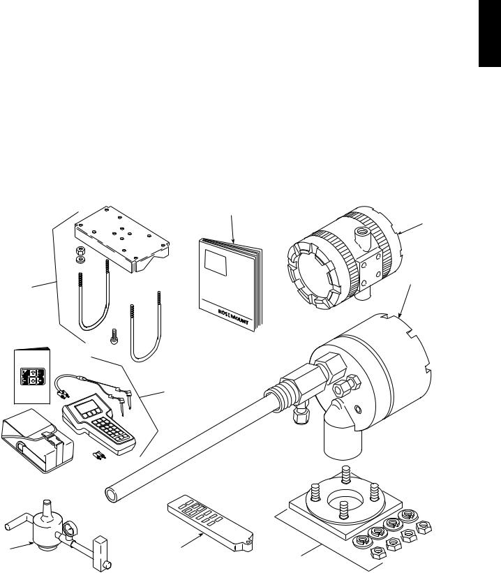
A typical Rosemount Analytical Two-Wire In Situ Oxygen Analyzer should contain the items shown in Figure 1-1. Record the part number, serial number, and order number for each component of your system in the table located on the first
page of this manual. Also, use the product matrix in Table 1-1 to compare your order number against your unit. The first part of the matrix defines the model. The last part defines the various options and features of the analyzer. Ensure the features and options specified by your order number are on or included with the unit.
1
2
3
8
MAN 4275A00
English
October 1994
HART Communicator
o
7
FISHER-ROSEMOUNTTM
|
6 |
5 |
|
|
|
|
4 |
1. |
Instruction Bulletin |
5. |
37240001 |
Infrared Remote Control (IRC) (Optional) |
|||
2. |
Model 5081 Transmitter |
6. |
Reference Air Set (Optional) |
3. |
Oxygen Probe |
7. |
HART® Communicator Package (Optional) |
4. |
Adapter Plate with mounting hardware |
8. |
Pipe Mounting Kit (Optional) |
|
and gasket (Optional) |
|
|
Figure 1-1. Typical System Package
Rosemount Analytical Inc. A Division of Emerson Process Management |
Description and Specifications 1-1 |
Instruction Manual
IB-106-5081, Rev. 1.0
May 2005
Model 5081FG
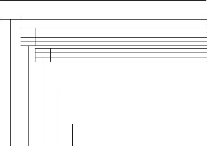
Table 1-1. Product Matrix
5081FG High Temperature Oxygen Flue Gas Analyzer
High Temperature Analyzer - Instruction Book
Code |
Sensing Probe Length |
120 in. (508 mm) probe, 1/4 in. tube fittings
226 in. (660 mm) probe, 1/4 in. tube fittings
334.625 in. (880 mm) probe, 1/4 in. tube fittings
Code Probe Outer Tube Material - Maximum Operating Temperature
1Alumina - 2912°F (1600°C) maximum - 1.25 NPT mounting
2Inconel Alloy - 1832°F (1000°C) maximum - 1.25 NPT mounting
Code |
Mounting Adapter - Stack Side |
0 |
No adapter plate required uses 1.25 NPT |
|
("0" must also be chosen under "Mounting Adapter" below) |
1 |
New flanged installation - Square weld plate with studs (matches "Mounting Adapter" below) |
2 |
Model 450 mounting ("4" must also be chosen under "Mounting Adapter" below) |
3 |
Competitor's Mount ("5" must also be chosen under "Mounting Adapter" below) |
Code |
Mounting Adapter - Probe Side |
0 |
No adapter plate |
1 |
ANSI 2 in. 150 lb flange to 1.25 NPT adapter |
|
(6 in. dia. flange, 4.75 in. BC with 4 x 0.75 in. dia. holes) |
2 |
DIN to 1.25 NPT adapter (184 mm flange, 145 mm BC with 4 x 18 mm dia. holes) |
3 |
JIS to 1.25 NPT adapter (155 mm flange, 130 mm BC with 4 x 13 mm dia. holes) |
4 |
Model 450 to 1.25 NPT adapter |
5 |
Competitor's mounting flange |
Code |
Electronics & Housing - Intrinsically Safe, NEMA 4X, IP65 |
||
1 |
5081 |
Electronics (Hart-compatible) - ATEX EEx ia IIC T5 |
|
2 |
5081 |
Electronics (Hart-compatible) - CSA pending |
|
3 |
5081 |
Electronics (Hart-compatible) - FM Class I, Div. I, Groups B,C,D |
|
|
|
|
|
|
|
|
|
|
|
|
|
|
|
|
|
Code |
Housing Mounting |
|
|
|
||||
|
|
|
|
|
|
|
|
|
|
|
|
0 |
Surface or wall mounting |
|
||||||
|
|
|
|
|
|
|
|
|
|
|
|
1 |
1/2 to 2 in. pipe mounting |
|
||||||
|
|
|
|
|
|
|
|
|
|
|
|
|
|
|
|
|
|
|
|
|
|
|
|
|
|
|
|
|
|
|
|
|
|
|
Code |
Communications |
|
||||
|
|
|
|
|
|
|
|
|
|
|
|
|
|
0 |
No remote control |
|
||||
|
|
|
|
|
|
|
|
|
|
|
|
|
|
1 |
Infrared Remote Control (IRC) |
|||||
|
|
|
|
|
|
|
|
|
|
|
|
|
|
|
|
(LCD display through cover window) |
||||
|
|
|
|
|
|
|
|
|
|
|
|
|
|
|
|
|
|
|
|
|
|
|
|
|
|
|
|
|
|
|
|
|
|
|
|
|
Code |
Calibration Accessories |
|||
|
|
|
|
|
|
|
|
|
|
|
|
|
|
|
|
1 |
No hardware |
|||
|
|
|
|
|
|
|
|
|
|
|
|
|
|
|
|
2 |
Calibration and reference air flowmeters and refer- |
|||
|
|
|
|
|
|
|
|
|
|
|
|
|
|
|
|
|
|
ence air pressure regulator |
||
|
|
|
|
|
|
|
|
|
|
|
|
|
|
|
|
|
|
|
|
|
|
|
|
|
|
|
|
|
|
|
|
|
|
|
|
|
|
|
Code |
Armored Cable Length |
|
|
|
|
|
|
|
|
|
|
|
|
|
|
|
|
|
|
|
00 |
No cable |
|
|
|
|
|
|
|
|
|
|
|
|
|
|
|
|
|
|
|
11 |
20 ft (6 m) |
|
|
|
|
|
|
|
|
|
|
|
|
|
|
|
|
|
|
|
12 |
40 ft (12 m) |
|
|
|
|
|
|
|
|
|
|
|
|
|
|
|
|
|
|
|
13 |
60 ft (18 m) |
|
|
|
|
|
|
|
|
|
|
|
|
|
|
|
|
|
|
|
14 |
80 ft (24 m) |
|
|
|
|
|
|
|
|
|
|
|
|
|
|
|
|
|
|
|
15 |
100 ft (30 m) |
|
|
|
|
|
|
|
|
|
|
|
|
|
|
|
|
|
|
|
16 |
150 ft (45 m) |
|
|
|
|
|
|
|
|
|
|
|
|
|
|
|
|
|
|
|
17 |
200 ft (61 m) |
|
|
|
|
|
|
|
|
|
|
|
|
|
|
|
|
|
|
|
18 |
300 ft (91 m) |
|
|
|
|
|
|
|
|
|
|
|
|
|
|
|
|
|
|
|
19 |
400 ft (122 m) |
|
|
|
|
|
|
|
|
|
|
|
|
|
|
|
|
|
|
|
20 |
500 ft (152 m) |
|
|
|
|
|
|
|
|
|
|
|
|
|
|
|
|
|
|
|
|
|
|
5081FG |
2 |
1 |
0 |
0 |
1 |
1 |
1 |
2 |
11 |
Example |
||||||||||
1-2 Description and Specifications |
Rosemount Analytical Inc. A Division of Emerson Process Management |

Model 5081FG
Instruction Manual
IB-106-5081, Rev. 1.0
May 2005
1
1-2 SYSTEM OVERVIEW
a.Scope
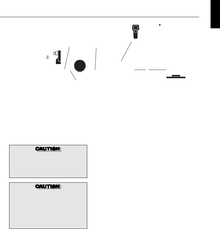
This Instruction Bulletin is designed to supply details needed to install, start up, operate, and maintain the Rosemount Analytical Two-Wire In Situ Oxygen Analyzer. The analyzer consists of an oxygen probe and Model 5081 Transmitter. The signal conditioning electronics of the Model 5081 Transmitter outputs a 4-20 mA signal repre-
senting an O2 value. An infrared remote control (IRC) allows access to setup, calibration, and diagnostics. This same information, plus additional details, can be accessed with the HART Model 275/375 handheld communicator or Asset Management Solutions (AMS) software.
b.System Description
The Rosemount Analytical Two-Wire In Situ Oxygen Analyzer is designed to measure the net concentration of oxygen in an industrial process; i.e., the oxygen remaining after all fuels have been oxidized. The oxygen probe is permanently positioned within an exhaust duct or stack and performs its task without the use of a sampling system. The Model 5081 Transmitter is mounted remotely and conditions the oxygen probe outputs.
The equipment measures oxygen percentage by reading the voltage developed across an electrochemical cell, which consists of a small yttria-stabilized, zirconia disc. Both sides of the disc are coated with porous metal electrodes. The millivolt output voltage of the cell is given by the following Nernst equation:
EMF = KT log10(P1/P2) + C
Where:
1.P2 is the partial pressure of the oxygen in the measured gas on one side of the cell.
2.P1 is the partial pressure of the oxygen in the reference air on the opposite side of the cell.
3.T is the absolute temperature.
4.C is the cell constant.
5.K is an arithmetic constant.
NOTE
For best results, use clean, dry, instrument air (20.95% oxygen) as the reference air.
NOTE
The probe uses a Type B thermocouple to measure the cell temperature.
When the cell is at 550°C to 1600°C (1022°F to 2912°F) and there are unequal oxygen concentrations across the cell, oxygen ions will travel from the high oxygen partial pressure side to the low oxygen partial pressure side of the cell. The resulting logarithmic output voltage is approximately 50 mV per decade.
The output is proportional to the inverse logarithm of the oxygen concentration. Therefore, the output signal increases as the oxygen concentration of the sample gas decreases. This characteristic enables the Rosemount Analytical Two-Wire In Situ Oxygen Analyzer to provide exceptional sensitivity and accuracy at low oxygen concentrations.
Oxygen analyzer equipment measures net oxygen concentration in the presence of all the products of combustion, including water vapor. Therefore, it may be considered an analysis on a "wet" basis. In comparison with older methods, such as the portable apparatus, which provides an analysis on a "dry" gas basis, the "wet" analysis will, in general, indicate a lower percentage of oxygen. The difference will be proportional to the water content of the sampled gas stream.
c.System Configuration
The equipment discussed in this manual consists of two major components: the oxygen probe and the Model 5081 Transmitter.
Oxygen probes are available in three length options, providing in situ penetration appropriate to the size of the stack or duct. The options on length are 20 in. (508 mm), 26 in. (660 mm), or 34.625 in. (880 mm).
Rosemount Analytical Inc. A Division of Emerson Process Management |
Description and Specifications 1-3 |

Instruction Manual
IB-106-5081, Rev. 1.0
May 2005
Model 5081FG
The Model 5081 Transmitter is a two-wire transmitter providing an isolated output, 4- 20 mA, that is proportional to the measured oxygen concentration. A customer-supplied 24 VDC power source is required to simultaneously provide power to the electronics and a 4-20 mA signal loop. The transmitter accepts millivolt signals generated by the probe and produces the outputs to be used by other remotely connected devices. The output is an isolated 4-20 mA linearized current.
d.System Features
1.The cell output voltage and sensitivity increase as the oxygen concentration decreases.
2.High process temperatures eliminate the need for external cell heating and increase cell accuracy.
3.HART communication is standard. To use the HART capability, you must have either:
(a)HART Model 275/375 Communicator
(b)Asset Management Solutions (AMS) software for the PC
4.Easy probe replacement due to the light-weight, compact probe design.
5.Remote location of the Model 5081 Transmitter removes the electronics from high temperature or corrosive environments.
6.Power is supplied to the electronics through the 4-20 mA line for intrinsic safety (IS) purposes.
7.Infrared remote control (IRC) allows interfacing without exposing the electronics.
8.An operator can operate and diagnostically troubleshoot the Two-Wire In Situ Oxygen Analyzer in one of two ways:
(a)Infrared Remote Control. The IRC allows access to fault indication menus on the Model 5081 Transmitter LCD display. Calibration can be performed from the IRC keypad.
(b)Optional HART Interface. The Two-Wire In Situ Oxygen Analyzer’s 4-20 mA output line transmits an analog signal proportional to the oxygen level. The HART output is superimposed on the 4-20 mA output line. This information can be accessed through the following:
1Rosemount Analytical Model 275/375 Handheld Communicator - The handheld communicator requires Device Description (DD) software specific to the Two-Wire In Situ Oxygen Analyzer. The DD software will be supplied with many Model 275/375 units but can also be programmed into existing units at most Fisher-Rosemount Analytical service offices. See Section 4, HART/AMS, for additional HART
information.
2Personal Computer (PC) - The use of a personal computer requires AMS software available from FisherRosemount.
9.Selected Distributed Control Systems - The use of distributed control systems requires input/output (I/O) hardware and AMS Security codes are provided to (by infrared remote control) prevent unintended changes to analyzers adjacent to the one being accessed.
10.A calibration check procedure is provided to determine if the Rosemount Analytical Two-Wire In Situ Oxygen Analyzer is correctly measuring the net oxygen concentration in the industrial process.
1-4 Description and Specifications |
Rosemount Analytical Inc. A Division of Emerson Process Management |
Model 5081FG
Instruction Manual
IB-106-5081, Rev. 1.0
May 2005
1
|
|
|
|
|
|
|
|
|
|
|
|
|
|
|
|
|
|
|
|
|
|
|
|
|
|
|
|
|
|
|
|
|
HART |
|
|
|
|
|
|
|
|
|
|
|
|
|
|
|
|
|
|
|
|
|
|
|
|
|
|
|
|
|
|
|
|
|
|
|
|
|
|
|
|
|
|
|
|
|
|
MODEL 275/375 |
|||||||||||||||||
|
|
|
|
|
|
|
|
|
|
|
|
|
|
|
|
|
|
|
|
|
|
|
|
|
|
|
|
|
|
|
HAND HELD |
|||||||||||||||||
|
|
|
|
|
|
|
|
|
|
|
|
|
|
|
|
|
|
|
|
|
|
|
|
|
|
|
|
|
|
|
|
INTERFACE |
||||||||||||||||
|
TWO-WIRE IN SITU |
O2 |
mV |
|
4-20 mA OUTPUT |
|
|
|
|
|
|
|
|
|
|
|
|
|
|
|
|
|
|
|
|
|
||||||||||||||||||||||
|
SIGNAL |
|
|
|
|
|
|
|
|
|
|
|
|
|
|
|
|
|
|
|
|
|
|
|||||||||||||||||||||||||
|
|
(TWISTED PAIR) |
|
|
|
|
|
|
|
|
|
|
|
|
|
|
|
|
|
|
|
|
|
|||||||||||||||||||||||||
|
OXYGEN ANALYZER |
|
|
|
|
|
|
|
|
|
|
|
|
|
|
|
|
|
|
|
|
|
|
|||||||||||||||||||||||||
|
|
|
|
|
|
|
|
|
|
|
|
|
|
|
|
|
|
|
|
|
|
|
|
|
|
|
|
|
|
|
|
|
|
|
||||||||||||||
|
|
|
|
|
|
|
|
|
|
|
|
|
|
|
|
MODEL 5081 |
|
|
|
|
|
|
|
|
|
|
|
|
|
|
|
|
|
|
|
|
|
|
|
|
|
|
|
|
||||
|
|
|
|
|
|
|
|
|
|
|
|
|
|
|
|
|
|
|
|
|
|
|
|
|
|
|
|
|
|
|
|
|
|
|
|
|
|
|
|
|
|
|
|
|||||
|
|
|
|
|
|
|
|
|
|
|
|
|
|
|
|
|
|
|
|
|
|
|
|
|
|
|
|
|
|
|
|
|
|
|
|
|
|
|
|
|
|
|
|
|||||
|
|
|
|
|
|
|
|
|
|
|
|
|
|
|
|
TRANSMITTER |
|
|
|
|
|
|
|
+ |
|
|
|
|
|
|
|
|
|
|
|
|
|
|
|
|
|
|
|
|||||
CALIBRATION CHECK |
|
|
|
|
|
|
|
|
|
|
|
|
|
|
|
|
|
|
|
|
|
|
|
|
|
|
|
|
|
|
|
|
|
|
|
|
|
|
|
|
|
|
||||||
|
|
|
|
|
|
|
|
|
|
|
|
|
|
|
|
|
|
|
|
|
|
|
|
|
|
|
|
|
|
|
|
|
|
|
|
|
|
|
|
|
||||||||
|
|
|
|
|
|
|
|
|
|
|
|
|
|
|
|
|
|
|
|
|
|
|
|
|
|
|
|
|
|
|
|
|
|
|
|
|
||||||||||||
|
|
|
|
|
|
|
|
|
|
|
|
|
|
|
|
|
|
|
|
|
|
|
|
|
|
|
|
|
|
|
|
|
|
|
|
|
|
|||||||||||
|
GAS LINE |
|
|
|
|
|
|
|
|
|
|
|
|
|
|
|
|
|
|
|
|
|
|
|
|
|
|
|
|
|
|
|
|
|
|
|
||||||||||||
|
|
|
|
|
|
|
|
|
|
|
|
|
|
|
24 VDC |
|
|
|
|
|
|
|
|
|
|
|
|
|
|
|
|
|
||||||||||||||||
|
|
|
|
|
|
|
|
|
|
|
|
|
|
|
|
|
|
|
|
|
|
|
|
|
|
|
|
|
|
|
|
|
|
|
|
|
|
|
|
|
|
|
|
|
||||
|
|
REFERENCE |
TEMPERATURE |
|
|
|
|
|
|
|
POWER |
|
|
|
|
|
|
|
|
|
|
|
|
|
|
|
|
|
||||||||||||||||||||
|
|
|
|
|
|
|
|
|
|
|
|
|
|
|
|
|
|
|
|
|
|
|
|
|||||||||||||||||||||||||
|
|
|
|
|
|
|
|
|
|
|
|
|
|
|
|
|
|
|
|
|
|
|
|
|
|
|
|
|
|
|||||||||||||||||||
|
|
|
|
AIR LINE |
TERMINATION IN |
SUPPLY |
|
|
|
|
|
|
|
|
|
|
|
|
|
|
|
|||||||||||||||||||||||||||
|
|
|
|
|
|
|
|
|
|
|
|
|
|
|
|
|
|
|
|
|
|
|
|
|
||||||||||||||||||||||||
|
|
|
|
mV SIGNAL |
|
|
|
INTRINSIC |
|
|
|
|
|
|
|
|
|
|
|
|
|
|
|
|||||||||||||||||||||||||
|
|
|
|
|
|
|
|
|
|
|
|
|
|
|
CONTROL ROOM |
|
|
|
ASSET MANAGEMENT |
|||||||||||||||||||||||||||||
|
|
|
|
|
|
|
|
|
|
|
|
|
|
|
|
|
|
|
|
|
|
|
|
|
|
|
|
|
|
|
SAFETY |
|||||||||||||||||
|
|
|
|
|
|
|
|
|
|
|
|
|
|
|
|
|
|
|
|
|
|
|
|
|
|
|
|
|
|
|
BARRIER |
|
|
|
SOLUTIONS |
|||||||||||||
|
|
|
|
|
|
|
|
|
|
|
|
|
|
|
|
|
|
|
|
|
|
|
|
|
|
|
|
|
|
|
(OPTIONAL) |
37240002 |
||||||||||||||||
|
|
|
|
|
|
|
|
|
|
|
|
|
|
|
|
|
|
|
|
|
|
|
|
|
|
|
|
|
|
|
|
|
|
|||||||||||||||
|
Figure 1-2. Two-Wire In Situ Oxygen Analyzer HART Connections and AMS Application |
|||||||||||||||||||||||||||||||||||||||||||||||
|
e. Handling the Analyzer |
|
|
|
|
|
|
|
|
|
f. |
System Considerations |
||||||||||||||||||||||||||||||||||||
The probe was specially packaged to prevent breakage due to handling. Do not remove the padding material from the probe until immediately before installation.
It is important that printed circuit boards and integrated circuits are handled only when adequate antistatic precautions have been taken to prevent possible equipment damage.
The oxygen probe is designed for industrial applications. Treat with care to avoid physical damage. The probe contains components made from ceramic, which are susceptible to shock when mishandled. THE WARRANTY DOES NOT COVER DAMAGE FROM MISHANDLING.
Prior to installing your Rosemount Analytical Two-Wire In Situ Oxygen Analyzer, make sure you have all the components necessary to make the system installation. Ensure all the components are properly integrated to make the system functional.
After verifying that you have all the components, select mounting locations and determine how each component will be placed in terms of available line voltage, ambient temperatures, environmental considerations, convenience, and serviceability. Figure 1-2 shows a typical system wiring. A typical system installation is illustrated in Figure 1-3.
Rosemount Analytical Inc. A Division of Emerson Process Management |
Description and Specifications 1-5 |
Loading...