


 Loading...


 Precision Cooling


 For Business-Critical Continuity™


 Liebert® Challenger™ 3000 with Liebert iCOM®


 Installation Manual - 3 & 5 Tons, 50 & 60Hz

TABLE OF CONTENTS
IMPORTANT SAFETY INSTRUCTIONS . . . . . . . . . . . . . . . . . . . . . . . . . . . . . . . . . . . . . . . . . . . . . . . .1 SAVE THESE INSTRUCTIONS . . . . . . . . . . . . . . . . . . . . . . . . . . . . . . . . . . . . . . . . . . . . . . . . . . . . .1 1.0 INTRODUCTION . . . . . . . . . . . . . . . . . . . . . . . . . . . . . . . . . . . . . . . . . . . . . . . . . . . . . . . . . .4
1.1 System Descriptions. . . . . . . . . . . . . . . . . . . . . . . . . . . . . . . . . . . . . . . . . . . . . . . . . . . . . . . . . . 4
1.1.1 Self-Contained Systems . . . . . . . . . . . . . . . . . . . . . . . . . . . . . . . . . . . . . . . . . . . . . . . . . . . . . . . . 4 1.1.2 Chilled Water Models. . . . . . . . . . . . . . . . . . . . . . . . . . . . . . . . . . . . . . . . . . . . . . . . . . . . . . . . . . 4 1.1.3 Split Systems . . . . . . . . . . . . . . . . . . . . . . . . . . . . . . . . . . . . . . . . . . . . . . . . . . . . . . . . . . . . . . . . 5
2.0 INSTALLATION (APPLICABLE TO ALL MODELS). . . . . . . . . . . . . . . . . . . . . . . . . . . . . . . . . . .6
2.1 Room Preparation. . . . . . . . . . . . . . . . . . . . . . . . . . . . . . . . . . . . . . . . . . . . . . . . . . . . . . . . . . . . 6 2.2 Equipment Inspection . . . . . . . . . . . . . . . . . . . . . . . . . . . . . . . . . . . . . . . . . . . . . . . . . . . . . . . . 6 2.3 Location Considerations. . . . . . . . . . . . . . . . . . . . . . . . . . . . . . . . . . . . . . . . . . . . . . . . . . . . . . . 6 2.4 Equipment Handling . . . . . . . . . . . . . . . . . . . . . . . . . . . . . . . . . . . . . . . . . . . . . . . . . . . . . . . . . 6
2.4.1 Handling With Skid . . . . . . . . . . . . . . . . . . . . . . . . . . . . . . . . . . . . . . . . . . . . . . . . . . . . . . . . . . . 7 2.4.2 Removal of Skid . . . . . . . . . . . . . . . . . . . . . . . . . . . . . . . . . . . . . . . . . . . . . . . . . . . . . . . . . . . . . . 7
2.5 Piping Considerations . . . . . . . . . . . . . . . . . . . . . . . . . . . . . . . . . . . . . . . . . . . . . . . . . . . . . . . 10
2.5.1 Drain Line. . . . . . . . . . . . . . . . . . . . . . . . . . . . . . . . . . . . . . . . . . . . . . . . . . . . . . . . . . . . . . . . . . 10 2.5.2 Humidifier Supply Water—Optional Infrared . . . . . . . . . . . . . . . . . . . . . . . . . . . . . . . . . . . . . 19
2.6 Facility Fluid and Piping Maintenance. . . . . . . . . . . . . . . . . . . . . . . . . . . . . . . . . . . . . . . . . . 19 2.7 Electrical Connections . . . . . . . . . . . . . . . . . . . . . . . . . . . . . . . . . . . . . . . . . . . . . . . . . . . . . . . 19
2.7.1 Electrical Field Connections for Liebert Challenger 3000 Models . . . . . . . . . . . . . . . . . . . . . 20
2.8 Balancing the Air Distribution . . . . . . . . . . . . . . . . . . . . . . . . . . . . . . . . . . . . . . . . . . . . . . . . 22
2.8.1 Under-Floor Discharge Systems . . . . . . . . . . . . . . . . . . . . . . . . . . . . . . . . . . . . . . . . . . . . . . . . 22 2.8.2 Ducted Applications . . . . . . . . . . . . . . . . . . . . . . . . . . . . . . . . . . . . . . . . . . . . . . . . . . . . . . . . . . 22 2.8.3 Plenum Installation . . . . . . . . . . . . . . . . . . . . . . . . . . . . . . . . . . . . . . . . . . . . . . . . . . . . . . . . . . 22
2.9 Checklist for Completed Installation . . . . . . . . . . . . . . . . . . . . . . . . . . . . . . . . . . . . . . . . . . . 23
3.0 AIR-COOLED MODELS—SELF-CONTAINED COMPRESSOR . . . . . . . . . . . . . . . . . . . . . . . . .24
3.1 Condenser Location . . . . . . . . . . . . . . . . . . . . . . . . . . . . . . . . . . . . . . . . . . . . . . . . . . . . . . . . . 24 3.2 Electrical Connections . . . . . . . . . . . . . . . . . . . . . . . . . . . . . . . . . . . . . . . . . . . . . . . . . . . . . . . 24
3.2.1 Line Voltage . . . . . . . . . . . . . . . . . . . . . . . . . . . . . . . . . . . . . . . . . . . . . . . . . . . . . . . . . . . . . . . . 24 3.2.2 Low Voltage . . . . . . . . . . . . . . . . . . . . . . . . . . . . . . . . . . . . . . . . . . . . . . . . . . . . . . . . . . . . . . . . 24 3.2.3 Liebert Lee-Temp™/Flood Back Head Pressure Control Condensers . . . . . . . . . . . . . . . . . . . 24
3.3 Refrigerant Piping . . . . . . . . . . . . . . . . . . . . . . . . . . . . . . . . . . . . . . . . . . . . . . . . . . . . . . . . . . 26 3.4 Fan Speed Control Systems . . . . . . . . . . . . . . . . . . . . . . . . . . . . . . . . . . . . . . . . . . . . . . . . . . . 28
3.5Air-Cooled Condenser with Liebert Lee-Temp™ “Flooded Condenser” Head Pressure
Control System . . . . . . . . . . . . . . . . . . . . . . . . . . . . . . . . . . . . . . . . . . . . . . . . . . . . . . . . . . . . . 32
4.0 WATER-COOLED MODELS—SELF-CONTAINED COMPRESSOR . . . . . . . . . . . . . . . . . . . . . .36
4.1 Piping Considerations . . . . . . . . . . . . . . . . . . . . . . . . . . . . . . . . . . . . . . . . . . . . . . . . . . . . . . . 36
4.2 Condenser . . . . . . . . . . . . . . . . . . . . . . . . . . . . . . . . . . . . . . . . . . . . . . . . . . . . . . . . . . . . . . . . . 36
i
4.3 Water Regulating Valve. . . . . . . . . . . . . . . . . . . . . . . . . . . . . . . . . . . . . . . . . . . . . . . . . . . . . . 39
4.3.1Standard Valve - 150psig (1034kPa) System for 3 & 5-Ton Units (Johnson Controls
Valve) High Pressure Valve - 350psig (2413kPa) System for 5-Ton Units (Johnson
Controls Valve) . . . . . . . . . . . . . . . . . . . . . . . . . . . . . . . . . . . . . . . . . . . . . . . . . . . . . . . . . . . . . . 39 4.3.2 High Pressure Valve - 350 psig (2413 kPa) System for 3-Ton Units (Metrex Valve) . . . . . . . 40
4.4 Motorized Ball Valve—Digital Scroll Compressors . . . . . . . . . . . . . . . . . . . . . . . . . . . . . . . . 40
4.4.1 Control. . . . . . . . . . . . . . . . . . . . . . . . . . . . . . . . . . . . . . . . . . . . . . . . . . . . . . . . . . . . . . . . . . . . . 40 4.4.2 Adjustment . . . . . . . . . . . . . . . . . . . . . . . . . . . . . . . . . . . . . . . . . . . . . . . . . . . . . . . . . . . . . . . . . 41 4.4.3 Startup . . . . . . . . . . . . . . . . . . . . . . . . . . . . . . . . . . . . . . . . . . . . . . . . . . . . . . . . . . . . . . . . . . . . 41 4.4.4 Location. . . . . . . . . . . . . . . . . . . . . . . . . . . . . . . . . . . . . . . . . . . . . . . . . . . . . . . . . . . . . . . . . . . . 41 4.4.5 Manual Control. . . . . . . . . . . . . . . . . . . . . . . . . . . . . . . . . . . . . . . . . . . . . . . . . . . . . . . . . . . . . . 41
5.0 GLYCOL/GLYCOOL-COOLED MODELS—SELF-CONTAINED COMPRESSOR . . . . . . . . . . . .42
5.1 Drycooler Location . . . . . . . . . . . . . . . . . . . . . . . . . . . . . . . . . . . . . . . . . . . . . . . . . . . . . . . . . . 42 5.2 Drycooler Installation . . . . . . . . . . . . . . . . . . . . . . . . . . . . . . . . . . . . . . . . . . . . . . . . . . . . . . . 42 5.3 Electrical Connections . . . . . . . . . . . . . . . . . . . . . . . . . . . . . . . . . . . . . . . . . . . . . . . . . . . . . . . 42
5.3.1 Line Voltage . . . . . . . . . . . . . . . . . . . . . . . . . . . . . . . . . . . . . . . . . . . . . . . . . . . . . . . . . . . . . . . . 42 5.3.2 Low Voltage . . . . . . . . . . . . . . . . . . . . . . . . . . . . . . . . . . . . . . . . . . . . . . . . . . . . . . . . . . . . . . . . 42 5.3.3 Pump and Drycooler . . . . . . . . . . . . . . . . . . . . . . . . . . . . . . . . . . . . . . . . . . . . . . . . . . . . . . . . . . 42
5.4 Glycol Piping. . . . . . . . . . . . . . . . . . . . . . . . . . . . . . . . . . . . . . . . . . . . . . . . . . . . . . . . . . . . . . . 43
5.4.1 Expansion Tanks, Fluid Relief Valves and Other Devices. . . . . . . . . . . . . . . . . . . . . . . . . . . . 45
5.5 Filling Instructions. . . . . . . . . . . . . . . . . . . . . . . . . . . . . . . . . . . . . . . . . . . . . . . . . . . . . . . . . . 45
5.5.1 Preparing the System for Filling . . . . . . . . . . . . . . . . . . . . . . . . . . . . . . . . . . . . . . . . . . . . . . . . 45 5.5.2 Glycol Solutions . . . . . . . . . . . . . . . . . . . . . . . . . . . . . . . . . . . . . . . . . . . . . . . . . . . . . . . . . . . . . 46 5.5.3 Filling the System . . . . . . . . . . . . . . . . . . . . . . . . . . . . . . . . . . . . . . . . . . . . . . . . . . . . . . . . . . . 47 5.5.4 Motor Ball Valve—Digital Scroll Compressors. . . . . . . . . . . . . . . . . . . . . . . . . . . . . . . . . . . . . 54
5.6 Condenser . . . . . . . . . . . . . . . . . . . . . . . . . . . . . . . . . . . . . . . . . . . . . . . . . . . . . . . . . . . . . . . . . 54 5.7 Glycol Regulating Valve. . . . . . . . . . . . . . . . . . . . . . . . . . . . . . . . . . . . . . . . . . . . . . . . . . . . . . 54
5.7.1Standard Valve - 150psig (1034kPa) System for 3 & 5-Ton Units (Johnson Controls
Valve) High Pressure Valve - 350psig (2413kPa) System for 5-Ton Units (Johnson
Controls Valve) . . . . . . . . . . . . . . . . . . . . . . . . . . . . . . . . . . . . . . . . . . . . . . . . . . . . . . . . . . . . . . 54 5.7.2 High Pressure Valve - 350 psig (2413 kPa) System for 3-Ton Units (Metrex Valve) . . . . . . . 54 5.7.3 Testing Valve Function . . . . . . . . . . . . . . . . . . . . . . . . . . . . . . . . . . . . . . . . . . . . . . . . . . . . . . . 54
6.0 CHILLED WATER MODELS. . . . . . . . . . . . . . . . . . . . . . . . . . . . . . . . . . . . . . . . . . . . . . . . .55
6.1 Piping Considerations . . . . . . . . . . . . . . . . . . . . . . . . . . . . . . . . . . . . . . . . . . . . . . . . . . . . . . . 55
7.0 SPLIT SYSTEM MODELS . . . . . . . . . . . . . . . . . . . . . . . . . . . . . . . . . . . . . . . . . . . . . . . . . .57
7.1 Location Considerations. . . . . . . . . . . . . . . . . . . . . . . . . . . . . . . . . . . . . . . . . . . . . . . . . . . . . . 57
7.1.1 Air-Cooled Condensing Units. . . . . . . . . . . . . . . . . . . . . . . . . . . . . . . . . . . . . . . . . . . . . . . . . . . 57 7.1.2 Water/Glycol-Cooled Condensing Units . . . . . . . . . . . . . . . . . . . . . . . . . . . . . . . . . . . . . . . . . . 57
7.2 Electrical Connections . . . . . . . . . . . . . . . . . . . . . . . . . . . . . . . . . . . . . . . . . . . . . . . . . . . . . . . 57
7.2.1 Line Voltage . . . . . . . . . . . . . . . . . . . . . . . . . . . . . . . . . . . . . . . . . . . . . . . . . . . . . . . . . . . . . . . . 58 7.2.2 Low Voltage . . . . . . . . . . . . . . . . . . . . . . . . . . . . . . . . . . . . . . . . . . . . . . . . . . . . . . . . . . . . . . . . 58
7.3 Piping Considerations . . . . . . . . . . . . . . . . . . . . . . . . . . . . . . . . . . . . . . . . . . . . . . . . . . . . . . . 58
7.3.1 Refrigerant Loop. . . . . . . . . . . . . . . . . . . . . . . . . . . . . . . . . . . . . . . . . . . . . . . . . . . . . . . . . . . . . 58 7.3.2 Quick Connect Fittings . . . . . . . . . . . . . . . . . . . . . . . . . . . . . . . . . . . . . . . . . . . . . . . . . . . . . . . 61

7.4 Outdoor Air-Cooled Condensing Units . . . . . . . . . . . . . . . . . . . . . . . . . . . . . . . . . . . . . . . . . . 62
7.5 Centrifugal Air-Cooled Condensing Units . . . . . . . . . . . . . . . . . . . . . . . . . . . . . . . . . . . . . . . 67
7.5.1 Installing the Indoor Condensing Unit . . . . . . . . . . . . . . . . . . . . . . . . . . . . . . . . . . . . . . . . . . . 67
7.5.2 Ducting . . . . . . . . . . . . . . . . . . . . . . . . . . . . . . . . . . . . . . . . . . . . . . . . . . . . . . . . . . . . . . . . . . . . 68
7.6 Water and Glycol-Cooled Condensing Units. . . . . . . . . . . . . . . . . . . . . . . . . . . . . . . . . . . . . . 74
7.6.1 Piping Considerations . . . . . . . . . . . . . . . . . . . . . . . . . . . . . . . . . . . . . . . . . . . . . . . . . . . . . . . . 74
7.6.2 Condenser Water Requirements . . . . . . . . . . . . . . . . . . . . . . . . . . . . . . . . . . . . . . . . . . . . . . . . 74
7.6.3 Regulating Valve . . . . . . . . . . . . . . . . . . . . . . . . . . . . . . . . . . . . . . . . . . . . . . . . . . . . . . . . . . . . 74
7.6.4 Glycol Systems . . . . . . . . . . . . . . . . . . . . . . . . . . . . . . . . . . . . . . . . . . . . . . . . . . . . . . . . . . . . . . 75
8.0 R407C REFRIGERANT . . . . . . . . . . . . . . . . . . . . . . . . . . . . . . . . . . . . . . . . . . . . . . . . . . .79
8.1 Calculating Subcooling. . . . . . . . . . . . . . . . . . . . . . . . . . . . . . . . . . . . . . . . . . . . . . . . . . . . . . . 80
FIGURES
Figure 1 Removing the Liebert Challenger 3000 from skid . . . . . . . . . . . . . . . . . . . . . . . . . . . . . . . . . . . . . . 7 Figure 2 Upflow (BU) cabinet dimensions . . . . . . . . . . . . . . . . . . . . . . . . . . . . . . . . . . . . . . . . . . . . . . . . . . . . 8 Figure 3 Downflow (BF) cabinet dimensions . . . . . . . . . . . . . . . . . . . . . . . . . . . . . . . . . . . . . . . . . . . . . . . . . . 9 Figure 4 Piping connections for air-cooled units - Downflow models . . . . . . . . . . . . . . . . . . . . . . . . . . . . . . 11 Figure 5 Piping connections for air-cooled units - Upflow models . . . . . . . . . . . . . . . . . . . . . . . . . . . . . . . . 12 Figure 6 Piping connections for split system fan coil units - Downflow models . . . . . . . . . . . . . . . . . . . . . 13 Figure 7 Piping connections for split system fan coil units - Upflow models . . . . . . . . . . . . . . . . . . . . . . . 14 Figure 8 Piping connections for water/glycol and GLYCOOL units - Downflow models . . . . . . . . . . . . . . 15 Figure 9 Piping connections for water/glycol and GLYCOOL units - Upflow models . . . . . . . . . . . . . . . . . 16 Figure 10 Piping connections for chilled water self-contained units - Downflow models . . . . . . . . . . . . . . . 17 Figure 11 Piping connections for chilled water self-contained units - Upflow models . . . . . . . . . . . . . . . . . 18
Figure 12 Electrical connections . . . . . . . . . . . . . . . . . . . . . . . . . . . . . . . . . . . . . . . . . . . . . . . . . . . . . . . . . . . . 20 Figure 13 Electrical field connections for Liebert iCOM® . . . . . . . . . . . . . . . . . . . . . . . . . . . . . . . . . . . . . . . . 21
Figure 14 Air-cooled condensers . . . . . . . . . . . . . . . . . . . . . . . . . . . . . . . . . . . . . . . . . . . . . . . . . . . . . . . . . . . . 25 Figure 15 General arrangement—Air-cooled models with fan speed control. . . . . . . . . . . . . . . . . . . . . . . . . 30 Figure 16 General arrangement—Air-cooled models with digital scroll and fan speed control . . . . . . . . . . 31 Figure 17 General arrangement—Air-cooled models with Liebert Lee-Temp™ . . . . . . . . . . . . . . . . . . . . . . 34 Figure 18 General arrangement—Air-cooled models with digital scroll and Liebert Lee-Temp™ . . . . . . . . 35 Figure 19 General arrangement—Water-cooled models with scroll compressor . . . . . . . . . . . . . . . . . . . . . . 37 Figure 20 General arrangement diagram—Water-cooled models with digital scroll . . . . . . . . . . . . . . . . . . 38 Figure 21 Johnson Controls valve adjustment. . . . . . . . . . . . . . . . . . . . . . . . . . . . . . . . . . . . . . . . . . . . . . . . . 39 Figure 22 Metrex Valve adjustment . . . . . . . . . . . . . . . . . . . . . . . . . . . . . . . . . . . . . . . . . . . . . . . . . . . . . . . . . 40 Figure 23 Drycoolers and pump packages . . . . . . . . . . . . . . . . . . . . . . . . . . . . . . . . . . . . . . . . . . . . . . . . . . . . 48 Figure 24 Pump packages—expansion tank . . . . . . . . . . . . . . . . . . . . . . . . . . . . . . . . . . . . . . . . . . . . . . . . . . 49 Figure 25 General arrangement—Glycol-cooled models with scroll compressor . . . . . . . . . . . . . . . . . . . . . . 50 Figure 26 General arrangement—Glycol-cooled models with digital scroll . . . . . . . . . . . . . . . . . . . . . . . . . . 51 Figure 27 General arrangement—GLYCOOL models with scroll compressor. . . . . . . . . . . . . . . . . . . . . . . . 52 Figure 28 General arrangement—GLYCOOL models with digital scroll compressor . . . . . . . . . . . . . . . . . . 53 Figure 29 Chilled water general arrangement - Upflow (BU). . . . . . . . . . . . . . . . . . . . . . . . . . . . . . . . . . . . . 55 Figure 30 Chilled water general arrangement - Downflow (BF) models . . . . . . . . . . . . . . . . . . . . . . . . . . . . 56 Figure 31 Refrigerant piping diagram . . . . . . . . . . . . . . . . . . . . . . . . . . . . . . . . . . . . . . . . . . . . . . . . . . . . . . . 60 Figure 32 Outdoor air-cooled condensing unit—horizontal air discharge models . . . . . . . . . . . . . . . . . . . . . 62 Figure 33 Outdoor air-cooled condensing unit—top air discharge models . . . . . . . . . . . . . . . . . . . . . . . . . . . 64 Figure 34 Electrical field connections, prop fan condensing module . . . . . . . . . . . . . . . . . . . . . . . . . . . . . . . 66 Figure 35 Detail of ceiling hanging bracket . . . . . . . . . . . . . . . . . . . . . . . . . . . . . . . . . . . . . . . . . . . . . . . . . . . 68
iii
Figure 36 3-ton centrifugal air-cooled condensing unit dimensional data & piping connections . . . . . . . . . 69 Figure 37 3-ton centrifugal air-cooled condensing unit (con’t.) . . . . . . . . . . . . . . . . . . . . . . . . . . . . . . . . . . . . 70 Figure 38 5-ton centrifugal air-cooled condensing unit dimensional data . . . . . . . . . . . . . . . . . . . . . . . . . . . 71 Figure 39 5-ton centrifugal air-cooled condensing unit dimensional data (con’t.) . . . . . . . . . . . . . . . . . . . . . 72 Figure 40 Split systems general arrangement . . . . . . . . . . . . . . . . . . . . . . . . . . . . . . . . . . . . . . . . . . . . . . . . . 73 Figure 41 3-ton water/glycol-cooled condensing unit . . . . . . . . . . . . . . . . . . . . . . . . . . . . . . . . . . . . . . . . . . . . 75 Figure 42 3-ton water/glycol-cooled condensing unit (con’t.) . . . . . . . . . . . . . . . . . . . . . . . . . . . . . . . . . . . . . . 76 Figure 43 5-ton water/glycol-cooled condensing unit dimensional data . . . . . . . . . . . . . . . . . . . . . . . . . . . . . 77 Figure 44 5-ton water/glycol-cooled condensing unit (con’t.) . . . . . . . . . . . . . . . . . . . . . . . . . . . . . . . . . . . . . . 78
TABLES
Table 1 Unit net weight . . . . . . . . . . . . . . . . . . . . . . . . . . . . . . . . . . . . . . . . . . . . . . . . . . . . . . . . . . . . . . . . . . 7 Table 2 Piping connection size. . . . . . . . . . . . . . . . . . . . . . . . . . . . . . . . . . . . . . . . . . . . . . . . . . . . . . . . . . . . 10
Table 3 Recommended free area ft2 (m2) for grilles or perforated panels at output velocities of 550
and 600 fpm (2.8 and 3.1 m/s) . . . . . . . . . . . . . . . . . . . . . . . . . . . . . . . . . . . . . . . . . . . . . . . . . . . . . 22 Table 4 Air-cooled condenser statistics . . . . . . . . . . . . . . . . . . . . . . . . . . . . . . . . . . . . . . . . . . . . . . . . . . . . . 25 Table 5 Recommended line sizes — OD copper, inches *. . . . . . . . . . . . . . . . . . . . . . . . . . . . . . . . . . . . . . . 27 Table 6 Equivalent lengths (feet) for various pipe fittings . . . . . . . . . . . . . . . . . . . . . . . . . . . . . . . . . . . . . 27 Table 7 Indoor unit refrigerant charge . . . . . . . . . . . . . . . . . . . . . . . . . . . . . . . . . . . . . . . . . . . . . . . . . . . . . 27 Table 8 Line charges - refrigerant per 100 ft. (30 m) of Type “L” copper tube . . . . . . . . . . . . . . . . . . . . . . 27 Table 9 Condenser refrigerant (per serial tag) . . . . . . . . . . . . . . . . . . . . . . . . . . . . . . . . . . . . . . . . . . . . . . . 27 Table 10 Fan speed suction pressure transducer settings . . . . . . . . . . . . . . . . . . . . . . . . . . . . . . . . . . . . . . . 29 Table 11 Liebert Lee-Temp suction pressure transducer settings . . . . . . . . . . . . . . . . . . . . . . . . . . . . . . . . 33 Table 12 Refrigerant control settings psi (kPa) . . . . . . . . . . . . . . . . . . . . . . . . . . . . . . . . . . . . . . . . . . . . . . . 40 Table 13 Room dew point temperatures . . . . . . . . . . . . . . . . . . . . . . . . . . . . . . . . . . . . . . . . . . . . . . . . . . . . . 44 Table 14 Indoor unit glycol volume approximate gallons (liters) max. . . . . . . . . . . . . . . . . . . . . . . . . . . . . 45 Table 15 Volume in standard Type “L” copper piping . . . . . . . . . . . . . . . . . . . . . . . . . . . . . . . . . . . . . . . . . . 45 Table 16 Ethylene glycol concentrations. . . . . . . . . . . . . . . . . . . . . . . . . . . . . . . . . . . . . . . . . . . . . . . . . . . . . 46 Table 17 Mounting hole dimensional data . . . . . . . . . . . . . . . . . . . . . . . . . . . . . . . . . . . . . . . . . . . . . . . . . . . 49 Table 18 Drycooler data . . . . . . . . . . . . . . . . . . . . . . . . . . . . . . . . . . . . . . . . . . . . . . . . . . . . . . . . . . . . . . . . . . 49 Table 19 Glycol pump data* . . . . . . . . . . . . . . . . . . . . . . . . . . . . . . . . . . . . . . . . . . . . . . . . . . . . . . . . . . . . . . 49 Table 20 Refrigerant control settings psi (kPa) . . . . . . . . . . . . . . . . . . . . . . . . . . . . . . . . . . . . . . . . . . . . . . . 54 Table 21 Unit refrigerant charge . . . . . . . . . . . . . . . . . . . . . . . . . . . . . . . . . . . . . . . . . . . . . . . . . . . . . . . . . . 59 Table 22 Recommended refrigerant lines (R407C) sizes OD copper . . . . . . . . . . . . . . . . . . . . . . . . . . . . . . . 60 Table 23 Line coupling sizes . . . . . . . . . . . . . . . . . . . . . . . . . . . . . . . . . . . . . . . . . . . . . . . . . . . . . . . . . . . . . . 60 Table 24 Equivalent lengths (feet) for various pipe fittings . . . . . . . . . . . . . . . . . . . . . . . . . . . . . . . . . . . . . 60 Table 25 Line charges - refrigerant per 100 ft. (30 m) of Type “L” copper tube . . . . . . . . . . . . . . . . . . . . . . 60 Table 26 Horizontal air discharge cabinet and floor planning dimensional data. . . . . . . . . . . . . . . . . . . . . 63 Table 27 Horizontal air discharge piping and electrical connection data . . . . . . . . . . . . . . . . . . . . . . . . . . . 63
Table 28 Cabinet and floor planning dimensional data - prop fan condensing modules, top air
discharge . . . . . . . . . . . . . . . . . . . . . . . . . . . . . . . . . . . . . . . . . . . . . . . . . . . . . . . . . . . . . . . . . . . . . . 65 Table 29 Piping and electrical connections - top air discharge . . . . . . . . . . . . . . . . . . . . . . . . . . . . . . . . . . . 65 Table 30 Indoor centrifugal condensing unit . . . . . . . . . . . . . . . . . . . . . . . . . . . . . . . . . . . . . . . . . . . . . . . . . 67 Table 31 Airflow CFM (CMH) . . . . . . . . . . . . . . . . . . . . . . . . . . . . . . . . . . . . . . . . . . . . . . . . . . . . . . . . . . . . . 68 Table 32 Water and glycol-cooled condensing unit data . . . . . . . . . . . . . . . . . . . . . . . . . . . . . . . . . . . . . . . . 74
Table 33 R407C pressure/temperature chart for operation and superheat (discharge/hot gas and
suction gas) . . . . . . . . . . . . . . . . . . . . . . . . . . . . . . . . . . . . . . . . . . . . . . . . . . . . . . . . . . . . . . . . . . . . 79 Table 34 R407C pressure/temperature chart for subcooling only (liquid measurements). . . . . . . . . . . . . . 80
Important Safety Instructions
IMPORTANT SAFETY INSTRUCTIONS
SAVE THESE INSTRUCTIONS
This manual contains important safety instructions that should be followed during the installation and maintenance of the Liebert Challenger 3000. Read this manual thoroughly before attempting to install or operate this unit.
Only qualified personnel should move, install or service this equipment.
Adhere to all warnings, cautions and installation, operating and safety instructions on the unit and in this manual. Follow all operating and user instructions.
! WARNING
Arc flash and electric shock hazard. Disconnect all local and remote electric power supplies and wear protective equipment per NFPA 70E before working within the electrical enclosure. Failure to comply can cause injury or death.
Customer must provide earth ground to unit per NEC, CEC and local codes as applicable.
Before proceeding with installation, read all instructions, verify that all the parts are included and check the nameplate to be sure the voltage matches available utility power.
The Liebert iCOM® microprocessor does not isolate power from the unit, even in the “Unit Off” mode. Some internal components require and receive power even during the “Unit Off” mode of Liebert iCOM control.
The factory-supplied optional disconnect switch is inside the unit. The line side of this switch contains live high-voltage.
The only way to ensure that there is NO voltage inside the unit is to install and open a remote disconnect switch and check the internal power with a voltmeter. Refer to unit electrical schematic.
Follow all local codes.
! WARNING
Risk of explosive discharge from high-pressure refrigerant. Can cause injury or death. This unit contains fluids and/or gases under high pressure.
Relieve pressure before working with piping.
! WARNING
Risk of refrigerant system rupture or explosion from overpressurization. Can cause equipment damage, injury or death.
Local building or plumbing codes may require that a fusible plug or other type of pressure relief device be installed in the system.
For systems requiring EU CE compliance (50Hz), the system installer must provide and install a discharge pressure relief valve rated for a maximum of 500psig (34bar) in the high side refrigerant circuit. Do not install a shutoff valve between the compressor and the field-installed relief valve. The pressure relief valve must be CE certified to the EU Pressure Equipment Directive by an EU “Notified Body.”
NOTE
The Liebert indoor cooling unit has a factory-installed high-pressure safety switch in the high side refrigerant circuit. A pressure relief valve is provided with Liebert Lee-Temp™ condensers. Consult local building codes to determine whether the Liebert Fan Speed Control and VFD condensers will require field-provided pressure relief devices. A fusible plug kit for Liebert FSC and VFD condensers is available for field installation.
1 |
Liebert® Challenger 3000™ |
Important Safety Instructions
! WARNING
Risk of improper handling of top heavy unit. Can cause unit to fall over, resulting in equipment damage, serious injury or death.
Read all instructions before attempting to move, lift, remove packaging from or preparing unit for installation.
! WARNING
Risk of high-speed moving parts. Can cause injury or death.
Disconnect all local and remote electric power supplies before working in the unit.
Do not operate upflow units without installing a plenum, ductwork or guard over the blower opening(s) on the top surface of the unit cabinet for protection from rotating blower wheel(s).
! CAUTION
Risk of contact with hot surfaces. Can cause injury.
The compressor, refrigerant discharge lines, humidifiers and reheats are extremely hot during unit operation. Allow sufficient time for them to cool before working within the unit cabinet. Use extreme caution and wear protective gloves and arm protection when working on or near hot compressors, discharge lines, humidifiers and reheats.
! CAUTION
Risk of sharp edges, splinters and exposed fasteners. Can cause injury.
Only properly trained and qualified personnel wearing appropriate safety headgear, gloves, shoes and glasses should attempt to move the unit, lift it, remove packaging from or prepare the unit for installation.
NOTICE
Risk of leaking water/glycol. Can cause equipment and building damage.
This unit requires a water/glycol. drain connection. It may also require an external water/glycol supply to operate.
Improper installation, application and service practice can result in water/glycol leakage from the unit. Water/glycol leakage can result in severe property damage and loss of critical data center equipment.
Do not locate unit directly above any equipment that could sustain water damage.
Emerson recommends installing monitored leak detection equipment for unit and water/glycol supply lines.
NOTICE
Risk of a leaking coil due to freezing and/or corrosion. Can cause equipment and building damage.
Cooling coils and piping systems that are connected to open cooling towers or other open water/glycol systems are at high risk of freezing and premature corrosion. Fluids in these systems must contain the proper antifreeze and inhibitors to prevent freezing and premature coil corrosion. The water or water/glycol solution must be analyzed by a competent water treatment specialist before startup to establish the inhibitor requirement. The water or water/glycol solution must be analyzed every six months to determine the pattern of inhibitor depletion. The complexity of water-caused problems and their correction makes it important to obtain the advice of a water treatment specialist and follow a regularly scheduled maintenance program.
Liebert® Challenger 3000™ |
2 |

Important Safety Instructions
NOTICE
Risk of damage from forklift. Can cause unit damage.
Keep tines of the forklift level and at a height suitable to fit below the skid and/or unit to prevent exterior and/or underside damage.
NOTICE
Risk of improper storage. Can cause unit damage.
Keep the Liebert Challenger 3000 upright, indoors and protected from dampness, freezing temperatures and contact damage.
3 |
Liebert® Challenger 3000™ |

Introduction
1.0INTRODUCTION
1.1System Descriptions
Liebert Challenger 3000 Precision Cooling systems are available in three main system configurations:
•self-contained system with a scroll compressor in the room unit
•self-contained chilled water system
•split system with an evaporator section and a remote condensing unit
All three types are available in upflow or downflow configurations. The standard upflow configuration is front return. All models require three-phase power. Units are available in 208, 230, 460, or 575V, 60Hz; and 200, 230 or 380/415V, 50Hz.
The following features are included as standard in all room units regardless of the type of system: Liebert iCOM® control, A-frame coil (V-frame on upflows), infrared humidifier, finned tubular stainless steel electric reheat, 2" filter, individual high voltage fused protection and fan assembly.
1.1.1Self-Contained Systems Air-Cooled Models
Complete refrigeration system including hot gas bypass and crankcase heater with standard scroll compressor, standard condenser and fan speed control for 95°F (35°C) ambient at sea level. Optional Digital scroll compressor with unloading solenoid valve is also available. Digital scroll compressor systems do not include hot gas bypass.
Water-Cooled Models
Compete refrigeration system including hot gas bypass with standard scroll compressor, water/glycolcooled condenser and two-way water regulating valve with bypass. Optional digital scroll compressor with unloading solenoid valve is also available. Digital scroll compressor systems use a 2-way motorized ball valve in lieu of the regulating valve; they do not include hot gas bypass.
Glycol-Cooled Models
The water-cooled model as described above plus pump package and 95°F (35°C) design ambient drycooler.
GLYCOOL Models (5-Ton Only)
Complete refrigeration system including hot gas bypass with standard scroll compressor, glycol condenser and three-way water regulating valve plus an integrally piped Econ-O-Coil with three-way modulating control valve. Optional digital scroll compressor with unloading solenoid valve is also available. Digital scroll compressor systems use a 3-way motorized ball valve in lieu of the regulating valve; they do not include hot gas bypass.
1.1.2Chilled Water Models
Chilled Water models include chilled water piping, three-way modulating valve, and actuator assembly.
Liebert® Challenger 3000™ |
4 |
Introduction
1.1.3Split Systems
Each air-cooled split system consists of an evaporator section and one of the following condensing units.
Prop Fan Air-Cooled
Prop Fan units include scroll compressor, condenser coil, prop fan, high pressure switch, hot gas bypass and Liebert Lee-Temp™ head pressure control. Unit is designed for outdoor location.
Centrifugal Fan Air-Cooled
Centrifugal Fan units include scroll compressor, condenser coil, centrifugal blower assembly, high-pressure switch, hot gas bypass and Liebert Lee-Temp head pressure control. Unit must be mounted indoors. Duct flanges are optional.
Water-Cooled
Each water-cooled split system consists of an evaporator section and a water/glycol condensing unit, which includes scroll compressor, coaxial condenser, water regulating valve, hot gas bypass and high-pressure switch. Design pressure is 150 psi (1034 kPa) as standard and 350 psi (2413 kPa) as optional.
Glycol-Cooled
Each glycol-cooled split system consists of an evaporator section, a water/glycol condensing unit (as described above), a pump package, and a 95°F (35°C) design ambient drycooler.
5 |
Liebert® Challenger 3000™ |
Installation (Applicable to all Models)
2.0INSTALLATION (APPLICABLE TO ALL MODELS)
2.1Room Preparation
The room should be well insulated and must have a sealed vapor barrier. The vapor barrier in the ceiling can be a polyethylene film type. Use a rubber or plastic base paint on concrete walls and floors. Doors should not be undercut or have grilles in them.
Outside (or fresh) air should be kept to an absolute minimum. Outside air adds to the heating, cooling, humidifying and dehumidifying loads of the site. It is recommended that outside air be kept below 5% of the total air circulated in the room and be preconditioned.
2.2Equipment Inspection
Upon arrival of the unit, inspect all items for visible and concealed damage. Damage should be immediately reported to the carrier and a damage claim filed with a copy sent to Emerson® or to your sales representative.
2.3Location Considerations
The unit can sit on top of an accessible elevated flooring system. It may be necessary to furnish additional pedestal support below the unit to ensure maximum structural support (see Table 1). A separate floor stand for the unit may be used as support, independent of the elevated floor and installed prior to the flooring system.
Provide approximately 34" (864mm) service clearance on the front of the unit.
NOTE
GLYCOOL units require 34" (864mm) service clearance on the right side of the unit in addition to front service clearance.
Avoid placing units in an alcove or at the extreme end of a room that has a high aspect ratio (long, narrow room). Ducted units can be placed in room corners or ends as long as front access is maintained. Placing units too close together will reduce the effectiveness of the air distribution.
NOTE
Locate and remove shipping screw on fan motor base.
2.4Equipment Handling
! WARNING
Risk of improper handling of top heavy unit. Can cause unit to fall over, resulting in equipment damage, serious injury or death.
Read all of the following instructions before attempting to move, lift, remove packaging from or preparing unit for installation.
The instructions below are to be adhered to when handling this unit with or without the skid. There is the potential for this unit to tip over if it is handled improperly.
Liebert® Challenger 3000™ |
6 |
Installation (Applicable to all Models)
2.4.1Handling With Skid
•Always keep the unit upright, indoors and protected from damage.
•If possible, transport the unit using a fork lift; otherwise, use a crane with belts or cables, avoiding pressing on the top edges of the packaging.
•If using a fork lift, make sure the forks, if adjustable, are spread to the widest allowable distance to still fit under the skid.
NOTICE
Risk of overhead interference. Can cause unit and/or structure damage. Refer to the installation plans prior to moving the unit to verify clearances.
While on the skid, the unit is too tall to fit through a standard height doorway (83 in. or 2108mm tall). Any attempt to move the unit, while on the skid, through a standard doorway will cause damage to the unit.
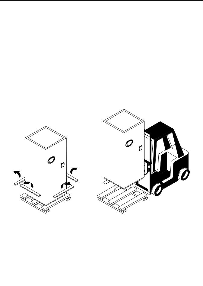
2.4.2Removal of Skid
•Remove the plywood skirting that keeps the skid and unit in place.
•Raise the Liebert Challenger 3000 off the skid. Emerson recommends using a fork lift (see Figure 1) or similar machine to ensure that the unit is lifted properly.
•Once the unit is raised, the skid can be removed.
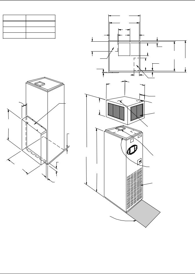
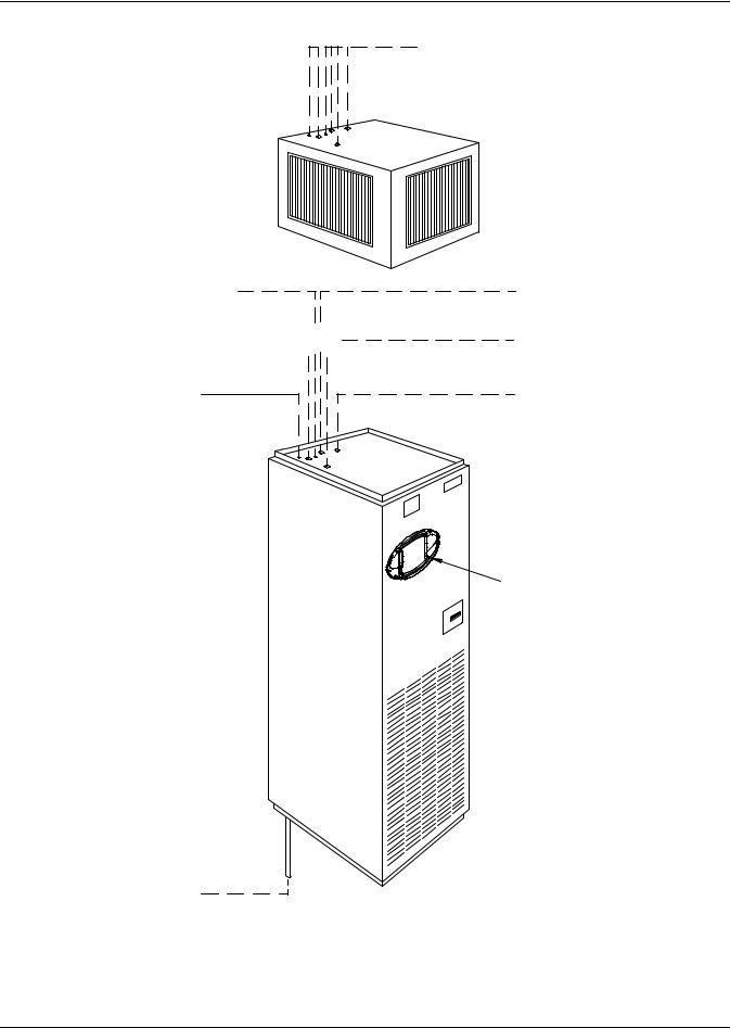
Figure 1 Removing the Liebert Challenger 3000 from skid
Raise unit with forklift Remove plywood skirting holding or similar machine. unit and skid in place.
Table 1 |
Unit net weight |
|
|
|
|
Model |
|
Lb. (kg) |
|
|
|
036E/035E |
|
535 (243) |
|
|
|
060E/059E |
|
545 (247) |
042A/040A |
|
615 (279) |
|
|
|
067A/065A |
|
670 (304) |
|
|
|
046WG/045WG |
700 (318) |
|
071WG/070WG |
750 (340) |
|
|
|
|
061G/058G |
|
785 (356) |
|
|
|
068C/072C |
|
545 (247) |
102C/101C |
|
555 (252) |
|
|
|
7 |
Liebert® Challenger 3000™ |
|
|
|
Installation (Applicable to all Models) |
|||
Figure 2 Upflow (BU) cabinet dimensions |
|
|
|
|
|
|
A |
|
32-1/2" |
|
|
|
|
|
(826mm) |
UNIT |
|
|||
STD 3 & 5T 11-3/4 (299mm) |
|
30-1/2" |
|
|||
|
TOP VIEW |
|
||||
|
(775mm) |
|
||||
Hi Static 3T 8-5/8 (219mm) |
|
A |
|
9-5/8" |
|
|
Hi Static 5T 11-3/4 (299mm) |
8-1/2" |
|
|
|
|
|
|
(216mm) |
|
|
(244mm) |
|
|
|
10-1/4" |
|
|
13" |
1-5/8" |
|
|
(260mm) |
|
|
(41mm) |
||
|
|
|
|
(330mm) |
|
30-1/2" |
|
|
|
|
|
|
|
|
Standard Piping Location |
|
|
|
(775mm) |
|
|
|
|
12-1/2" |
|
32-1/2" |
|
|
|
|
|
1-7/8" |
||
|
|
|
|
(826mm) |
||
|
|
|
|
(318mm) |
||
|
Projection of Display |
|
|
(48mm) |
|
|
|
|
|
|
|
||
|
Bezel 5/8" (16mm) |
5-1/2" (140mm) |
|
|
|
|
|
|
|
Standard Electrical Outlet |
|||
|
|
32-1/2" |
32-1/2" |
|
||
|
|
|
Location Through Unit |
|||
|
|
(826mm) |
(826mm) |
|
|
|
|
|
Overall |
Overall |
|
|
|
|
|
Dimension |
|
|
||
|
|
Dimension |
6-7/8" (175mm) |
|||
|
|
|
|
|
||
7-1/2" |
Filter Access |
18" |
Standard Electrical Outlet |
|
(191mm) |
||||
Through Top |
(457mm) |
Location Through Plenum |
||
|
||||
|
|
|
Air Discharge Grille |
|
29-3/4" |
|
|
|
|
(756mm) |
1" (25mm) |
|
Plenum available with: |
|
|
|
-2, 3 or 4 grilles. |
||
|
FRONT & |
|
-Solid sides with a 7/8" (22mm) |
|
|
SIDES |
|
||
|
|
duct flange on top. |
||
|
3/4" (19mm) |
|
||
|
|
|
||
|
REAR |
|
|
|
|
94" |
|
||
|
(2388mm) |
Blower Outlet with |
||
|
2-1/2" |
|
1" (25.4mm) Flange |
|
29" |
|
|
||
(737mm) |
(67mm) |
76" |
7/8" (22.2mm) Flange for |
|
|
|
(1930mm) |
Duct or Plenum Connection |
|
REAR VIEW |
1-3/4 " |
|
Return Air Louvers |
|
(rear return configuration) |
(44mm) |
|
|
|
Shaded area indicates a recommended |
|
|
clearance of 34" (864mm) for component |
|
|
access. Right side access suggested for |
|
|
GLYCOOL units. |
DPN000350 |
|
FRONT VIEW |
||
Rev. 1 |
||
(front return configuration) |
||
|
Liebert® Challenger 3000™ |
8 |
Installation (Applicable to all Models)
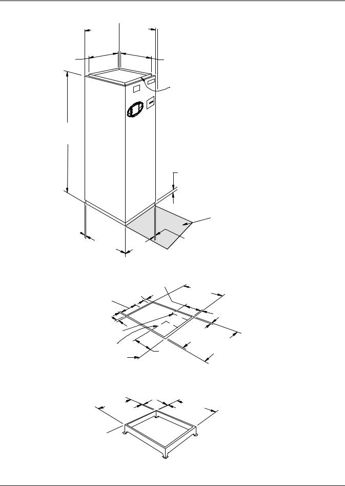
Figure 3 Downflow (BF) cabinet dimensions
30-1/2" (775mm)
76"
(1930mm)
1"  (25.4mm)
32-1/2"  32-1/2" (826mm) (826mm) Overall Overall Dimension Dimension

 Projection of Display
Bezel 5/8" (16mm)
30-1/2" (775mm)
Optional 1-5/8" (41mm)
Flange for Duct or
Plenum Connection
1" (25mm) FRONT & SIDES
3/4" (19mm) REAR
|
|
|
Shaded area indicates |
|
|
|
|
a recommended clearance of |
|
|
|
|
34” (864mm) for component |
|
30-1/2" |
|
1" |
access. Right side access |
|
30-1/2" |
suggested for GLYCOOL units |
|||
(25.4mm) |
||||
(775mm) |
(775mm) |
|
||
|
|
|
|
|
12" |
|
9" |
4" |
(305mm) |
30-1/2" |
(102mm) |
|
(775mm) |
|
(229mm) |
|
||
|
|
|
|
1" (25.4mm) |
|
|
1" |
|
|
(25.4mm) |
Standard Electrical Location |
|
28-1/2" |
|
Standard Piping |
|
(724mm) 30-1/2" |
|
Location |
Floor |
8" |
(775mm) |
|
(203mm) |
|
|
|
Level |
|
|
|
|
|
|
FLOOR CUTOUT DIMENSIONS
1" |
|
|
(25.4mm) |
30-1/2" |
|
30-1/2" |
(775mm) |
|
(775mm) |
||
|
See Specification 
Sheet for Floor Stand
Height Ordered.
OPTIONAL FLOOR STAND DIMENSIONAL DATA
DPN000351
Rev. 1
9 |
Liebert® Challenger 3000™ |

Installation (Applicable to all Models)
2.5Piping Considerations
All piping below the elevated floor must be located so that it offers the least resistance to air flow. Careful planning of the piping layout under the raised floor is required to prevent the air flow from being blocked. When installing piping on the subfloor, it is recommended that the pipes be mounted in a horizontal plane rather than stacked one above the other. Whenever possible, the pipes should be run parallel to the air flow.
Condensate pumps for downflow units are shipped separately to be field-installed under the raised floor. Pump height is 11 in. (279mm).
2.5.1Drain Line
A 3/4" (19.1mm) female pipe thread (FPT) connection is provided for the evaporator coil condensate drain. This drain line also drains the humidifier, if applicable. The drain line must be located so it will not be exposed to freezing temperatures. The drain should be at least the full size of the drain connection and pitched a minimum of 1/8" per ft. (11mm per meter).
NOTICE
Risk of water backing up in the evaporator coil drain line. Can cause the drain pan to overflow, resulting in building and equipment damage.
Do not install an external trap in the drain line of units without a condensate pump. This line already has a factory-installed trap inside the cabinet.
NOTICE
Risk of drain line damage. Can cause water leaks resulting in furniture, equipment and building damage.
This line may contain boiling water. Select appropriate drain system materials.
Units with a condensate pump will require a field-supplied trap downstream from the pump. The drain line must comply with all applicable national, state and local plumbing codes.
Table 2 |
Piping connection size |
|
|
|
|
|
|
|
|
|
|
Air-Cooled Unit Connection Sizes—in. |
|
|
|
||
Model No. BF/BU |
Liquid Line O.D. Copper |
Hot Gas Line OD Copper |
|
||
|
(50 Hz) |
L |
HG |
|
|
|
042A (040A) |
3/8 |
5/8 |
|
|
|
067A (065A) |
1/2 |
7/8 |
|
|
Split System Fan Coil Unit |
Connection Sizes—in. |
|
|
|
|
Model No. BF/BU (50 Hz) |
Liquid Line |
Suction Line |
|
||
|
|
L |
SC |
|
|
|
036E (035E) |
5/8 - 18 Female (#6 QC) |
1-1/8 - 12 Female (#11 QC) |
|
|
|
060E (059E) |
1/2 OD Cu |
1-1/8 OD Cu |
|
|
All Units: Connection Sizes—in. |
|
|
|
||
|
Humidifier Line |
Condensate |
Condensate Pump Line |
Hot Water Reheat |
|
|
OD Copper |
Drain Line |
OD Copper |
OD Copper |
|
|
H |
C |
P |
|
|
|
|
|
|
Supply |
Return |
|
1/4 |
3/4 FPT |
1/2 |
HWS |
HWR |
|
|
|
|
5/8 |
5/8 |
Water/Glycol-Cooled Unit |
Connection Sizes—inches |
|
|
|
|
Model No. BF/BU |
Supply Line |
Return Line |
|
||
|
(50 Hz) |
S |
R |
|
|
046WG (045WG) |
7/8 |
7/8 |
|
|
|
071WG (070WG) |
1-1/8 |
1-1/8 |
|
|
|
GLYCOOL Unit Connection |
Sizes —in. |
|
|
|
|
Model No. BE/BK |
Supply Line |
Return Line |
|
||
|
(50 Hz) |
S |
R |
|
|
|
061G (058G) |
1-1/8 |
1-1/8 |
|
|
Liebert® Challenger 3000™ |
10 |
|
|
|
|
Installation (Applicable to all Models) |
|
|
Table 2 |
Piping connection size (continued) |
|
|
|
|
|
|
|
|
|
|
Chilled Water Unit Connection Sizes—in. |
|
|
||
|
Model No. BF/BU |
Supply Line |
Return Line |
|
|
|
|
(50 Hz) |
CWS |
CWR |
|
|
|
068C (072C) |
1-1/8 |
1-1/8 |
|
|
|
102C (101C) |
1-1/8 |
1-1/8 |
|
Figure 4 Piping connections for air-cooled units - Downflow models
Liebert iCOM
Control Panel
Condensate Drain 3/4" FPT Field-pitch a minimum of 1/8" (3.2mm) per foot (305mm). The drain line must comply with all applicable codes.
Humidifier Water Supply Line
1/4" OD CU
PIPING OUTLET LOCATIONS
(See Cabinet and Floor Planning Dimensional Data for Piping Opening Sizes.)
Liquid Refrigerant Line
3/8" OD CU on Models BF042A/BF040A 1/2" OD CU on Models BF067A/BF065A
Hot Gas Refrigerant Line
5/8" OD CU on Models BF042A/BF040A 7/8" OD CU on Models BF067A/BF065A
Hot Water Return
5/8" OD CU (optional)
Hot Water Supply
5/8" OD CU (optional)
DPN000353
Rev. 1
11 |
Liebert® Challenger 3000™ |
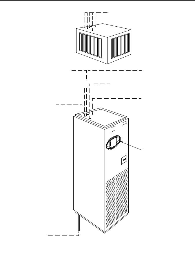
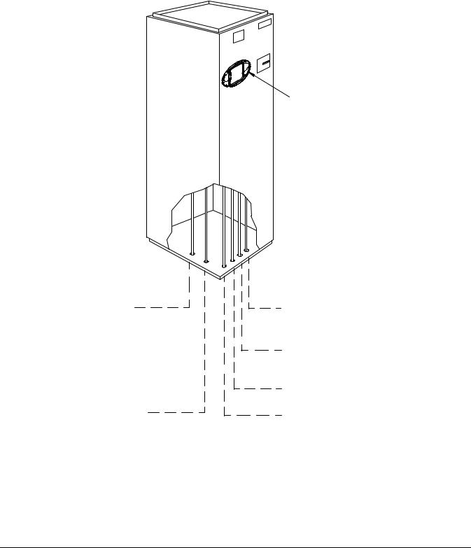
Figure 5 Piping connections for air-cooled units - Upflow models
Humidifier Water Supply Line
1/4" OD CU
Hot Gas Refrigerant Line 


 5/8" OD CU on Models BU042A/BU040A
7/8" OD CU on Models BU067A/BU065A
Condensate Pump Line 1/2" OD CU
Used only if optional condensate pump is ordered.
Condensate Drain 3/4" FPT
Field pitch a min. of 1/8" (3.2mm) per ft. (305mm). Units without a condensate pump have a factory-supplied trap in the unit, so
do not field-install a trap in the drain line. Units with a condensate pump will require a field-supplied trap downstream from the pump. The
drain line must comply with all applicable national, state and local plumbing codes. (If condensate pump is ordered piping is out top of unit).
Liebert® Challenger 3000™ |
12 |
Installation (Applicable to all Models)
Figure 6 Piping connections for split system fan coil units - Downflow models
Liebert iCOM
Control
Condensate Drain 3/4" FPT
Field pitch a minimum
of 1/8" (3.2mm) per ft. (305mm). The drainline must comply
with all applicable codes.
Humidifier Water Supply Line
1/4" OD CU
PIPING OUTLET LOCATIONS (See Cabinet and Floor Planning Dimensional Data for Piping Opening Sizes.)
Liquid Refrigerant Line
#6 Quick Connect on Models BF036E/BF035E 1/2" OD CU on Models BF060E/BF059E
Suction Refrigerant Line
#11 Quick Connect on Models BF036E/BF035E 1-1/8" OD CU on Models BF060E/BF059E
Hot Water Return
5/8" OD CU (optional)
Hot Water Supply
5/8" OD CU (optional)
DPN000376
Rev. 1
13 |
Liebert® Challenger 3000™ |
Installation (Applicable to all Models)
Figure 7 Piping connections for split system fan coil units - Upflow models
Humidifier Water Supply Line
1/4" OD CU
Suction Refrigerant Line #11 Quick Connect on Models BU036E/BU035E
1 1/8" OD CU on Models BU060E/BU059E
Condensate Pump Line 1/2" OD CU; used only
if optional condensate pump is ordered.
Piping outlet locations through the plenum are the same as the unit. See below for descriptions and connection sizes.
Hot Water Return
5/8" OD CU (optional)
Liquid Refrigerant Line
#6 Quick Connect on Models BU036E/BU035E 1/2" OD CU on Models BU060E/BU059E
Hot Water Supply 5/8" OD CU (optional)
iCOM Control
Panel
Condensate Drain; 3/4" FPT
Field pitch a min. of 1/8" (3.2mm) per ft. (305mm). Units without a condensate pump have a factory-supplied trap in the unit, so
do not field-install a trap in the drain line. Units with a condensate pump will require a field-supplied trap downstream from the pump. The
drain line must comply with all applicable national, state and local plumbing codes. (If condensate pump is ordered piping is out top of unit).
PIPING OUTLET LOCATIONS (See Cabinet and Floor Planning Dimensional Data for Piping Opening Sizes.)
DPN000375
Rev. 1
Liebert® Challenger 3000™ |
14 |
Installation (Applicable to all Models)
Figure 8 Piping connections for water/glycol and GLYCOOL units - Downflow models
iCOM Control
Panel
Condensate Drain 3/4" FPT
Field pitch a minimum
of 1/8" (3.2mm) per ft. (305mm). The drain line must comply with all applicable codes
Humidifier Water Supply Line
1/4" OD CU
Condenser Supply Line
7/8" OD CU on Models BF046WG/BF045WG 1-1/8" OD CU on Models BF071WG/BF070WG
Condenser Return Line
7/8" OD CU on Models BF046WG/BF045WG 1-1/8" OD CU on Models BF071WG/BF070WG
Hot Water Return
5/8" OD CU (optional)
Hot Water Supply
5/8" OD CU (optional)
PIPING OUTLET LOCATIONS (See Cabinet and Floor Planning Dimensional Data for Piping Opening Sizes.)
DPN000364
Rev. 1
15 |
Liebert® Challenger 3000™ |
Installation (Applicable to all Models)
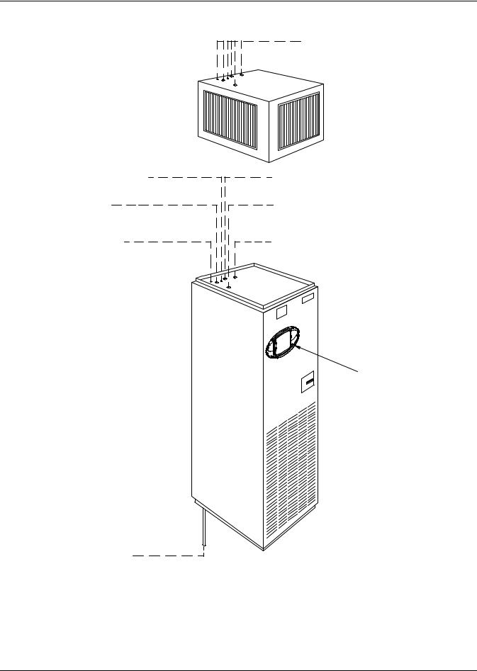
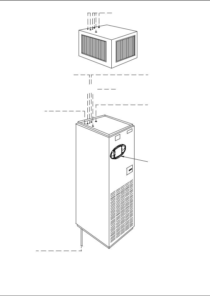
Figure 9 Piping connections for water/glycol and GLYCOOL units - Upflow models
Humidifier Water Supply Line
1/4" OD CU
Condenser Return Line 


 7/8" OD CU on Models BU046WG/BU045WG 1-1/8" OD CU on Models BU071WG/BU070WG
Condensate Pump Line 1/2" OD CU
Used only if optional condensate pump is ordered.
Condensate Drain 3/4" FPT
Field pitch a min. of 1/8" (3.2mm) per ft. (305mm). Units without a condensate pump have a factory-supplied trap in the unit, so
do not field-install a trap in the drain line. Units with a condensate pump will require a field-supplied trap downstream from the pump. The
drain line must comply with all applicable national, state and local plumbing codes. (If condensate pump is ordered piping is out top of unit).
DPN000363
Rev. 1
Liebert® Challenger 3000™ |
16 |
Installation (Applicable to all Models)
Figure 10 Piping connections for chilled water self-contained units - Downflow models
Liebert iCOM
Control
Condensate Drain 3/4" FPT
Field pitch a minimum
of 1/8" (3.2mm) per ft. (305mm). The drain line must comply with all applicable codes.
Humidifier Water Supply Line
1/4" OD CU
PIPING OUTLET LOCATIONS (See Cabinet and Floor Planning Dimensional Data for Piping Opening Sizes.)
Chilled Water Supply Line
1-1/8" OD CU
Chilled Water Return Line
1-1/8" OD CU
Hot Water Return
5/8" OD CU (optional)
Hot Water Supply
5/8" OD CU (optional)
DPN000371
Rev. 1
17 |
Liebert® Challenger 3000™ |
Installation (Applicable to all Models)
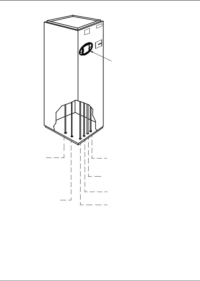
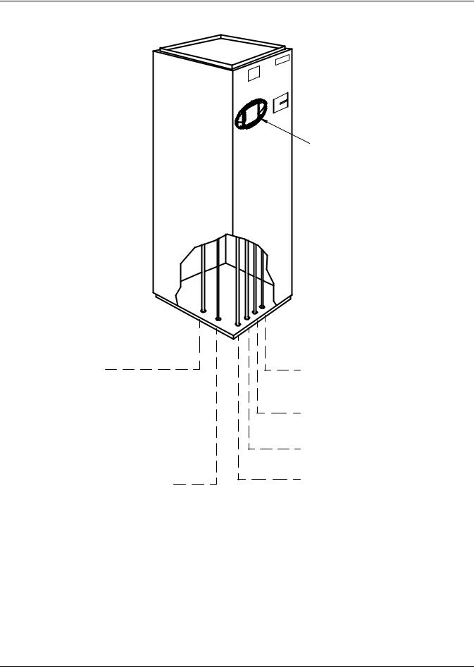
Figure 11 Piping connections for chilled water self-contained units - Upflow models
Piping outlet locations through
the plenum are the same as the unit. See below for descriptions and connection sizes.
Humidifier Water Supply Line
1/4" OD CU
Chilled Water Supply Line 


1-1/8" OD CU
Condensate Pump Line
1/2" OD CU; used only if optional condensate pump is ordered.
Condensate Drain 3/4" FPT
Field pitch a min. of 1/8" (3.2mm) per ft. (305mm). Units without a condensate pump have a factory-supplied trap in the unit, so
do not field-install a trap in the drain line. Units with a condensate pump will require a field-supplied trap downstream from the pump. The
drain line must comply with all applicable national, state and local plumbing codes. (If condensate pump is ordered piping is out top of unit).
Hot Water Return
5/8" OD CU (optional)
Chilled Water Return Line
1-1/8" OD CU
Hot Water Supply
5/8" OD CU (optional)
iCOM Control
Panel
PIPING OUTLET LOCATIONS (See Cabinet and Floor Planning Dimensional Data for Piping Opening Sizes.)
DPN000370
Rev. 1
Liebert® Challenger 3000™ |
18 |
Installation (Applicable to all Models)
2.5.2Humidifier Supply Water—Optional Infrared
•1/4" supply line; maximum water pressure is 150 psi (1034kPa)
•Size humidifier supply line for 1 gpm (3.8 l/m), with a minimum water pressure of 20 psi (138kPa)
•Do not supply de-ionized water to the humidifier
2.6Facility Fluid and Piping Maintenance
Facility water and glycol quality remain a requirement throughout the life of the piping system. Fluid and piping system maintenance schedules must be established and performed. A local fluid maintenance program must be established that will evaluate fluid chemistry and apply necessary treatment. A periodic leak inspection of facility and unit fluid piping is recommended. Refer to 5.4 - Glycol Piping.
2.7Electrical Connections
Three-phase electrical service is required for all models in either 208, 230, 460, or 575 V, 60 Hz; or 200, 230, or 380/415 V, 50 Hz. Electrical service shall conform to national and local electrical codes. Refer to equipment nameplate regarding wire size and circuit protection requirements. Refer to electrical schematic when making connections.
A manual electrical disconnect switch should be installed within 5 feet (1.6 m) of the unit in accordance with codes, or a factory-supplied disconnect switch may be factory mounted within the unit accessible from the exterior.
! WARNING
Risk of electric shock. Can cause injury or death.
Potentially lethal voltages exist within this equipment during operation. Observe all cautions and warnings on unit and in this manual.
The Liebert iCOM® microprocessor does not isolate power from the unit, even in the “Unit Off” mode. The only way to ensure that there is NO voltage inside the unit is to install and open a remote disconnect switch and verify the absence of electrical power with a voltmeter. Refer to unit electrical schematic.
! WARNING
Risk of loose electrical wiring connections. Can cause overheating of wire, smoke and fire resulting in building and/or equipment damage, injury or death.
Use copper wire only and verify that all connections are tight.
NOTICE
Risk of improper scroll compressor phase sequencing. Could cause poor performance and compressor damage.
Three-phase power must be connected to the unit line voltage terminals in the proper sequence so that the scroll compressor rotates in the proper direction. Rotation in the wrong direction will result in poor performance and compressor damage. Use a phase sequence and motor rotation sensor to ensure that the three-phase power is correctly connected and the compressor is rotating properly.
19 |
Liebert® Challenger 3000™ |
Installation (Applicable to all Models)
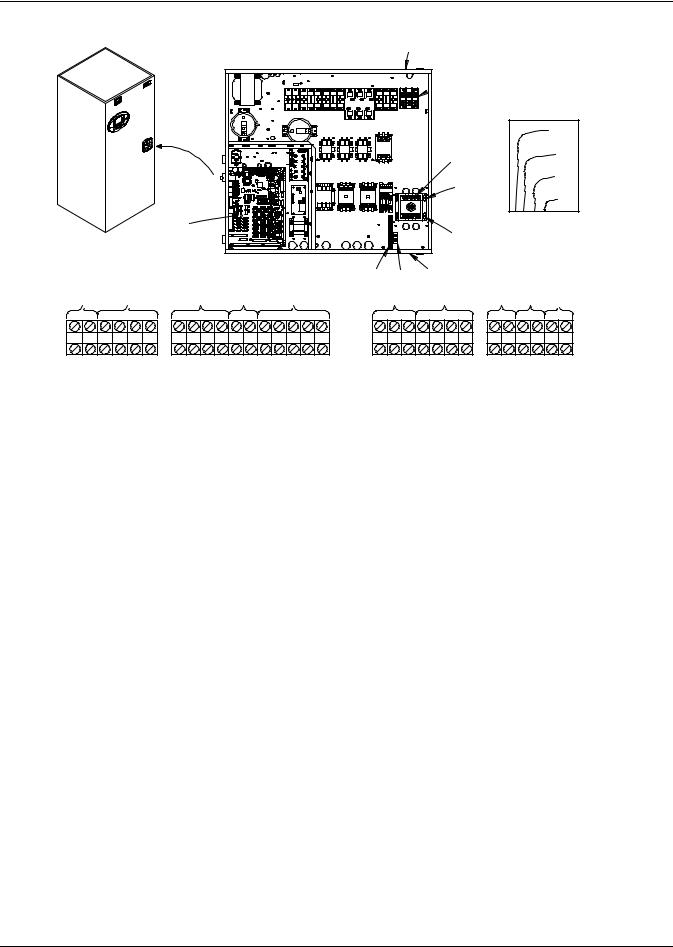
Figure 12 Electrical connections
1
Electrical Handy Box *
 2 (Factory-Installed With Cover)
14
|
|
|
|
|
|
|
|
|
73 |
|
|
|
|
|
|
3 |
|
|
72 |
|
|
|
|
|
|
4 |
|
|
71 |
|
|
|
|
|
|
|
|
70 |
|
|
|
|
|
|
|
|
|
|
|
|
|
8 |
|
|
|
5 |
|
|
|
Terminal Block |
|
|
|
|
|
|
|
||
|
|
|
|
|
|
|
|
||
(for Customer Connectons |
|
7 |
6 |
1 |
|
|
|
||
|
|
|
|
|
|
|
|||
13 |
13 |
9 |
9 |
10 |
12 |
11 |
15 |
16 |
17 |
75 76 94 95 96 97 |
37C38C37B38B 37 38 24 50 51 55 56 |
91 92 93 12 |
34 |
82 83 84 85 88 89 |
DPN000354
Rev. 2
2.7.1Electrical Field Connections for Liebert Challenger 3000 Models
Source: DPN00354, Rev. 2
1.Electric conduit knockouts on top and bottom of electric box. Knockout size 1-3/4" (44.5mm).
2.Three-phase connection. Electric service connection terminals when factory disconnect is NOT supplied.
3.Three-phase connection. Electric service connection terminals when factory disconnect switch is supplied.
4.Factory-installed disconnect switch. (Optional).
5.Three-phase electric service field-supplied.
6.Earth ground connection (50/60Hz). Connection terminal for field-supplied earth grounding wire.
7.Earth ground bar (50Hz only). Connection terminals with factory ground from each high voltage component for field-supplied earth grounding wire.
8.Control and monitoring section of electric box.
9.Remote unit shutdown. Replace existing jumper between Terminals 37 + 38 with normally closed switch having a minimum 75VA, 24VAC rating. Use field-supplied Class 1 wiring. Two additional contact pairs available as an option (labeled as 37B & 38B, 37C & 38C). Replace existing jumper for appropriate pair as done for 37 & 38.
10.Special alarm connections. Field-supplied 24V Class 1 wiring for special alarm. Connection made by adding normally open contacts between terminals 24 + 50. Special alarm connections may be factory-wired or field-wired. See schematic for factory-wired special alarms. For field-wired special alarms, use 24V Class 1 wiring to connect normally open contacts between Terminals 24 & 50, 24 & 51, 24 & 55, or 24 & 56.
11.Remote condensing unit connection. Field-supplied 24V Class 1 wiring to remote condensing unit Terminals 1, 2, 3, & 4 from (R2) relay (split system only).
12.Smoke detector alarm connections. Field-supplied 24V Class 1 wiring to remote alarm circuits. Factory-wired contacts from optional smoke detector are #91-comm., #92-NO, and #93-NC.
13.Common alarm connection. Field-supplied 24V. Class 1 wiring to common alarm Terminals 75 + 76 (and optional 94 + 95, and 96 + 97), which are factory-connected to common alarm relay (R3).
Liebert® Challenger 3000™ |
20 |
Installation (Applicable to all Models)
14.Heat rejection connection. Field-supplied 24V Class 1 wiring to interlock heat rejection from pigtails 70 + 71, which are factory-connected to compressor side switch (self-contained units only) or to GLYCOOL relay (K11, GLYCOOL units only). On Dual Cool units only, pigtails 72 + 73 connect auxiliary cooling source to GLYCOOL relay K11.
15.Reheat and Humidifier Lockout. Optional emergency power lockout of reheat and/or humidifier: connections provided for remote 24V AC source.
16.Main Fan Auxiliary Switch. Optional main fan auxiliary side switch. Terminals located in field wiring compartment for remote indication that the evaporator fan motor/unit is On. Field to connect 24V maximum.
17.Optional Condensate Alarm (Dual Float Condensate Pump only). Relay terminals located in field wiring compartment for remote indication.
Refer to specification sheet for full load amp. and wire size amp. ratings.
Figure 13 Electrical field connections for Liebert iCOM®
23 |
24 |
22 |
21 |
|
|
20 19 |
25 |
DPN001733
Rev. 0
Upflow Models with Liebert iCOM


 22
22
|
24 |
|
23 |
20 |
25 |
|
19 |
Downflow Models with Liebert iCOM
DPN001734 |
Rev. 0 |
18.Network Cable “C” Connection. Eight-wire Ethernet cable from U2U networking switch.
19.Network Cable “D” connection. Eight-wire Ethernet cable from U2U networking switch. Cable “D” connection supplied on units with large Liebert iCOM display only.
20.Opening for Field Wiring. Suggested entry point for all field wiring to unit. Hole size Ø2.5" (63.5mm).
21.Loose Wire Ties. To secure field-supplied network cables. Tighten after all field-supplied wires have been installed.
22.Vacant Liebert IntelliSlot®. May contain optional Liebert IntelliSlot cards.
23.Populated Liebert IntelliSlot. Optional Liebert IntelliSlot cards may be placed in either of the two supplied Liebert IntelliSlot locations.
24.Remote Temperature / Humidity Sensor Connection. Six-wire CAN cable supplied with optional remote T/H sensor
21 |
Liebert® Challenger 3000™ |
Loading...