


 Loading...
Reference Manual
00809-0400-4728, Rev AA
June 2011
Rosemount 644 Temperature Transmitter with FOUNDATION™ fieldbus
www.rosemount.com

Rosemount 644
Reference Manual
00809-0400-4728, Rev AA
June 2011
Table of Contents
SECTION 1
Introduction
SECTION 2
Installation
SECTION 3
Configuration
Safety Messages . . . . . . . . . . . . . . . . . . . . . . . . . . . . . . . . . . . . . . . . . 1-1
Warnings . . . . . . . . . . . . . . . . . . . . . . . . . . . . . . . . . . . . . . . . . . . . 1-1
Overview . . . . . . . . . . . . . . . . . . . . . . . . . . . . . . . . . . . . . . . . . . . . . . . 1-2
Manual . . . . . . . . . . . . . . . . . . . . . . . . . . . . . . . . . . . . . . . . . . . . . . 1-2
Transmitter . . . . . . . . . . . . . . . . . . . . . . . . . . . . . . . . . . . . . . . . . . . 1-2
Considerations. . . . . . . . . . . . . . . . . . . . . . . . . . . . . . . . . . . . . . . . . . . 1-3
General. . . . . . . . . . . . . . . . . . . . . . . . . . . . . . . . . . . . . . . . . . . . . . 1-3
Commissioning . . . . . . . . . . . . . . . . . . . . . . . . . . . . . . . . . . . . . . . . 1-3
Mechanical . . . . . . . . . . . . . . . . . . . . . . . . . . . . . . . . . . . . . . . . . . . 1-3
Electrical . . . . . . . . . . . . . . . . . . . . . . . . . . . . . . . . . . . . . . . . . . . . . 1-3
Environmental. . . . . . . . . . . . . . . . . . . . . . . . . . . . . . . . . . . . . . . . . 1-3
Return of Materials . . . . . . . . . . . . . . . . . . . . . . . . . . . . . . . . . . . . . . . 1-4
Product Recycling/Disposal . . . . . . . . . . . . . . . . . . . . . . . . . . . . . . . . . 1-4
Safety Messages . . . . . . . . . . . . . . . . . . . . . . . . . . . . . . . . . . . . . . . . . 2-1
Warnings . . . . . . . . . . . . . . . . . . . . . . . . . . . . . . . . . . . . . . . . . . . . 2-1
Mounting . . . . . . . . . . . . . . . . . . . . . . . . . . . . . . . . . . . . . . . . . . . . . . . 2-3
Installation . . . . . . . . . . . . . . . . . . . . . . . . . . . . . . . . . . . . . . . . . . . . . . 2-4
Typical European Installation . . . . . . . . . . . . . . . . . . . . . . . . . . . . . 2-4
Typical North American Installation . . . . . . . . . . . . . . . . . . . . . . . . 2-5
LCD Display Installation . . . . . . . . . . . . . . . . . . . . . . . . . . . . . . . . . 2-6
Wiring. . . . . . . . . . . . . . . . . . . . . . . . . . . . . . . . . . . . . . . . . . . . . . . . . . 2-7
Sensor Connections . . . . . . . . . . . . . . . . . . . . . . . . . . . . . . . . . . . . 2-8
Power Supply. . . . . . . . . . . . . . . . . . . . . . . . . . . . . . . . . . . . . . . . . . . 2-11
Ground the Transmitter . . . . . . . . . . . . . . . . . . . . . . . . . . . . . . . . 2-11
Overview . . . . . . . . . . . . . . . . . . . . . . . . . . . . . . . . . . . . . . . . . . . . . . . 3-1 Safety Messages . . . . . . . . . . . . . . . . . . . . . . . . . . . . . . . . . . . . . . . . . 3-1 Warnings . . . . . . . . . . . . . . . . . . . . . . . . . . . . . . . . . . . . . . . . . . . . 3-1 General Block Information . . . . . . . . . . . . . . . . . . . . . . . . . . . . . . . . . . 3-2 Device Description . . . . . . . . . . . . . . . . . . . . . . . . . . . . . . . . . . . . . 3-2 Node Address. . . . . . . . . . . . . . . . . . . . . . . . . . . . . . . . . . . . . . . . . 3-2 Modes. . . . . . . . . . . . . . . . . . . . . . . . . . . . . . . . . . . . . . . . . . . . . . . 3-2 Link Active Scheduler . . . . . . . . . . . . . . . . . . . . . . . . . . . . . . . . . . . 3-3 Block Installation. . . . . . . . . . . . . . . . . . . . . . . . . . . . . . . . . . . . . . . 3-3 Capabilities . . . . . . . . . . . . . . . . . . . . . . . . . . . . . . . . . . . . . . . . . . . 3-4 Foundation fieldbus function blocks. . . . . . . . . . . . . . . . . . . . . . . . . . . 3-4 Resource Block . . . . . . . . . . . . . . . . . . . . . . . . . . . . . . . . . . . . . . . 3-5 Sensor Transducer Block . . . . . . . . . . . . . . . . . . . . . . . . . . . . . . . . 3-9 Analog Input (AI) Function Block . . . . . . . . . . . . . . . . . . . . . . . . . . 3-9 LCD Transducer Block . . . . . . . . . . . . . . . . . . . . . . . . . . . . . . . . . 3-14 Operation and Maintenance . . . . . . . . . . . . . . . . . . . . . . . . . . . . . . . 3-15 Overview. . . . . . . . . . . . . . . . . . . . . . . . . . . . . . . . . . . . . . . . . . . . 3-15 Troubleshooting Guides . . . . . . . . . . . . . . . . . . . . . . . . . . . . . . . . 3-16 Sensor Transducer Block . . . . . . . . . . . . . . . . . . . . . . . . . . . . . . . 3-18 Analog Input (AI) Function Block . . . . . . . . . . . . . . . . . . . . . . . . . 3-21 Resource Block . . . . . . . . . . . . . . . . . . . . . . . . . . . . . . . . . . . . . . 3-23 LCD Transducer block . . . . . . . . . . . . . . . . . . . . . . . . . . . . . . . . . 3-24
TOC-1

Reference Manual
00809-0400-4728, Rev AA
June 2011
Rosemount 644
APPENDIX A
Specifications and
Reference Data
APPENDIX B
Product
Certifications
APPENDIX C Foundation fieldbus Block Information
Specifications. . . . . . . . . . . . . . . . . . . . . . . . . . . . . . . . . . . . . . . . . . . .A-1
Functional . . . . . . . . . . . . . . . . . . . . . . . . . . . . . . . . . . . . . . . . . . . .A-1
Physical . . . . . . . . . . . . . . . . . . . . . . . . . . . . . . . . . . . . . . . . . . . . .A-2
Performance . . . . . . . . . . . . . . . . . . . . . . . . . . . . . . . . . . . . . . . . . .A-3
Foundation Fieldbus Specifications . . . . . . . . . . . . . . . . . . . . . . . . . . .A-4
Dimensional Drawings . . . . . . . . . . . . . . . . . . . . . . . . . . . . . . . . . . . . .A-9
Ordering Information . . . . . . . . . . . . . . . . . . . . . . . . . . . . . . . . . . . . .A-12
Tagging. . . . . . . . . . . . . . . . . . . . . . . . . . . . . . . . . . . . . . . . . . . . .A-14
Considerations . . . . . . . . . . . . . . . . . . . . . . . . . . . . . . . . . . . . . . .A-14
Configuration . . . . . . . . . . . . . . . . . . . . . . . . . . . . . . . . . . . . . . . .A-15
Approved Manufacturing Locations . . . . . . . . . . . . . . . . . . . . . . . . . . .B-1
European Union Directive Information . . . . . . . . . . . . . . . . . . . . . . . . .B-1
Hazardous Locations Certificates . . . . . . . . . . . . . . . . . . . . . . . . . . . .B-2
Rosemount 644 with Foundation fieldbus. . . . . . . . . . . . . . . . . . . .B-2
North American Certifications . . . . . . . . . . . . . . . . . . . . . . . . . . . . .B-2
European Certifications . . . . . . . . . . . . . . . . . . . . . . . . . . . . . . . . .B-3
IECEx Certifications . . . . . . . . . . . . . . . . . . . . . . . . . . . . . . . . . . . .B-4
Japanese Certifications . . . . . . . . . . . . . . . . . . . . . . . . . . . . . . . . .B-6
Combination Approvals. . . . . . . . . . . . . . . . . . . . . . . . . . . . . . . . . .B-6
Russian GOST Certifications . . . . . . . . . . . . . . . . . . . . . . . . . . . . .B-6
Kazakhstan GOST . . . . . . . . . . . . . . . . . . . . . . . . . . . . . . . . . . . . .B-6
Ukraine GOST . . . . . . . . . . . . . . . . . . . . . . . . . . . . . . . . . . . . . . . .B-6
Installation Drawings . . . . . . . . . . . . . . . . . . . . . . . . . . . . . . . . . . . . . .B-7
Basic Setup . . . . . . . . . . . . . . . . . . . . . . . . . . . . . . . . . . . . . . . . . . . . .C-1
Resource Block . . . . . . . . . . . . . . . . . . . . . . . . . . . . . . . . . . . . . . . . . .C-1
Parameters and Descriptions . . . . . . . . . . . . . . . . . . . . . . . . . . . . .C-2
Sensor Transducer Block. . . . . . . . . . . . . . . . . . . . . . . . . . . . . . . . . . .C-5
Parameters and Descriptions . . . . . . . . . . . . . . . . . . . . . . . . . . . .C-5
Analog Input (AI) Function Block . . . . . . . . . . . . . . . . . . . . . . . . . . . . .C-8
AI Parameter Table. . . . . . . . . . . . . . . . . . . . . . . . . . . . . . . . . . . . .C-9
LCD Transducer Block. . . . . . . . . . . . . . . . . . . . . . . . . . . . . . . . . . . .C-11
PID Block . . . . . . . . . . . . . . . . . . . . . . . . . . . . . . . . . . . . . . . . . . . . . .C-12
TOC-2

Reference Manual
00809-0400-4728, Rev AA
June 2011
Rosemount 644
Rosemount 644
Temperature Transmitters
Rosemount 644 Hardware Revision |
9 |
FOUNDATION™ Fieldbus Device Revision |
2 |
Device Descriptor Revision |
1 |
NOTICE
Read this manual before working with the product. For personal and system safety, and for optimum product performance, make sure to thoroughly understand the contents before installing, using, or maintaining this product.
The United States has two toll-free assistance numbers and one international number.
Customer Central
1-800-999-9307 (7:00 a.m. to 7:00 p.m. CST)
National Response Center
1-800-654-7768 (24 hours a day) Equipment service needs
International
1-(952)-906-8888
The products described in this document are NOT designed for nuclear-qualified applications.
Using non-nuclear qualified products in applications that require nuclear-qualified hardware or products may cause inaccurate readings.
For information on Rosemount nuclear-qualified products, contact a Emerson Process Management Sales Representative.
www.rosemount.com

Reference Manual
00809-0400-4728, Rev AA
June 2011
Rosemount 644
Section 1 |
Introduction |
SAFETY MESSAGES
Warnings
Safety Messages . . . . . . . . . . . . . . . . . . . . . . . . . . . . . . . . . page 1-1 Overview . . . . . . . . . . . . . . . . . . . . . . . . . . . . . . . . . . . . . . . page 1-2 Considerations . . . . . . . . . . . . . . . . . . . . . . . . . . . . . . . . . . page 1-3 Return of Materials . . . . . . . . . . . . . . . . . . . . . . . . . . . . . . . page 1-4
Instructions and procedures in this section may require special precautions to ensure the safety of the personnel performing the operations. Information that potentially raises safety issues is indicated by a warning symbol ( ). Please refer to the following safety messages before performing an operation preceded by this symbol.
Failure to follow these installation guidelines could result in death or serious injury.
•Make sure only qualified personnel perform the installation.
Explosions could result in death or serious injury.
•Do not remove the connection head cover in explosive atmospheres when the circuit is live.
•Before connecting FOUNDATION fieldbus in an explosive atmosphere, make sure the instruments in the loop are installed in accordance with intrinsically safe or non-intrinsic field wiring practices.
•Verify that the operating atmosphere of the transmitter is consistent with the appropriate hazardous locations certifications.
•All connection head covers must be fully engaged to meet explosion-proof requirements.
Process leaks could result in death or serious injury.
•Do not remove the thermowell while in operation.
•Install and tighten thermowells and sensors before applying pressure.
Electrical shock could cause death or serious injury.
•Use extreme caution when making contact with the leads and terminals.
www.rosemount.com

Rosemount 644
Reference Manual
00809-0400-4728, Rev AA
June 2011
OVERVIEW
Manual |
This manual is designed to assist in the installation, operation, and |
|
maintenance of Rosemount 644 head mount and 644 rail mount. |
|
Section 1: Introduction |
|
• Transmitter and Manual Overview |
|
|
• |
Considerations |
|
• |
Return of Material |
|
Section 2: Installation |
|
|
• |
Mounting |
|
• |
Installation |
|
• |
Wiring |
|
• |
Power Supply |
|
• |
Commissioning |
|
Section 3: Configuration |
|
|
• |
Calibration |
|
• |
Hardware Maintenance |
|
• |
Diagnostic Messaging |
|
Appendix A: Specifications and Reference Data |
|
|
• |
Specifications |
|
• |
Dimensional Drawings |
|
• |
Ordering Information |
|
• Biotechnology, Pharmaceutical Industries, and Sanitary Applications |
|
|
Appendix B: Product Certifications |
|
|
• |
Product Certifications |
|
• |
Installation Drawings |
|
Appendix C: Foundation fieldbus Block Information |
|
|
• Information regarding the Function Blocks |
|
Transmitter |
Features of the Rosemount 644 include: |
|
|
• Accepts inputs from a wide variety of sensors |
|
|
• Configuration using FOUNDATION fieldbus |
|
• Electronics that are completely encapsulated in epoxy and enclosed in a metal housing, making the transmitter extremely durable and ensuring long-term reliability
• A compact size and two housing options allowing mounting flexibility for the control room or the field
1-2

Reference Manual
00809-0400-4728, Rev AA
June 2011
Rosemount 644
Refer to the following literature for a full range of compatible connection heads, sensors, and thermowells provided by Emerson Process Management.
|
• Temperature Sensors and Assemblies Product Data Sheet, Volume 1 |
|
(document number 00813-0100-2654) |
|
• Temperature Sensors and Assemblies Product Data Sheet, Volume 2 |
|
(document number 00813-0200-2654) |
CONSIDERATIONS |
|
General |
Electrical temperature sensors such as RTDs and thermocouples produce |
|
low-level signals proportional to their sensed temperature. The 644 converts |
|
the low-level sensor signal to a standard 4–20 mA dc, or digital FOUNDATION |
|
fieldbus signal that is relatively insensitive to lead length and electrical noise. |
|
This signal is then transmitted to the control room via two wires. |
Commissioning |
The transmitter can be commissioned before or after installation. It may be |
|
useful to commission it on the bench, before installation, to ensure proper |
|
operation and to become familiar with its functionality. Make sure the |
|
instruments in the loop are installed in accordance with intrinsically safe, |
|
FISCO, or non-incendive field wiring practices. |
Mechanical |
Location |
|
When choosing an installation location and position, take into account the |
|
need for access to the transmitter. |
|
Special Mounting |
|
Special mounting hardware is available for mounting a 644 head mount |
|
transmitter to a DIN rail or assembling a new 644 head mount to an existing |
|
threaded sensor connection head (former option code L1). |
Electrical |
Proper electrical installation is necessary to prevent errors due to sensor lead |
|
resistance and electrical noise. For best results, shielded cable should be |
|
used in electrically noisy environments. |
|
Make wiring connections through the cable entry in the side of the connection |
|
head. Be sure to provide adequate clearance for cover removal. |
Environmental |
The transmitter electronics module is permanently sealed within the housing, |
|
resisting moisture and corrosive damage. Verify that the operating |
|
atmosphere of the transmitter is consistent with the appropriate hazardous |
|
locations certifications. |
|
Temperature Effects |
|
The transmitter will operate within specifications for ambient temperatures |
|
between –40 and 185 °F (–40 and 85 °C). Heat from the process is |
|
transferred from the thermowell to the transmitter housing. If the expected |
|
process temperature is near or beyond specification limits, consider the use of |
|
additional thermowell lagging, and extension nipple, or a remote mounting |
|
configuration to isolate the transmitter from the process. |
|
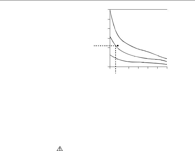
Figure 1-1 provides an example of the relationship between transmitter |
|
housing temperature rise and extension length. |
1-3
Rosemount 644
Figure 1-1. 644 head mount Transmitter Connection Head Temperature Rise vs. Extension Length
Reference Manual
00809-0400-4728, Rev AA
June 2011
Above |
60 (108) |
|
|
|
|
|
|
|
|
|
50 (90) |
|
|
|
|
|
|
|
|
|
|
TemperatureRise, Ambient°C (°F) |
|
|
|
|
|
|
|
|
|
|
22 20 (36) |
|
|
|
|
|
|
|
|
|
|
|
40 (72) |
|
|
|
|
|
|
|
|
|
|
|
815 °C (1500 °F) Oven Temperature |
|
|||||||
|
30 (54) |
|
|
|
|
|
|
|
|
|
|
|
|
|
|
|
|
|
|
|
|
Housing |
|
|
|
540 °C (1000 °F) |
|
|
|
|
|
|
10 (18) |
|
|
Oven Temperature |
|
|
|
|
|||
|
|
|
|
|
|
|
||||
|
|
|
|
|
|
|
|
|
|
|
|
|
|
|
|
|
|||||
|
0 |
|
250 °C (482 °F) Oven Temperature |
|
||||||
|
|
|
|
|
|
|
|
|
|
|
|
3 |
4 |
5 |
6 |
7 |
8 |
|
9 |
||
3.6Extension Length (in.)
Example
|
The transmitter specification limit is 85 °C. If the ambient temperature is 55 °C |
|
|
and the process temperature to be measured is 800 °C, the maximum |
|
|
permissible connection head temperature rise is the transmitter specification |
|
|
limit minus the ambient temperature (moves 85 to 55 °C), or 30 °C. |
|
|
In this case, an extension of 100 mm meets this requirement, but 125 mm |
|
|
provides a margin of 8 °C, thereby reducing any temperature effects in the |
|
|
transmitter. |
|
RETURN OF MATERIALS |
To expedite the return process in North America, call the Emerson Process |
|
|
Management National Response Center toll-free at 800-654-7768. This |
|
|
center, available 24 hours a day, will assist you with any needed information |
|
|
or materials. |
|
|
The center will ask for the following information: |
|
|
• |
Product model |
|
• |
Serial numbers |
|
• The last process material to which the product was exposed |
|
|
The center will provide |
|
|
• A Return Material Authorization (RMA) number |
|
|
• Instructions and procedures that are necessary to return goods that |
|
|
|
were exposed to hazardous substances |
|
For other locations, please contact a Emerson Process Management sales |
|
|
representative. |
|
|
|
|
|
NOTE |
|
|
If a hazardous substance is identified, a Material Safety Data Sheet (MSDS), |
|
|
required by law to be available to people exposed to specific hazardous |
|
|
substances, must be included with the returned materials. |
|
PRODUCT |
|
|
Recycling of equipment and packaging should be taken into consideration |
||
RECYCLING/DISPOSAL |
and disposed of in accordance with local and national legislation/regulations. |
|
1-4
Reference Manual
00809-0400-4728, Rev AA
June 2011
Rosemount 644
Section 2 |
Installation |
SAFETY MESSAGES
Warnings
Safety Messages . . . . . . . . . . . . . . . . . . . . . . . . . . . . . . . . . page 2-1 Mounting . . . . . . . . . . . . . . . . . . . . . . . . . . . . . . . . . . . . . . . page 2-3 Installation . . . . . . . . . . . . . . . . . . . . . . . . . . . . . . . . . . . . . . page 2-4 Wiring . . . . . . . . . . . . . . . . . . . . . . . . . . . . . . . . . . . . . . . . . . page 2-7 Power Supply . . . . . . . . . . . . . . . . . . . . . . . . . . . . . . . . . . . page 2-11
Instructions and procedures in this section may require special precautions to ensure the safety of the personnel performing the operations. Information that potentially raises safety issues is indicated by a warning symbol ( ). Please refer to the following safety messages before performing an operation preceded by this symbol.
Failure to follow these installation guidelines could result in death or serious injury.
•Make sure only qualified personnel perform the installation.
Explosions could result in death or serious injury.
•Do not remove the connection head cover in explosive atmospheres when the circuit is live.
•Before connecting a Field Communicator in an explosive atmosphere, make sure the instruments in the loop are installed in accordance with intrinsically safe or non-incendive field wiring practices.
•Verify that the operating atmosphere of the transmitter is consistent with the appropriate hazardous locations certifications.
•All connection head covers must be fully engaged to meet explosion-proof requirements.
Process leaks could result in death or serious injury.
•Do not remove the thermowell while in operation.
•Install and tighten thermowells and sensors before applying pressure.
Electrical shock could cause death or serious injury.
•Use extreme caution when making contact with the leads and terminals.
www.rosemount.com
Rosemount 644
Reference Manual
00809-0400-4728, Rev AA
June 2011
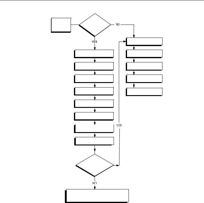
Figure 2-1. Installation Flowchart
START
HERE
Bench
Calibration?
BASIC SETUP
Set Sensor Type
Set Number of Wires
Set Units
Set Range Values
Set Damping
VERIFY
Simulate Sensor Input
FIELD INSTALL
Set Failure Mode
Switch
Mount Transmitter
Wire Transmitter
Power Transmitter
FINISHED
Does not apply to the 644 with FOUNDATION fieldbus
Within
Specifications?
Refer to Section 3: Configuration
2-2
Reference Manual
00809-0400-4728, Rev AA
June 2011
Rosemount 644
MOUNTING |
Mount the transmitter at a high point in the conduit run to prevent moisture |
|
from draining into the transmitter housing. |
The 644 head mount installs:
•In a connection head or universal head mounted directly on a sensor assembly
•Apart from a sensor assembly using a universal head
•To a DIN rail using an optional mounting clip.
The 644 rail mount attaches directly to a wall or to a DIN rail.
Mounting a 644H to a DIN Rail
To attach a head mount transmitter to a DIN rail, assemble the appropriate rail mounting kit (part number 00644-5301-0010) to the transmitter as shown in Figure 2-2.
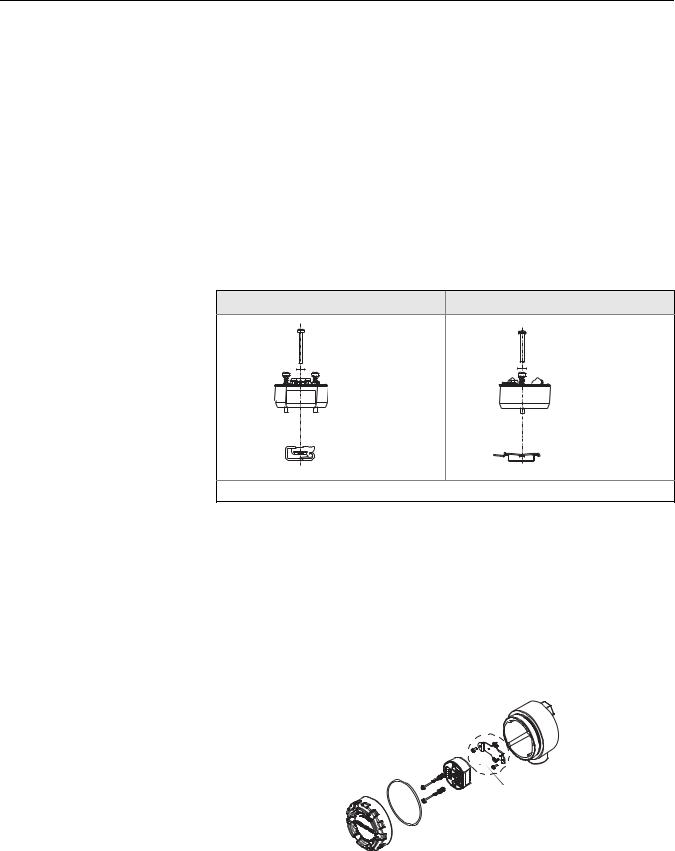
Figure 2-2. Assembling Rail Clip Hardware to a 644H
G-Rail (asymmetric) |
Top Hat Rail (symmetric) |
Mounting |
Mounting |
Hardware |
Hardware |
Transmitter |
Transmitter |
Rail Clip |
Rail Clip |
Note: Kit includes Mounting Hardware and both types of Rail Kits.
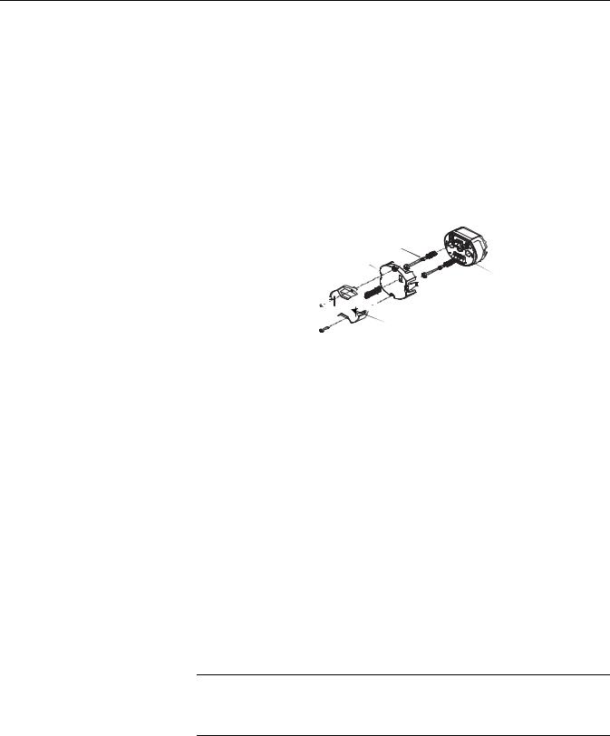
Figure 2-3. Assembling 644H for Use in an Existing L1 Connection Head
Retrofitting a 644H for Use in an Existing Threaded Sensor Connection Head
To mount a 644H in an existing threaded sensor connection head (former option code L1), order the 644H retrofit kit (part number 00644-5321-0010). The retrofit kit includes a new mounting bracket and all associated hardware necessary to facilitate the installation of the 644H in the existing head. See Figure 2-3.
Existing Threaded Sensor Connection Head
(Former option code L1)

Kit includes replacement bracket and screws.
2-3
Rosemount 644
Reference Manual
00809-0400-4728, Rev AA
June 2011
INSTALLATION
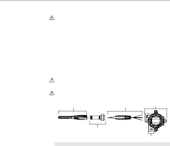
Typical European
Installation
Head Mount Transmitter with DIN Plate Style Sensor
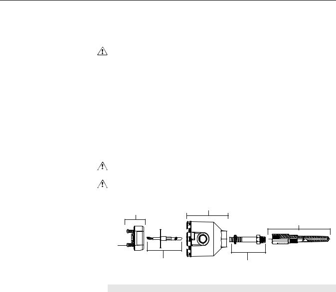
1.Attach the thermowell to the pipe or process container wall. Install and tighten the thermowell before applying process pressure.
2.Assemble the transmitter to the sensor. Push the transmitter mounting screws through the sensor mounting plate and insert the snap rings (optional) into the transmitter mounting screw groove.
3.Wire the sensor to the transmitter (see Figure 2-7 on page 2-8).
4.Insert the transmitter-sensor assembly into the connection head. Thread the transmitter mounting screw into the connection head mounting holes. Assemble the extension to the connection head. Insert the assembly into the thermowell.
5.Attach a cable gland into the shielded cable.
6.Insert the shielded cable leads into the connection head through the cable entry. Connect and tighten the cable gland.
7.Connect the shielded power cable leads to the transmitter power terminals. Avoid contact with sensor leads and sensor connections.
8.Install and tighten the connection head cover. Enclosure covers must be fully engaged to meet explosion-proof requirements.
A
D
E
A = 644H Transmitter
B = Connection Head
C = Thermowell
B
C
F
D = Transmitter Mounting Screws
E = Integral Mount Sensor with Flying Leads F = Extension
2-4
Reference Manual
00809-0400-4728, Rev AA
June 2011
Rosemount 644
Typical North American
Installation
Head Mount Transmitter with Threaded Sensor
1.Attach the thermowell to the pipe or process container wall. Install and tighten thermowells before applying process pressure.
2.Attach necessary extension nipples and adapters to the thermowell. Seal the nipple and adapter threads with silicone tape.
3.Screw the sensor into the thermowell. Install drain seals if required for severe environments or to satisfy code requirements.
4.Pull the sensor wiring leads through the universal head and transmitter. Mount the transmitter in the universal head by threading the transmitter mounting screws into the universal head mounting holes.
5.Mount the transmitter-sensor assembly into the thermowell. Seal adapter threads with silicone tape.
6.Install conduit for field wiring to the conduit entry of the universal head. Seal conduit threads with silicone tape.
7.Pull the field wiring leads through the conduit into the universal head. Attach the sensor and power leads to the transmitter. Avoid contact with other terminals.
8.Install and tighten the universal head cover. Enclosure covers must be fully engaged to meet explosion-proof requirements.
A B D
|
C |
|
E |
A = Threaded Thermowell |
D = Universal Head |
B = Threaded Style Sensor |
E = Conduit Entry |
C = Standard Extension |
|
2-5
Rosemount 644
Reference Manual
00809-0400-4728, Rev AA
June 2011
LCD Display Installation
The LCD display provides local indication of the transmitter output and abbreviated diagnostic messages governing transmitter operation. Transmitters ordered with the LCD display are shipped with the meter installed. After-market installation of the meter can be performed if the transmitter has a meter connector (transmitter revision 5.5.2 or later). After-market installation requires the meter kit (part number 00644-4430-0001), which includes:
•LCD display assembly (includes LCD display, meter spacer, and 2 screws)
•Meter cover with O-ring in place
Figure 2-4. Installing the LCD
Display
Captive Mounting Screws and Springs
Meter Spacer
644H


 10 pin Connector
 LCD Display
Use the following procedure to install the meter.
1.If the transmitter is installed in a loop, secure the loop and disconnect the power. If the transmitter is installed in an enclosure, remove the cover from the enclosure.
2.Decide meter orientation (the meter can be rotated in 90° increments). To change meter orientation, remove the screws located above and below the display screen. Lift the meter off the meter spacer. Remove the 8-pin plug and re-insert it in the location that will result in the desired viewing orientation.
3.Reattach the meter to the meter spacer using the screws. If the meter was rotated 90° from its original position, it will be necessary to remove the screws from their original holes and re-insert them in the adjacent screw’s holes.
4.Line up the 10-pin connector with the 10-pin socket and push the meter into the transmitter until it snaps into place.
5.Attach the meter cover; tighten at least one-third turn after the O-ring contacts the transmitter housing. The cover must be fully engaged to meet explosion-proof requirements.
6.Use a Field Communicator, AMS software, or a FOUNDATION fieldbus Communication tool to configure the meter to the desired display.
NOTE
Observe the following LCD display temperature limits:
Operating: –4 to 185 °F (–20 to 85 °C)
Storage: –50 to 185 °F (–45 to 85 °C)
2-6
Reference Manual
00809-0400-4728, Rev AA
June 2011
Rosemount 644
WIRING |
All power to the transmitter is supplied over the signal wiring. Use ordinary |
|
copper wire of sufficient size to ensure that the voltage across the transmitter |
|
power terminals does not drop below 9 Vdc. |
If the sensor is installed in a high-voltage environment and a fault condition or installation error occurs, the sensor leads and transmitter terminals could carry lethal voltages. Use extreme caution when making contact with the leads and terminals.
NOTE
Do not apply high voltage (e.g., ac line voltage) to the transmitter terminals. Abnormally high voltage can damage the unit. (Sensor and transmitter power terminals are rated to 42.4 Vdc. A constant 42.4 volts across the sensor terminals may damage the unit.)
The transmitters will accept inputs from a variety of RTD and thermocouple types. Refer to Figure 2-5 on page 2-7 when making sensor connections. Refer to Figure 2-6 on page 2-8 for FOUNDATION fieldbus installations.
Use the following steps to wire the power and sensor to the transmitter:
1.Remove the terminal block cover (if applicable).
2.Connect the positive power lead to the “+” terminal. Connect the negative power lead to the “–” terminal (see Figure 2-7).
3.Tighten the terminal screws. When tightening the sensor and power wires, the max torque is 6-in.-lbs (0.7 N-m).
4.Reattach and tighten the cover (if applicable).
5.Apply power (see “Power Supply”).
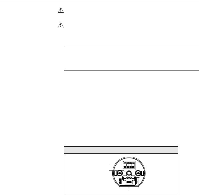
Figure 2-5. Transmitter Power,
Communication, and Sensor
Terminals
644H
Sensor |
|
|
|
|
Terminals |
|
|
|
|
Communication |
1 |
2 |
3 |
4 |
|
|
|
|
|
Terminals |
|
|
|
|
Power Terminals |
2-7
Rosemount 644
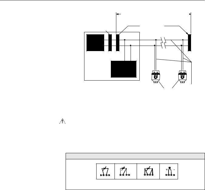
Figure 2-6. Connecting a
FOUNDATION fieldbus Host
System to a Transmitter Loop
Integrated Power
Conditioner and Filter
Power
Supply
(The power supply, filter, first terminator, and configuration tool are typically located in the control room.)
Reference Manual
00809-0400-4728, Rev AA
June 2011
6234 ft (1900 m) max (depending upon cable characteristics)
Terminators
(Trunk)
(Spur)
FOUNDATION
fieldbus
Configuration
Tool
(Spur) |
|
|
Power/ |
Devices 1 |
Signal |
through 16 |
Wiring |
Sensor Connections
The 644 is compatible with a number of RTD and thermocouple sensor types. Figure 2-7 shows the correct input connections to the sensor terminals on the transmitter. To ensure a proper sensor connection, anchor the sensor lead wires into the appropriate compression terminals and tighten the screws.
Figure 2-7. Sensor Wiring
Diagrams
644 Sensor Connections Diagram
1 2 3 4 |
1 2 3 4 |
1 2 3 4 |
1 2 3 4 |
2-wire |
3-wire RTD* |
4-wire RTD |
T/C |
RTD and |
and |
and |
and mV |
*Emerson Process Management provides 4-wire sensors for all single element RTDs. Use these
RTDs in 3-wire configurations by leaving the unneeded leads disconnected and insulated with electrical tape.
Thermocouple or Millivolt Inputs
The thermocouple can be connected directly to the transmitter. Use appropriate thermocouple extension wire if mounting the transmitter remotely from the sensor. Make millivolt inputs connections with copper wire. Use shielding for long runs of wire.
2-8

Reference Manual
00809-0400-4728, Rev AA
June 2011
Rosemount 644
RTD or Ohm Inputs
The transmitters will accept a variety of RTD configurations, including 2-wire, 3-wire, or 4-wire. If the transmitter is mounted remotely from a 3-wire or 4-wire RTD, it will operate within specifications, without recalibration, for lead wire resistances of up to 60 ohms per lead (equivalent to 6,000 feet of 20 AWG wire). In this case, the leads between the RTD and transmitter should be shielded. If using only two leads, both RTD leads are in series with the sensor element, so significant errors can occur if the lead lengths exceed three feet of 20 AWG wire (approximately 0.05 °C/ft). For longer runs, attach a third or fourth lead as described above.
Sensor Lead Wire Resistance Effect– RTD Input
When using a 4-wire RTD, the effect of lead resistance is eliminated and has no impact on accuracy. However, a 3-wire sensor will not fully cancel lead resistance error because it cannot compensate for imbalances in resistance between the lead wires. Using the same type of wire on all three lead wires will make a 3-wire RTD installation as accurate as possible. A 2-wire sensor will produce the largest error because it directly adds the lead wire resistance to the sensor resistance. For 2- and 3-wire RTDs, an additional lead wire resistance error is induced with ambient temperature variations. The table and the examples shown below help quantify these errors.
Table 2-1. Examples of
Approximate Basic Error |
|
Sensor Input |
Approximate Basic Error |
|
|
|
4-wire RTD |
None (independent of lead wire resistance) |
|
|
|
3-wire RTD |
± 1.0 in reading per ohm of unbalanced lead wire resistance |
|
|
|
|
(Unbalanced lead wire resistance = maximum imbalance between |
|
|
|
|
any two leads.) |
|
|
|
2-wire RTD |
1.0 in reading per ohm of lead wire resistance |
|
|
Examples of Approximate Lead Wire Resistance Effect Calculations |
|||
|
Given: |
|
|
|
|
|
Total cable length: |
150 m |
|
|
|
Imbalance of the lead wires at 20 °C: |
1.5 |
|
|
|
Resistance/length (18 AWG Cu): |
0.025 /m °C |
|
|
|
Temperature coefficient of Cu ( Cu): |
0.039 / °C |
|
|
|
Temperature coefficient of Pt( Pt): |
0.00385 / °C |
|
|
|
Change in Ambient Temperature ( Tamb): |
25 °C |
|
|
|
RTD Resistance at 0 °C (Ro): |
100 (for Pt 100 RTD) |
|
|
• Pt100 4-wire RTD: No lead wire resistance effect. |
|||
|
• |
Pt100 3-wire RTD: |
|
|
|
|
Basic Error = |
Imbalance------------------------------of------Lead----------------Wires------------- |
|
|
|
|
Pt Ro |
|
Cu Tamb Imbalance of Lead Wires Error due to amb. temp. variation = ------------------------------------------------------------------------------------------------------------------------
Pt Ro
2-9

Rosemount 644
Reference Manual
00809-0400-4728, Rev AA
June 2011
Lead wire imbalance seen by the transmitter = 0.5
Basic error = |
0.5 |
= 1.3 C |
---0.00385------------------------------/--------------C----------------100------------------ |
Error due to amb. temp. var. of 25 °C
0.0039 / C 25 C 0.5
=------------------------------------------------------------------------------------------------------- = 0.1266 C
0.00385 / C 100
•Pt100 2-wire RTD:
Lead Wire Resistance
Basic Error = ----------------------------------------------------------
Pt Ro
Cu Tamb Lead Wire Resistance Error due to amb. temp. variation = ----------------------------------------------------------------------------------------------------------------
Pt Ro
Lead wire resistance seen by the transmitter = 150 m × 2 wires × 0.025 /m = 7.5
Basic error = |
7.5 |
|
= 19.5 C |
---0.00385-------------------------------/-------------C----------------100------------- |
----- |
Error due to amb. temp. var. of 25 °C
0.0039 / C 25 C 7.5
=------------------------------------------------------------------------------------------------------- = 1.9 C
0.00385 / C 100
2-10
Reference Manual
00809-0400-4728, Rev AA
June 2011
Rosemount 644
POWER SUPPLY
FOUNDATION fieldbus Installation
Ground the Transmitter
Powered over FOUNDATION fieldbus with standard fieldbus power supplies. The transmitter operates between 9.0 and 32.0 Vdc, 11 mA maximum. Transmitter power terminals are rated to 42.4 Vdc.
The power terminals on the 644 with FOUNDATION fieldbus are polarity insensitive.
The transmitter will operate with the current signal loop either floating or grounded. However, the extra noise in floating systems affects many types of readout devices. If the signal appears noisy or erratic, grounding the current signal loop at a single point may solve the problem. The best place to ground the loop is at the negative terminal of the power supply. Do not ground the current signal loop at more than one point.
The transmitter is electrically isolated to 500 Vdc/ac rms (707 Vdc), so the input circuit may also be grounded at any single point. When using a grounded thermocouple, the grounded junction serves as this point.
Neither side of the loop should be grounded on FOUNDATION fieldbus devices. Only the shield wire should be grounded.
NOTE
Do not ground the signal wire at both ends.
Ungrounded Thermocouple, mV, and RTD/Ohm Inputs
Each process installation has different requirements for grounding. Use the grounding options recommended by the facility for the specific sensor type or begin with grounding Option 1 (the most common).
Option 1:
1.Connect signal wiring shield to the sensor wiring shield.
2.Ensure the two shields are tied together and electrically isolated from the transmitter housing.
3.Ground shield at the power supply end only.
4.Ensure that the sensor shield is electrically isolated from the surrounding grounded fixtures.
Sensor Wires
Transmitter
Shield ground point
FOUNDATION Fieldbus segment
Connect shields together, electrically isolated from the transmitter
2-11
Rosemount 644
Reference Manual
00809-0400-4728, Rev AA
June 2011
Option 2:
1.Connect sensor wiring shield to the transmitter housing (only if the housing is grounded).
2.Ensure the sensor shield is electrically isolated from surrounding fixtures that may be grounded.
3.Ground signal wiring shield at the power supply end.
FOUNDATION Fieldbus segment
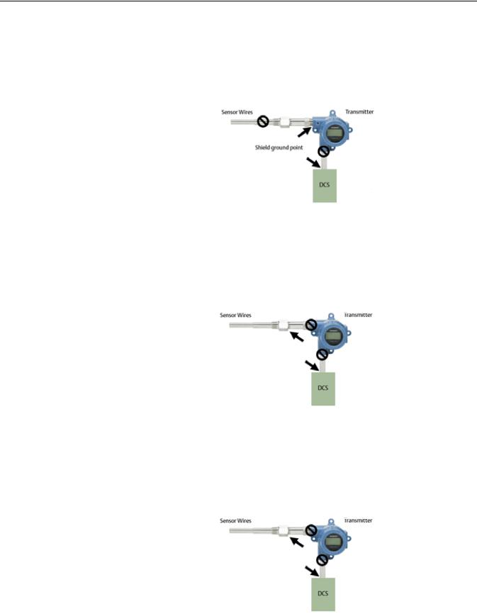
Option 3:
1.Ground sensor wiring shield at the sensor, if possible.
2.Ensure that the sensor wiring and signal wiring shields are electrically isolated from the transmitter housing.
3.Do not connect the signal wiring shield to the sensor wiring shield.
4.Ground signal wiring shield at the power supply end.
|
|
|
|
|
Sensor Wires |
|
|
|
|
|
Transmitter |
|
||
|
|
|
|
|
Shield ground point |
|
|
|
|
FOUNDATION Fieldbus segment
Grounded Thermocouple Inputs
1.Ground sensor wiring shield at the sensor.
2.Ensure that the sensor wiring and signal wiring shields are electrically isolated from the transmitter housing.
3.Do not connect the signal wiring shield to the sensor wiring shield.
4.Ground signal wiring shield at the power supply end.
|
|
|
|
|
Sensor Wires |
|
|
|
|
|
Transmitter |
|
||
|
|
|
|
|
Shield ground point |
|
|
|
|
FOUNDATION Fieldbus segment
2-12

Reference Manual
00809-0400-4728, Rev AA
June 2011
Rosemount 644
Section 3 |
Configuration |
OVERVIEW
SAFETY MESSAGES
Warnings
Overview . . . . . . . . . . . . . . . . . . . . . . . . . . . . . . . . . . . . . . . page 3-1 Safety Messages . . . . . . . . . . . . . . . . . . . . . . . . . . . . . . . . . page 3-1 General Block Information . . . . . . . . . . . . . . . . . . . . . . . . . page 3-2 FOUNDATION fieldbus function blocks . . . . . . . . . . . . . . . . page 3-4 Operation and Maintenance . . . . . . . . . . . . . . . . . . . . . . . . page 3-15
This section provides information on configuring, troubleshooting, operating, and maintaining the Rosemount 644 Temperature transmitter using FOUNDATION fieldbus protocol.
Instructions and procedures in this section may require special precautions to ensure the safety of the personnel performing the operations. Information that potentially raises safety issues is indicated by a warning symbol ( ). Please refer to the following safety messages before performing an operation preceded by this symbol.
Failure to follow these installation guidelines could result in death or serious injury.
•Make sure only qualified personnel perform the installation.
Explosions could result in death or serious injury.
•Do not remove the connection head cover in explosive atmospheres when the circuit is live.
•Before powering a FOUNDATION fieldbus segment in an explosive atmosphere, make sure the instruments in the loop are installed in accordance with intrinsically safe or non-incendive field wiring practices.
•Verify that the operating atmosphere of the transmitter is consistent with the appropriate hazardous locations certifications.
•All connection head covers must be fully engaged to meet explosion-proof requirements.
Process leaks could result in death or serious injury.
•Do not remove the thermowell while in operation.
•Install and tighten thermowells and sensors before applying pressure.
Electrical shock could cause death or serious injury.
•Use extreme caution when making contact with the leads and terminals.
www.rosemount.com

Rosemount 644
Reference Manual
00809-0400-4728, Rev AA
June 2011
GENERAL BLOCK INFORMATION
Device Description
Before configuring the device, ensure the host has the appropriate Device Description file revision for this device. The device descriptor can be found on www.rosemount.com. The initial release of the Rosemount 644 with FOUNDATION fieldbus protocol is device revision 1.
Node Address
The transmitter is shipped at a temporary (248) address. This will enable FOUNDATION fieldbus host systems to automatically recognize the device and move it to a permanent address.
Modes |
The Resource, Transducer, and all function blocks in the device have modes |
|
of operation. These modes govern the operation of the block. Every block |
|
supports both automatic (AUTO) and out of service (OOS) modes. Other |
|
modes may also be supported. |
|
Changing Modes |
|
To change the operating mode, set the MODE_BLK.TARGET to the desired |
|
mode. After a short delay, the parameter MODE_BLOCK.ACTUAL should |
|
reflect the mode change if the block is operating properly. |
|
Permitted Modes |
|
It is possible to prevent unauthorized changes to the operating mode of a |
|
block. To do this, configure MODE_BLOCK.PERMITTED to allow only the |
|
desired operating modes. It is recommended to always select OOS as one of |
|
the permitted modes. |
|
Types of Modes |
|
For the procedures described in this manual, it will be helpful to understand |
|
the following modes: |
|
AUTO |
|
The functions performed by the block will execute. If the block has any |
|
outputs, these will continue to update. This is typically the normal |
|
operating mode. |
|
Out of Service (OOS) |
|
The functions performed by the block will not execute. If the block has any |
|
outputs, these will typically not update and the status of any values passed |
|
to downstream blocks will be “BAD.” To make some changes to the |
|
configuration of the block, change the mode of the block to OOS. When |
|
the changes are complete, change the mode back to AUTO. |
|
MAN |
|
In this mode, variables that are passed out of the block can be manually |
|
set for testing or override purposes. |
|
Other Types of Modes |
|
Other types of modes are Cas, RCas, ROut, IMan, and LO. Some of these |
|
may be supported by different function blocks in the 644. For more |
|
information, see the Function Block manual (document number |
|
00809-0100-4783). |
3-2

Reference Manual
00809-0400-4728, Rev AA
June 2011
Rosemount 644
NOTE
When an upstream block is set to OOS, this will impact the output status of all downstream blocks. The figure below depicts the hierarchy of blocks:
Link Active Scheduler
Block Installation
Resource |
|
|
Transducer |
|
Analog Input |
|
|
Other |
Block |
|
|
Block |
|
(AI Block) |
|
|
Function |
|
|
|
|
|
||||
|
|
|
|
|
|
|
|
Blocks |
|
|
|
|
|
|
|
|
|
The 644 can be designated to act as the backup Link Active Scheduler (LAS) in the event that the designated LAS is disconnected from the segment. As the backup LAS, the 644 will take over the management of communications until the host is restored.
The host system may provide a configuration tool specifically designed to designate a particular device as a backup LAS. Otherwise, this can be configured manually as follows:
1.Access the Management Information Base (MIB) for the 644. To activate the LAS capability, write 0x02 to the BOOT_OPERAT_FUNCTIONAL_CLASS object (Index 605). To deactivate, write 0x01.
2.Restart the device.
Rosemount devices are pre-configured with function blocks at the factory, the default permanent configuration for the 644 is listed below. The 644 can have up to ten additional instantiated function blocks.
•2 Analog Input Blocks (tag names AI 1300, AI 1400)
•1 Proportional/Integral/Derivative Block (tag name PID 1500)
The 644 supports the use of Function Block Instantiation. When a device supports block instantiation, the number of blocks and block types can be defined to match specific application needs.The number of blocks that can be instantiated is only limited by the amount of memory within the device and the block types that are supported by the device. Instantiation does not apply to standard device blocks like the Resource, Sensor Transducer, LCD Transducer, and Advanced Diagnostics Blocks.
By reading the parameter “FREE_SPACE” in the Resource block you can determine how many blocks you can instantiate. Each block that you instantiate takes up 4.5% of the “FREE_SPACE.”
Block instantiation is done by the host control system or configuration tool, but not all hosts are required to implement this functionality. Please refer to your specific host or configuration tool manual for more information.
3-3

Rosemount 644
Reference Manual
00809-0400-4728, Rev AA
June 2011
Capabilities
FOUNDATION FIELDBUS
FUNCTION BLOCKS
Virtual Communication Relationship (VCRs)
There are a total of 12 VCRs. One is permanent and 11 are fully configurable by the host system. Sixteen link objects are available.
Network Parameter |
Value |
Slot Time |
8 |
Maximum Response Delay |
2 |
Maximum Inactivity to Claim LAS Delay |
32 |
Minimum Inter DLPDU Delay |
8 |
Time Sync class |
4 (1ms) |
Maximum Scheduling Overhead |
21 |
Per CLPDU PhL Overhead |
4 |
Maximum Inter-channel Signal Skew |
0 |
Required Number of Post-transmission-gab-ext Units |
0 |
Required Number of Preamble-extension Units |
1 |
Block Execution times
Analog Input = 45 ms
PID = 60 ms
For reference information on the Resource, Sensor Transducer, AI, LCD Transducer blocks refer to FOUNDATION fieldbus Block Information on page A-1. Reference information on the PID block can be found in the Function Block manual document number 00809-0100-4783.
Resource Block (index number 1000)
The Resource Function Block (RB) contains diagnostic, hardware, and electronics information. There are no linkable inputs or outputs to the Resource Block.
Sensor Transducer Block (index number 1100)
The Sensor Transducer Function Block (STB) temperature measurement data includes sensor and terminal temperature. The STB also includes information about sensor type, engineering units, linearization, reranging, damping, temperature compensation, and diagnostics.
LCD Transducer Block (index number 1200)
The LCD Transducer Block is used to configure the LCD meter.
Analog Input Block (index number 1300 and 1400)
The Analog Input Function Block (AI) processes the measurements from the sensor and makes them available to other function blocks. The output value from the AI block is in engineering units and contains a status indicating the quality of the measurement. The AI block is widely used for scaling functionality.
PID Block (index number 1500)
The PID Function Block combines all of the necessary logic to perform proportional/integral/derivative (PID) control. The block supports mode control, signal scaling and limiting, feed forward control, override tracking, alarm limit detection, and signal status propagation.
3-4

Reference Manual
00809-0400-4728, Rev AA
June 2011
Rosemount 644
Resource Block
The block supports two forms of the PID equation: Standard and Series. You can choose the appropriate equation using the MATHFORM parameter. The Standard ISA PID equation is the default selection.
FEATURES and FEATURES_SEL
The parameters FEATURES and FEATURE_SEL determine optional behavior of the 644.
FEATURES
The FEATURES parameter is read only and defines which features are supported by the 644. Below is a list of the FEATURES the 644 supports.
UNICODE
All configurable string variables in the 644, except tag names, are octet strings. Either ASCII or Unicode may be used. If the configuration device is generating Unicode octet strings, you must set the Unicode option bit.
REPORTS
The 644 supports alert reports. The Reports option bit must be set in the features bit string to use this feature. If it is not set, the host must poll for alerts.
SOFT W LOCK
Inputs to the security and write lock functions include the software write lock bits of the FEATURE_SEL parameter, the WRITE_LOCK parameter, and the DEFINE_WRITE_LOCK parameter.
The WRITE_LOCK parameter prevents modification of parameters within the device except to clear the WRITE_LOCK parameter. During this time, the block will function normally updating inputs and outputs and executing algorithms. When the WRITE_LOCK condition is cleared, a WRITE_ALM alert is generated with a priority that corresponds to the WRITE_PRI parameter.
The FEATURE_SEL parameter enables the user to select the software write lock or no write lock capability. In order to enable the software write lock, the SOFT_W_LOCK bit must be set in the FEATURE_SEL parameter. Once this bit is set, the WRITE_LOCK parameter may be set to “Locked” or “Unlocked.” Once the WRITE_LOCK parameter is set to “Locked” by the software, all user requested writes as determined by the DEFINE_WRITE_LOCK parameter shall be rejected.
The DEFINE_WRITE_LOCK parameter allows the user to configure whether the write lock function will control writing to all blocks, or only to the resource and transducer blocks. Internally updated data such as process variables and diagnostics will not be restricted.
N/A = No blocks are blocked
Physical = Locks resource and transducer block Everything = Locks every block.
3-5

Rosemount 644
Reference Manual
00809-0400-4728, Rev AA
June 2011
The following table displays all possible configurations of the WRITE_LOCK parameter.
FEATURE_SEL |
|
|
WRITE_LOCK |
|
Write access |
SW_SEL bit |
WRITE_LOCK |
Read/Write |
DEFINE_WRITE_LOCK |
to blocks |
|
0 (off) |
1 |
(unlocked) |
Read only |
NA |
All |
1 (on) |
1 |
(unlocked) |
Read/Write |
NA |
All |
1 (on) |
2 |
(locked) |
Read/Write |
Physical |
Function |
|
|
|
|
|
Blocks only |
1 (on) |
2 |
(locked) |
Read/Write |
Everything |
None |
FEATURES_SEL
FEATURES_SEL is used to turn on any of the supported features. The default setting of the 644 does not select any of these features. Choose one of the supported features if any.
MAX_NOTIFY
The MAX_NOTIFY parameter value is the maximum number of alert reports that the resource can have sent without getting a confirmation, corresponding to the amount of buffer space available for alert messages. The number can be set lower, to control alert flooding, by adjusting the LIM_NOTIFY parameter value. If LIM_NOTIFY is set to zero, then no alerts are reported.
PlantWeb™ Alerts
The alerts and recommended actions should be used in conjunction with “Operation and Maintenance” on page 3-15.
The Resource Block will act as a coordinator for PlantWeb alerts. There will be three alarm parameters (FAILED_ALARM, MAINT_ALARM, and ADVISE_ALARM) which will contain information regarding some of the device errors which are detected by the transmitter software. There will be a RECOMMENDED_ACTION parameter which will be used to display the recommended action text for the highest priority alarm and a HEALTH_INDEX parameters (0 - 100) indicating the overall health of the transmitter. FAILED_ALARM will have the highest priority followed by MAINT_ALARM and ADVISE_ALARM will be the lowest priority.
FAILED_ALARMS
A failure alarm indicates a failure within a device that will make the device or some part of the device non-operational. This implies that the device is in need of repair and must be fixed immediately. There are five parameters associated with FAILED_ALARMS specifically, they are described below.
FAILED_ENABLED
This parameter contains a list of failures in the device which makes the device non-operational that will cause an alert to be sent. Below is a list of the failures with the highest priority first.
1.Electronics
2.NV Memory
3.HW / SW Incompatible
4.Primary Value
5.Secondary Value
3-6

Reference Manual
00809-0400-4728, Rev AA
June 2011
Rosemount 644
FAILED_MASK
This parameter will mask any of the failed conditions listed in FAILED_ENABLED. A bit on means that the condition is masked out from alarming and will not be reported.
FAILED_PRI
Designates the alerting priority of the FAILED_ALM, see “Alarm Priority” on page 3-13. The default is 0 and the recommended value are between 8 and 15.
FAILED_ACTIVE
This parameter displays which of the alarms is active. Only the alarm with the highest priority will be displayed. This priority is not the same as the FAILED_PRI parameter described above. This priority is hard coded within the device and is not user configurable.
FAILED_ALM
Alarm indicating a failure within a device which makes the device non-operational.
MAINT_ALARMS
A maintenance alarm indicates the device or some part of the device needs maintenance soon. If the condition is ignored, the device will eventually fail. There are five parameters associated with MAINT_ALARMS, they are described below.
MAINT_ENABLED
The MAINT_ENABLED parameter contains a list of conditions indicating the device or some part of the device needs maintenance soon.
Below is a list of the conditions with the highest priority first.
1.Primary Value Degraded
2.Secondary Value Degraded
3.Diagnostic
4.Configuration Error
5.Calibration Error
MAINT_MASK
The MAINT_MASK parameter will mask any of the failed conditions listed in MAINT_ENABLED. A bit on means that the condition is masked out from alarming and will not be reported.
MAINT_PRI
MAINT_PRI designates the alarming priority of the MAINT_ALM, “Process Alarms” on page 3-12. The default is 0 and the recommended values is 3 to 7.
MAINT_ACTIVE
The MAINT_ACTIVE parameter displays which of the alarms is active. Only the condition with the highest priority will be displayed. This priority is not the same as the MAINT_PRI parameter described above. This priority is hard coded within the device and is not user configurable.
MAINT_ALM
An alarm indicating the device needs maintenance soon. If the condition is ignored, the device will eventually fail.
3-7

Rosemount 644
Reference Manual
00809-0400-4728, Rev AA
June 2011
Advisory Alarms
An advisory alarm indicates informative conditions that do not have a direct impact on the device's primary functions. There are five parameters associated with ADVISE_ALARMS. They are described below.
ADVISE_ENABLED
The ADVISE_ENABLED parameter contains a list of informative conditions that do not have a direct impact on the device's primary functions. Below is a list of the advisories with the highest priority first.
1.NV Writes Deferred
2.SPM Process Anomaly detected
ADVISE_MASK
The ADVISE_MASK parameter will mask any of the failed conditions listed in ADVISE_ENABLED. A bit on means the condition is masked out from alarming and will not be reported.
ADVISE_PRI
ADVISE_PRI designates the alarming priority of the ADVISE_ALM, see “Process Alarms” on page 3-12. The default is 0 and the recommended values are 1 or 2.
ADVISE_ACTIVE
The ADVISE_ACTIVE parameter displays which of the advisories is active. Only the advisory with the highest priority will be displayed. This priority is not the same as the ADVISE_PRI parameter described above. This priority is hard coded within the device and is not user configurable.
ADVISE_ALM
ADVISE_ALM is an alarm indicating advisory alarms. These conditions do not have a direct impact on the process or device integrity.
Recommended Actions for PlantWeb Alerts
RECOMMENDED_ACTION
The RECOMMENDED_ACTION parameter displays a text string that will give a recommended course of action to take based on which type and which specific event of the PlantWeb alerts are active.
3-8
Loading...