


Instruction Manual
Form 5447
March 2009
Types 627W and 627WH
Types 627W and 627WH Direct-Operated
Pressure Reducing Liquid Regulators
!Warning
Fisher® regulators must be installed, operated, and maintained in accordance with federal, state, and local codes, rules and regulations, and manufacturer’s instructions.
Installation, operation, and maintenance procedures performed by unqualified personnel may result in improper adjustment and unsafe operation. Either condition may result in equipment damage or personal
injury. Use qualified personnel when installing, operating, and maintaining the Types 627W and 627WH regulators.
Introduction
Scope of the Manual
This Instruction Manual provides installation, startup, adjustment, maintenance, and parts ordering information for the Types 627W and 627WH pressure reducing regulators for liquid service. Only personnel qualified through training or experience should install, operate, and maintain these regulators. If there are any questions concerning these instructions, contact your local Sales Office before proceeding.
Description
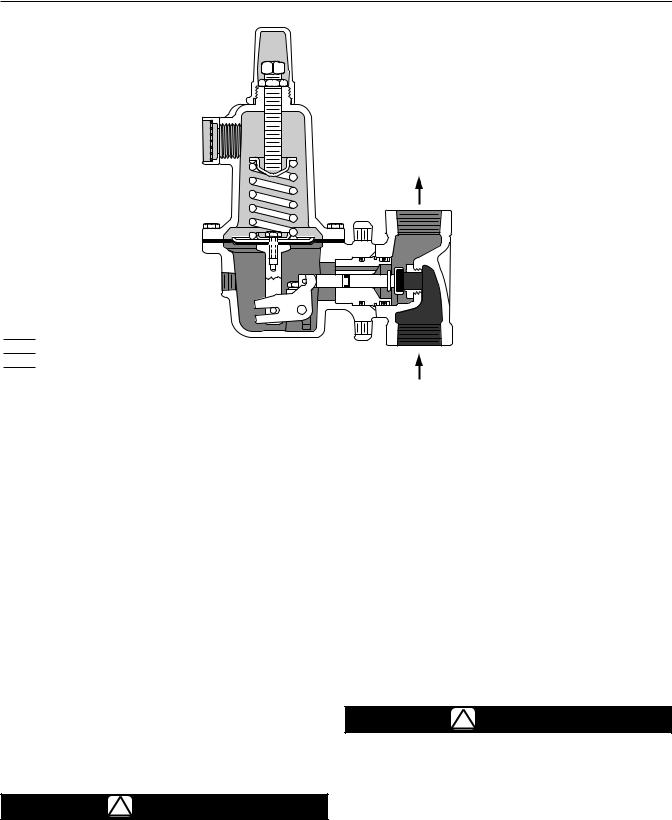
The Types 627W and 627WH (Figure 1) are directoperated pressure reducing regulators for liquid service. On the internal registration version, downstream pressure is registered internally through the body to the underside of the diaphragm.
Types 627W and 627WH direct-operated regulators are also available in a downstream control line version for external pressure registration. The control line version has a blocked throat with an O-ring stem
W4793
Figure 1. Types 627W and 627WH
Pressure Reducing Liquid Regulator
seal and a 1/4 NPT control line connection in the diaphragm case. The stem seal separates the body outlet pressure from the diaphragm case.
Specifications
Refer to Specifications lists for Types 627W and 627WH constructions on page 2. Specifications for a given regulator as it originally comes from the factory are stamped on the spring case nameplate.
D102504X012
www.emersonprocess.com/regulators

Types 627W and 627WH
Specifications
Available Construction
Type 627W: Direct-operated pressure reducing liquid regulator (Figure 2)
Type 627WH: Type 627W with a diaphragm limiter to deliver a higher outlet pressure (Figure 2)
Control Line Option: Type 627W or 627WH with a stem seal between the body outlet pressure
and diaphragm case. Pressure is measured under the diaphragm through the 1/4 NPT
downstream control line connection (Figure 2)
Body Sizes and End Connection Styles
NPT: NPS 3/4, 1, or 2
CL150, CL300, CL600 RF Flanged:
NPS 1 or 2 (DN 25 or 50)
PN 16/25/40: NPS 1 or 2 (DN 25 or 50)
Maximum Spring and Diaphragm Casing Pressure(1)
See Table 1
Body Pressure Shell Rating(1)
NPT (Steel): 2000 psig (138 bar)
NPT (Ductile Iron): 1000 psig (68,9 bar) CL600 RF Flanged (Steel): 1500 psig (103 bar)
Maximum Operating Inlet and Outlet Pressure Ranges(1)
See Table 2 for pressures by orifice and spring range
Outlet Pressure Ranges
Type 627W: 10 to 150 psig (0,69 to 10,3 bar) Type 627WH: 140 to 500 psig (9,7 to 34,5 bar) See Table 2 for pressures by orifice and spring range
Orifice Sizes
Standard: 1/4 or 1/2-inch (6,4 or 13 mm) Optional: 3/32,1/8, 3/16, or 3/8-inch (2,4; 3,2; 4,8; or 9,5 mm)
See Table 8
Temperature Capabilities
See Table 4
Pressure Registration
Standard: Internal
Optional: External through 1/4 NPT control line connection in the diaphragm case
Spring Case Vent Connection
3/4 NPT with removable screened vent assembly
Elastomer Temperature Ranges(1)
See Table 4
Control Line Connection
1/4 NPT downstream control line connection
Wide-Open Cv and IEC Sizing Coefficients
See Table 5
Approximate Weight
10 pounds (5 kg)
Option
Outlet Pressure Gauge (Brass):
0 to 30 psi (0 to 2,1 bar)
0 to 60 psi (0 to 4,1 bar)
0 to 160 psi (0 to 11,0 bar)
0 to 300 psi (0 to 20,7 bar)
0 to 600 psi (0 to 41,4 bar)
1. The pressure/temperature limits in this Instruction Manual or any applicable standard limitation should not be exceeded.
Table 1. Maximum Spring and Diaphragm Casing Pressure(1)
MAXIMUM PRESSURE DESCRIPTION |
DIAPHRAGM CASING material |
TYPE 627W |
TYPE 627WH |
|||
Psig |
bar |
Psig |
bar |
|||
|
|
|||||
Maximum pressure to spring and diaphragm casings to prevent |
Ductile iron |
250 |
17,2 |
- - - - |
- - - - |
|
leak to atmosphere (internal parts damage may occur) |
Steel or Stainless steel |
250 |
17,2 |
800 |
55,2 |
|
|
||||||
|
|
|
|
|
|
|
Maximum pressure to spring and diaphragm casings to prevent |
Ductile iron |
465 |
32,1 |
- - - - |
- - - - |
|
burst of casings during abnormal operation (leak to atmosphere |
|
|
|
|
|
|
Steel or Stainless steel |
1500 |
103 |
1500 |
103 |
||
and internal parts damage may occur) |
||||||
|
|
|
|
|
|
|
Maximum diaphragm casing overpressure (above setpoint) to |
All materials |
60 |
4,1 |
120 |
8,3 |
|
prevent damage to internal parts |
||||||
|
|
|
|
|
||
1. If the spring case is pressurized, a metal adjusting screw cap is required. Contact your local Sales Office for details.
2

Types 627W and 627WH
|
ADJUSTING |
SCREENED |
SCREW CAP |
|
|
VENT |
|
ASSEMBLY |
ADJUSTING |
|
SCREW |
|
SPRING CASE |
|
CONTROL SPRING |
INTERNAL
REGISTRATION
DISK ASSEMBLY
DIAPHRAGM
PUSHER
POST
W6306-1
DETAIL OF TYPE 627W WITH INTERNAL
DOWNSTREAM PRESSURE REGISTRATION
|
|
|
|
|
ADJUSTING |
|
|
|
|
|
SCREW CAP |
|
|
|
|
|
ADJUSTING |
|
|
|
|
|
SCREW |
SCREENED |
|
|
|||
VENT |
|
SPRING CASE |
|||
ASSEMBLY |
|
||||
|
|
|
|
|
CONTROL SPRING |
|
|
|
|
|
DIAPHRAGM |
|
|
|
|
|
head |
DIAPHRAGM |
|
INTERNAL |
|||
|
REGISTRATION |
||||
LIMITER |
|
||||
|
DISK ASSEMBLY |
||||
O-RING |
|
|
|||
|
|
||||
DIAPHRAGM |
|
|
|||
LIMITER |
|
|
|
|
|
|
|
|
|||
DIAPHRAGM
PUSHER
POST
W6305-1
DETAIL OF TYPE 627WH WITH INTERNAL
DOWNSTREAM PRESSURE REGISTRATION
1/4 NPT
CONTROL LINE CONNECTION
W6483-2
DETAIL OF TYPE 627W WITH EXTERNAL
DOWNSTREAM PRESSURE REGISTRATION
1/4 NPT
CONTROL LINE CONNECTION
W5482-1
DETAIL OF TYPE 627WH WITH EXTERNAL DOWNSTREAM PRESSURE REGISTRATION AND CONNECTION FOR OUTLET PRESSURE GAUGE
Figure 2. Types 627W and 627WH Construction Details
3
Types 627W and 627WH

 inlet pressure

 OUTlet pressure

 ATMOSPHERIC pressure
M1037
Figure 3. Type 627W Operational Schematic (Also Typical of Type 627WH)
Principle of Operation
The Type 627W or 627WH (refer to Figure 2) is a direct-operated regulator. On the internal registration version, downstream pressure is registered internally through the body to the under side of the diaphragm. When the downstream pressure is at or above the set pressure, the disk is held against the seat, and there is no flow through the regulator. When demand
increases, downstream pressure drops slightly allowing the spring to extend, moving the stem down and the disk away from the seat. This allows flow through the body to the downstream system.
Types 627W and 627WH direct-operated regulators are also available in a downstream control line version. This version has a stem seal between the body outlet pressure and diaphragm case. Pressure is registered under the diaphragm through the 1/4 NPT downstream control line connection (Figure 2).
Installation
!Warning
Personal injury, equipment damage, or leakage due to escaping liquid or bursting of pressure-containing parts may result if this regulator is
overpressured or installed where service
connection could exceed the limits given in Tables 1, 2, and 4 or where conditions exceed any ratings of the adjacent piping or piping connections.
To avoid such injury or damage, provide pressure-relieving or pressure-limiting devices to prevent service conditions from exceeding those limits.
Additionally, the control line could be broken off the regulator by physical damage, causing personal injury and property damage due to escaping liquid. To avoid such injury and damage, install the regulators and control line where they are protected from physical damage.
caution
Liquid pressure control systems should be designed using engineering practices to eliminate quick control starting or stopping of the flow stream, which can produce water hammer.
Regulator operation within ratings does not preclude the possibility of damage from debris in the lines or from external sources. A regulator should be inspected for damage periodically and after any overpressure condition. Key numbers referenced in this section are
4
 Loading...