


350

3902 Magnolia Rd.
Pearland, Texas 77584
Phone: 281-488-0788
Fax: 281-488-7080
E-mail: magtech@isemagtech.com
Website: www.isemagtech.com
LTM – Series
Models: LTM-250 and LTM-350
Magnetostrictive Level Transmitters
Instructions &
Operation Manual
LTM-350_IOM Rev.5 03/11

Table of Contents
Section 1: Warranty .......................................................................................................................................1
1.0 Warranty.......................................................................................................................................................... 1
Section 2: Transmitter Overview ...................................................................................................................2
2.0 General Description......................................................................................................................................... 2
2.1 Product Identification...................................................................................................................................... 2
2.2 Transmitter Configurations ............................................................................................................................. 2
2.3 Gage Mounted Transmitter............................................................................................................................. 3
2.4 Standalone Transmitter................................................................................................................................... 3
Section 3: Transmitter Description .................................................................................................................5
3.0 Detailed Description......................................................................................................................................... 5
3.1 Technology-Theory of Operation..................................................................................................................... 5
Section 4: Installation.....................................................................................................................................7
4.0 Gage Mount Installation................................................................................................................................... 7
4.1 Standalone Installation.....................................................................................................................................7
4.2 General Installation Guidelines........................................................................................................................7
4.3 Insulation (against extreme heat/cold).......................................................................................................... 10
Section 5: Field Wiring..................................................................................................................................11
5.0 Recommended Loop Wiring........................................................................................................................... 11
5.1 Area Classification Installation Safety ............................................................................................................ 13
Section 6: Transmitter Specifications ........................................................................................................... 14
6.0 Hazardous Locations/General Ratings ...........................................................................................................14
6.1 Electrical Specifications.................................................................................................................................. 14
6.2 Sensor Probe Specifications ........................................................................................................................... 14
Section 7: Menu Structure and Features ...................................................................................................... 15
7.0 Pushbutton Operation................................................................................................................................... 15
7.1 Menu Structure .............................................................................................................................................16
7.2 Features (also exclusive features for models: LTM-250/350).......................................................................22
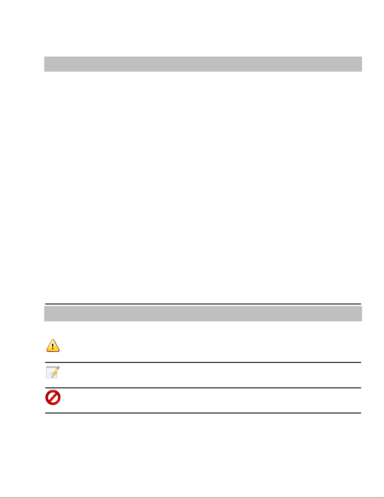
Table of Contents
Section 8: Transmitter Calibration and Troubleshooting................................................................................28
8.0 Calibration ..................................................................................................................................................... 28
8.1 Troubleshooting ............................................................................................................................................ 28
8.2 Power Supply Troubleshooting ..................................................................................................................... 29
8.3 General Troubleshooting............................................................................................................................... 29
Section 9: LTM-350 has HART Protocol ......................................................................................................... 30
9.0 HART Protocol: General Information / Flowchart of HART Menus............................................................... 30
Icon Key
Warning/Caution Valuable Operation Information
Important Information to Know
Read Carefully these Tips are the “DON’Ts” of the instrument.
Section
Warranty
1
1.0 Warranty
All Magtech products are warranted against defects
in materials and workmanship for a period of no
less than one year from the date of shipment. The
level gage chamber and process connections are
guaranteed for the life of the tank or vessel to
which it is attached. Floats are guaranteed for two
years.
discretion those products that fail to perform as
specified
This warranty is in lieu of any other warranty
expressed or implied by any party other than
Magtech. Repairs and/or replacements shall be at
the sole discretion of Magtech based on the terms
and conditions of this warranty. Defective products
shall be returned to the factory prepaid by the
buyer after obtaining a Return Authorization
Number from Magtech. All warranty repairs or
replacements will be performed at the factory in
Pearland, Texas. Surface return freight will be paid
by Magtech. Factory warranties do not include field
service. Field service warranty repairs will be at the
buyer’s expense. Consult Magtech for field service
rates.
Magtech will repair or replace at its
, with the following exceptions:
1. Products repaired or modified by persons
that are not authorized by Magtech.
2. Products subjected to misuse, negligence or
accidents.
3. Products that are connected, installed, or
otherwise used in such a way not in strict
accordance with manufacturer’s
instructions.
All Magtech gages and transmitters should
be unpacked and thoroughly inspected upon
receipt. Gages are shipped FOB factory and
are fully protected against damage or loss
during shipment. Any claims for parts
damaged during shipment should be
submitted within 15 days of receipt of goods
by customer.
We value your opinion and want to better
serve you. Please go our website:
www.isemagtech.com and click the customer
feedback survey option (on the left side of the
screen). Some of the best suggestions for
improvement come from our valued
customers. Let us know how we are doing and
what we can do better to improve your
satisfaction with our product and service.
Any modifications to terms and condition of this
warranty will not be binding unless made in writing
and signed by an authorized agent or official of
Magtech.
1

Section
wwwwwwwwwwwwwwwwwwwww
ww
Transmitter Overview
2
2.0 General Description
The LTM-Series are 2-wire electronic field
instruments, suitable for installation in hazardous
and non-hazardous locations. Testing and
certification has been obtained from different
agencies for installation in such areas. This
instrument is designed to measure and transmit an
analog and/or digital signal proportional to liquid
level in a tank. The complete assembly includes an
explosion-proof enclosure and attached sensor tube
and a magnetic float. The LTM-Series are available
in a variety of lengths and wetted materials to
accommodate many different applications.
2.1 Product Identification
ZZ/ZZ S/N AAAA / OL BBBB
MODEL LTM- 350-G-XXXX
TAG YYYY
ISE-MAGTECH
wwwwwwwwwwwwwwwwwwwwwww
wwwwwwwwwwwwwwwwwwwwwww
Figure 1. Example label/name plate
BBBB = The overall probe length of the instrument.
Note: THIS IS NOT THE MEASURING RANGE.
XXXX = The measuring range of the instrument.
The 0 and 100% (4/20mA) output range.
YYYY = The end user specified tag number (only
when specified).
2.2 Transmitter Configurations
LTM-Series transmitters generally have two
configurations:
Gage Mounted: Where the transmitter is
1.
mounted on the outside of a magnetic level
gage and strategically located within a
certain longitudinal distance from the
transmitter sensor probe and a magnetic
float is placed inside the level gage.
Standalone (or Direction Insertion Type):
2.
Where the transmitter has a magnetic float
directly around the transmitter sensor
probe and the probe is directly inserted into
a tank/vessel.
The product can be identified by the stainless steel
label that is located on the side of the transmitter
enclosure/housing.
The label can be read as follows:
wwww = Any hazardous location area classification
markings that the instrument is approved for.
ZZ/ZZ = Born on date; the2 digit month and 2 digit
year the instrument was shipped to the customer.
AAAA = The specific serial number assigned by
Magtech for complete traceability.
In either configuration as the tank level changes,
the float tracks the change and continuously
activates the sensor probe. The electronics process
the change in signal and output an analog and/or
digital signal. This output is precisely the liquid level
in the tank.
Magtech is always willing to explore
unique applications that require their own
distinctive configurations. Please consult the
factory for guidance.
2
2.3 Gage Mounted Transmitter
2.4 Standalone Transmitter
The LTM-Series may be strapped to the outside of
the Magtech LG series magnetic level gage. In such
an installation, it is used as an accessory transmitter
for the visual level gage. The same float used to
activate the magnetic gage is also used to activate
the magnetostrictive sensor of the LTM and
transmit a directly proportional 4/20mA signal.
The depiction below shows the gage mount
installation of the LTM-Series to a mag-gage. The
transmitters may be calibrated for the same range
as the visual indicator on the mag-gage, or for part
of the range depending on the application.
When a magnetic level gage is not present, the LTM
can be inserted into the tank/vessel with its own
float mounted around the sensor tube.
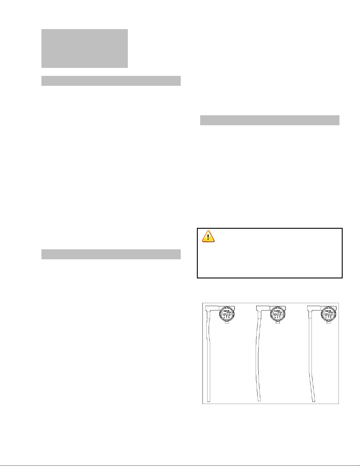
The depictions below show the standalone version
of the LTM-Series with various process connections
and the standard float stop with centering ring.
Figure 3. Transmitters with various process connections.
Figure 2. Gage mounted transmitter
Magtech transmitters may also be used in
conjunction with other manufacturers’
magnetic level gages. Full warranties will apply
upon factory approval. Float and or Indicator
replacement may be required.
In Figure 3:
Transmitter A depicts a standard ¾” compression
fitting that is on all standalone transmitters.
Transmitter B depicts a ¾” compression fitting and
a hex plug. This option is highly recommended
because the hex plug is selected based on the
float’s diameter (OD), so if the instrument ever
needs to be removed or serviced for any reason it
can be removed by the hex plug.
Transmitter C depicts a flanged option with a ¾”
compression fitting and a hex plug.
3
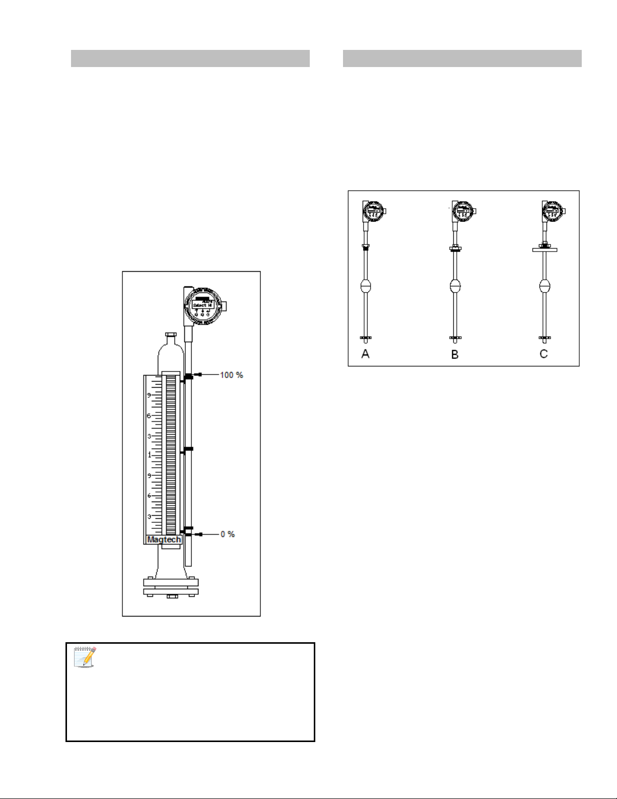
A stilling well may be used along with the
transmitter inside the tank. Stilling-well is a pipe
external to the sensor probe and float encasing the
entire assembly protecting it from surface agitation
or from physical damage due to the length of the
sensor probe. A depiction of a transmitter with a
stilling well is provided below.
Optional Features that are available with the
LTM-350 but
NOT the LTM-250 are:
1. HART Protocol, which enables:
a. A second digital output proportional to
an interface level (requires a second
float of different specific gravity)
b. A digital temperature output that
reflects the liquid temperature.
c. Advanced diagnostics and features
highly beneficial for commissioning,
troubleshooting or monitoring.
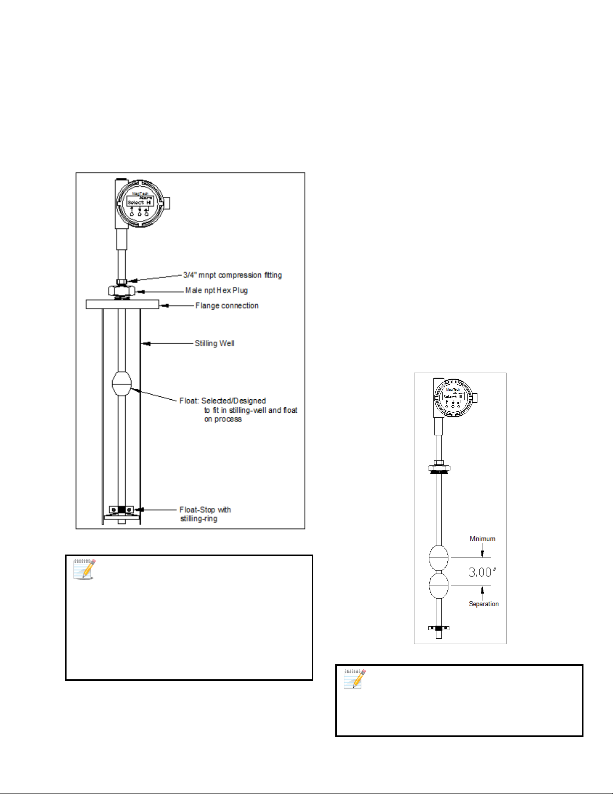
Up to two floats may be used with the LTM-350
only. The second float will typically sense the
interface level (the heavier of the two fluids) in the
tank. The specific gravity of the second float will be
such that it can be totally immersed in the lighter
fluid. The drawing below shows a transmitter with
dual floats, one for total level and the other for
interface level (also available with various process
connections).
Figure 4. Transmitter with a Stilling-well
When a stilling well is used, care should be
exercised when installing the tube to center it in
the chamber so that the float can freely travel
the entire length of the probe. Stilling wells are
required for transmitters over 10 feet or the
instrument cannot be considered under
warranty.
Figure 5. Dual Output Transmitter
A dual output transmitter is also available
in a gage mount configuration. Consult factory
for further details.
4
Section
3
Transmitter Description
3.0 Detailed Description
The LTM-Series is an assembly of two major
components:
The Sensor Tube Assembly: This is a 5/8” diameter
stainless steel probe, sealed on one end, with the
magnetostrictive waveguide in its center. In
addition to the magnetostrictive waveguide, the
tube also houses the optional temperature sensor
and the sensing elements. The tube is made to
lengths of 2-30ft. in rigid construction.
The Enclosure and Electronics: The extruded
aluminum housing has two compartments. The
enclosure is rated NEMA 4X and 7. One side
contains the microprocessor board assembly and
calibration push buttons. The other side contains
the field wiring termination board. The electronics
module is connected to the detector board of the
sensor tube assembly via a plug-in cable. The
electronics module houses printed circuit boards
(PCB) that encompass surface mount component
construction utilizing the latest integrated circuit
technology.
Magtech also has a stainless steel enclosure
that can be utilized. Please contact factory for
further details.
3.1 Technology – Theory of Operation
The LTM-250/350 series level transmitters are
based on the principle of magnetostriction, first
used for digital delay lines and later precision
distance or displacement in the machine tool
industry. This principle, if designed and applied
properly, has potentially very high measurement
resolution, typically better than 0.001 inch. In the
machine tool industry such a high resolution is
desirable. In the level measurement application,
however, a resolution of 0.03 inch is more than
adequate.
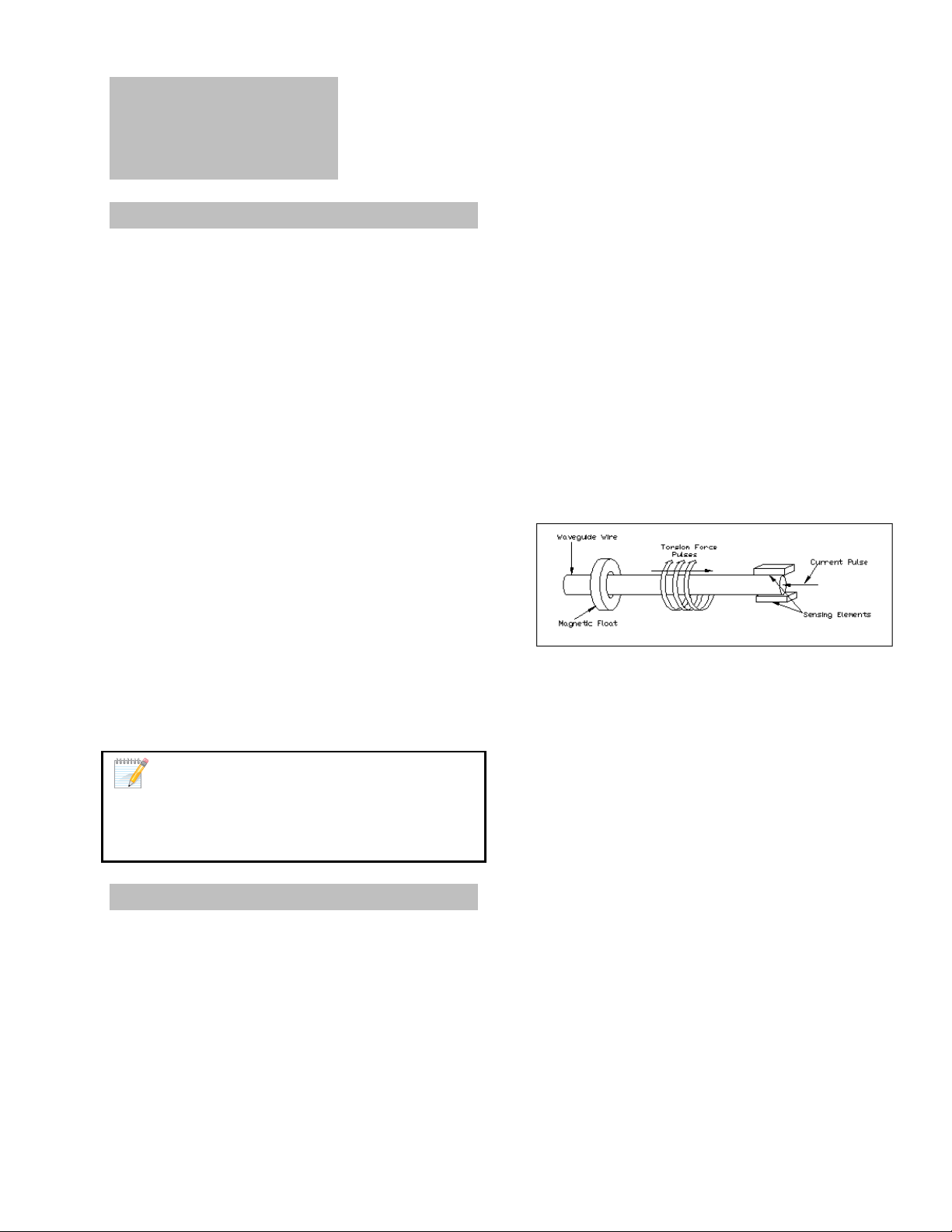
In a brief description, the magnetostrictive principle
consists of a wire extruded and heat treated under
carefully chosen conditions to retain desired
magnetic properties, which is pulsed by a circuit
with a relatively high current pulse. The high
current pulse produces a circular magnetic field as it
travels down the wire at the speed of sound.
Another magnetic field generated by a permanent
magnet (the float), placed near or around the wire
at some distance from the point of entry of this
pulse interferes with the magnetic field of the
current pulse and a torsional force results at the
collision point.
Figure 6. Principle of Operation
The effect of this torsion force is a twist to the wire
at this point producing torsion wave traveling
towards both ends of the wire. The propagation
time (or time-of-flight) of this wave is measured
precisely and if the wire properties remain stable, it
is very repeatable at about 5-10 microseconds per
inch, which is approximately the speed of sound in
that medium. By measuring the exact number of
microseconds it took the torsion wave to reach a
designated termination point of the wire, the
distance to the magnet from this termination point
can be easily calculated.
5
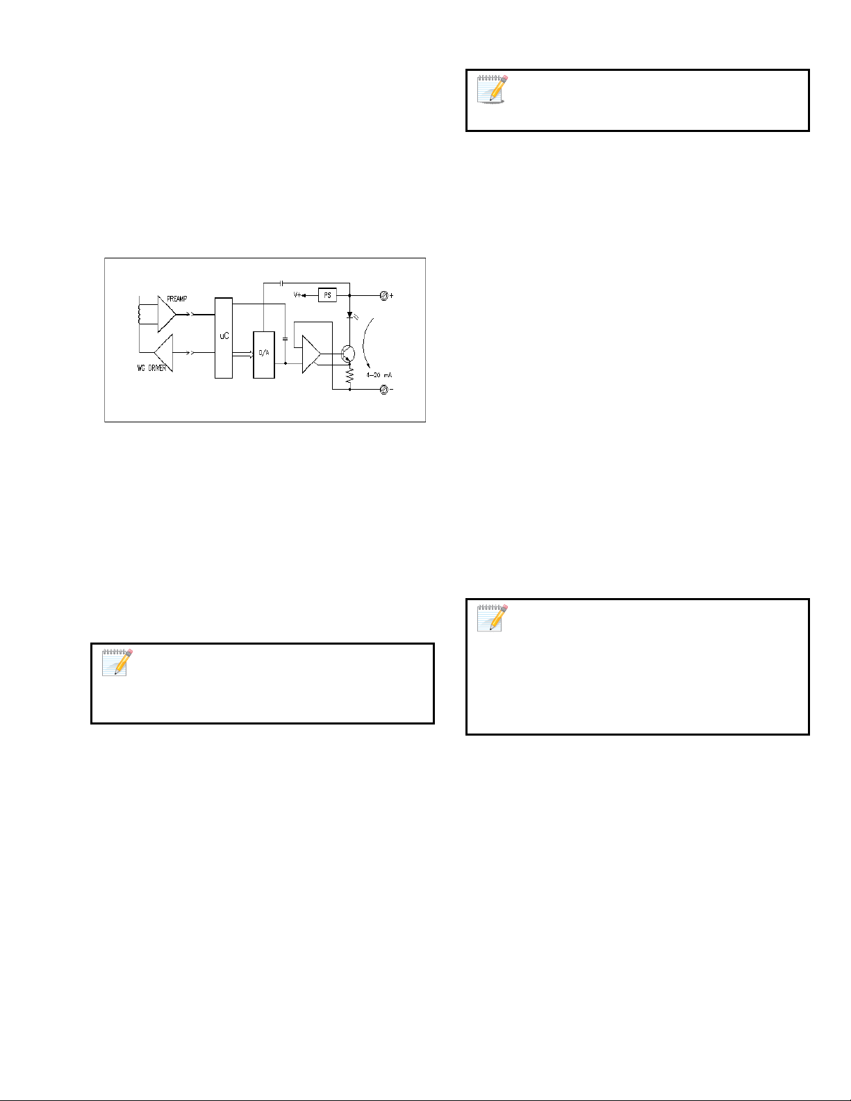
A high-speed microcontroller is utilized in the
design to process and calculate the elapsed time
measurement. Accurate crystals are used for the
time based to resolve sub-microsecond timing
increments. The binary number, equivalent to the
microseconds of the echo travel time is used to
calculate the distance of the float and a
corresponding digital signal is output. A basic block
diagram describing the operation is shown below.
Figure 7. Basic Transmitter Block Diagram
Calibration routines are included in the software to
the 0% and 100% points for any distance desired.
Even reverse calibration is a simple task using the
software routines. Reverse calibration is desirable if
ullage instead of level is required, or when the
probe is installed with bottom mount electronics.
LTM-350, via HART protocol only.
2. Primary Level and Interface Level – A second
float may be added below the first, and the
second output will be calibrated automatically.
The second time interval is timed in the same
manner as the first one and added to the first to
derive the position of the heavier float. The two
floats require a separation of approximately
three inches. The float size, geometry, and
magnetic strength all play a factor in how close
the two floats can be without interfering with
each other.
3. Primary Level and Temperature – An optional
temperature sensor is embedded inside the
bottom tip of the probe, and it is configured to
be the third digital output of the transmitter,
and comes factory calibrated for the operating
range of -50C to 149C (-58F to 300F)
4. Primary Level, Interface Level, and
Temperature
– This options is called a ‘fullblown” unit and offers all three possible
outputs.
LTM-350 transmitter has four output
The
configurations.
Configuration options must be chosen at
quoting stage.
1. Primary Level – The most basic version of this
transmitter is that it computes the distance
between the float and the detector from the
elapsed time measurement. A specific
interrogation pulse is applied to the waveguide.
Any feedback signal received before and after
this window is rejected as noise. Even signals
received during the active window are
evaluated and filtered so that only high integrity
data is accepted. The conditioned signal is
converted to a percent of full-scale number and
a number representing the distance and output
as a digital signal. (LTM-250/350)
A deadband of approximately three inches,
next to the detector, is fixed in the software
and the float is not permitted to enter this
area. If this happens output readings maybe
erratic or go to fail mode.
6
Section
4
4.0 Gage Mount Installation
Installation
The LTM-Series can be mounted to the side of a
Magtech LG series level gage using special mounting
brackets and stainless steel hose clamps. When
mounting the transmitter to an LG series gage the
active sensor region of the probe should fall within
the centerline of the process connections on the
gage. If the transmitter’s deadband region is inside
the centerline of the process connections the
transmitter will not output an accurate
measurement because the active region of the
probe is too short. When placing an order for a
transmitter to accompany an existing gage it is
important to indicate the style of the gage, the
temperature, and the center-to-center dimension.
Calibration of the probe is factory set to the
center-to-center dimensions provided
re-ranging may have to be performed to match the
probe to the desired control room specifications.
See Section 7.1 “Change Range” for more details.
; however a
4.1 Standalone Installation
The LTM-Series standalone transmitter comes
equipped with a ¾” mnpt compression fitting,
mounted approximately 3 to 6 inches below the
electronics housing. The fitting is placed in this area
to ensure the transmitter is calibrated in the sensor
tubes active region. Refer to the standalone
drawings for a visual description of the transmitter
features. Optional configurations are available
upon request (2” mnpt, flanges, etc…). The
magnetic float used in the stand-alone unit is
designed to travel up the sensor tube with the
change in fluid level. If build-up of process or
contaminates should restrict the movement of the
float, the transmitter sensor tube will have to be
cleaned or the float may have to be replaced with
one that has a larger inside diameter. The floats are
designed to match the pressure and specific gravity
for the process being measured and come in various
materials ranging from stainless to kynar. The
magnetic float can be changed out at any time to
accommodate the processes being measured. The
float stop, located at the bottom of the
transmitters, can be removed to allow the float to
slide off the sensor tube.
4.2 General Installation Guidelines
The basic steps to installing the LTMs are:
1. Inspection of equipment: Inspect the parts
that are listed on the packing slip. Make sure
nothing appears to be damaged such as a
broken glass from the level indicator assembly
(flippers), damaged float, or a damaged
transmitter. Please file a claim with the
shipping company immediately if it is believed
the shipment has arrived damaged and be
prepared to provide pictures.
The sensor probe of the transmitter
SHOULD NOT BE BENT, BOWED, OR KINKED in
any way or the transmitter will not work (will
most likely go into fail mode).
The following is a depiction of damaged probes:
Figure 8. All damaged sensor probes
7

2. Identify Proper Orientation of Transmitter:
There are a few possible orientations of the
LTM Series transmitters, they are:
Do not over tighten the clamps because
they will bend and distort.
Figure 10. Top view of mounting clamps and sensor probe
Figure 9. Possible transmitter configurations
Transmitter A is a standard top mount
configuration.
Transmitter B is a top mount with elbow, usually
utilized when there are temperature or head room
issues. There is also a bottom mount with elbow
configuration which is not depicted.
Transmitter C is a bottom mount transmitter with
remote electronics. This configuration is utilized in
more extreme temperatures or for accessibility.
There is also top mount with remote electronics
which is not depicted.
3. Mounting the Transmitter. Align the 4/20 mA
(or 0 and 100%) markings with the center of the
top and bottom process connection. Mount the
transmitter along the level gage and use a nut
driver to tighten the clamps so the sensor probe
of the transmitter is held securely (will not slip
up and down). Keep the transmitter supported
while the clamps are being tightened (this can
require more than one person).
A: Is the correct way to have clamps tightened.
The clamps do not have to meet.
B: Is incorrect because the clamp is flipped around
and will not grip the sensor probe.
C: Is incorrect because the clamp has been tighten
too much and damaged/distorted.
Effects of high vibration can be minimized
early on by notifying the factory at time of
order. The electronics can be remote mounted
and special insulators can be installed. Please
see the depiction below.
Figure 11. Insulator for high vibration
8
 Loading...