


Instruction Manual
Form 5497
January 2014
299H Series
299H Series Pressure Reducing Regulators
!WARNING
Failure to follow these instructions or to properly install and maintain this equipment could result in an explosion and/or fire causing property damage and personal injury or death.
Fisher® regulators must be installed, operated and maintained in accordance with federal, state and local codes, rules and regulations and Emerson Process Management Regulator Technologies, Inc. (Regulator Technologies) instructions.
If the regulator vents gas or a leak develops in the system, service to the unit may be required. Failure to correct trouble could result in a hazardous condition.
Call a gas service person to service the unit. Only a qualified person must install or service the regulator.
Introduction
Scope of the Manual
This Instruction Manual provides installation, adjustment and maintenance instructions and parts ordering information for the 299H Series regulators. Complete instructions and parts list for the 67C Series filtered pilot supply regulator and other Fisher equipment are found in separate instruction manuals.
Description
The 299H Series pressure reducing regulators provide a broad capacity of controlled pressure ranges and capacities in a wide variety of distribution, industrial and commercial applications. A 299H Series regulator has a pilot integrally mounted to the actuator casing. The 299H Series regulators can handle inlet pressures up to 175 psi / 12.1 bar depending on orifice size.
W7513
Figure 1. 299H Series Pressure Reducing Regulator
The integral token relief on the Types 299HR and 299HSR regulators is located in the pilot and opens to relieve minor overpressure.
The Type 299HS provides overpressure or overpressure and underpressure protection by completely shutting off the flow of gas to the downstream system. It comes with a Type VSX-2 slam-shut device which can be configured for Ovepressure Shutoff (OPSO) or Overpressure and Underpressure Shutoff (OPSO/UPSO). The slam-shut device’s actions are independent of the main valve and of variations to the inlet pressure. The Type VSX-2 slam-shut device has internal or external registration. External registration requires a downstream sensing line.
D102684X012
www.fisherregulators.com

299H Series
Specifications
Specifications for 299H Series constructions are given below. Some specifications for a given regulator as it originally comes from the factory are stamped on a nameplate located on the actuator upper casing.
Available Constructions
Type 299H: Pilot-operated pressure reducing regulator with a pilot integrally mounted to the actuator casing.
Type 299HR: A Type 299H with a token internal relief valve to relieve minor overpressure caused by thermal expansion.
Type 299HS: Same as the Type 299H with a Type VSX-2 slam-shut valve which provides overpressure or overpressure and underpressure protection.
Type 299HSR: Same as the Type 299HS with an internal token relief valve.
Body Size and End Connection Styles
See Table 1
Maximum Operating Inlet Pressureby Orifice Size(1)
1/4 x 3/8-inch / 6.4 x 9.5 mm.......... |
175 psig / 12.1 bar |
3/8 inch / 9.5 mm........................... |
175 psig / 12.1 bar |
1/2 inch / 13 mm............................ |
175 psig / 12.1 bar |
3/4 inch / 19 mm............................ |
150 psig / 10.3 bar |
7/8 inch / 22 mm(5)........................... |
125 psig / 8.6 bar |
1 inch / 25 mm(5)................................. |
100 psig / 6.9 bar |
1-3/16 inches / 30 mm(5).................... |
80 psig / 5.5 bar |
Maximum Casing and Emergency Outlet Pressure(1)
66 psig / 4.5 bar
Outlet (Control) Pressure Ranges(1)(2)
See Table 2
Maximum Set Pressure for Type 299HS(1)
16 psig / 1.1 bar
Maximum Set Pressure for Slam-Shut Device(1)
23 psig / 1.6 bar
Minimum and Maximum Trip Pressure Ranges
See Table 3
Type VSX-2 Sensing Line Connection
1/4 NPT
Pressure Control Accuracy (Fixed Factor)(PFM)
±1%(3) of absolute control pressure
Minimum Differential Pressure For Full Stroke
1.5 psid / 0.10 bar d
Control Line Connections
3/4 NPT
Temperature Capabilities(1)
-20 to 150°F / -29 to 66°C
Approximate Weight
21 pounds / 10 kg
Pressure Registration
Internal, External or Dual Registration
See Figure 2
Fixed Restriction Sizes
0.044 inch / 1.1 mm, Red (standard gain)
0.071 inch / 1.8 mm, Green (low gain)
0.082 inch / 2.1 mm, Blue (lower gain)
Options
•Filter(3): A P590 Series filter installed in the pilot supply tubing between main body and pilot
•Filtered pilot supply regulator(3)(4):A Type 67CF supply regulator with integral 5 micron
Polyethylene filter
1.The pressure/temperature limits in this Instruction Manual and any applicable standard or code limitation should not be exceeded.
2.For optimum performance, a pilot supply regulator may be installed in the pilot supply tubing between the main valve and pilot.
3.A pilot supply regulator or a P590 Series filter (only one may be used, not both) may be ordered with the Type 299H, but not both.
4.For inches w.c., use a pilot supply regulator if actual inlet pressure varies more than ±20 psi / ±1.4 bar and published accuracy is required.
5.This orifice size is not available for Types 299HS and 299HSR.
Table 1. Body Sizes and End Connection Styles
BODY SIZE, |
BODY MATERIAL AND END CONNECTION STYLE |
||
INCH / DN |
Cast Iron (For Types 299H and 299HR only) |
Ductile Iron |
Steel (For Types 299H and 299HR only) |
|
|||
|
|
|
|
1-1/4 |
NPT |
- - - - |
- - - - |
1-1/2 |
NPT |
NPT |
NPT |
|
|
|
|
2 / 50 |
NPT and CL125 FF(1) flanged |
NPT, CL125 FF and CL250 RF flanged |
NPT and CL150 RF flanged |
|
|
and PN 10/16 flanged |
|
1. This flange is available with a face-to-face dimension of 7.5 inches / 190 mm or 10 inches / 254 mm.
2

|
|
|
|
|
|
|
|
|
299H Series |
|
||
|
|
|
|
Table 2. Outlet Pressure Ranges |
|
|
|
|
|
|
||
|
|
|
|
|
|
|
|
|
|
|
|
|
|
|
|
TYPE |
|
PILOT CONTROL SPRING |
|
|
|||||
OUTLET (CONTROL) |
|
|
|
|
|
|
|
|
|
|
|
|
|
|
|
|
|
|
|
|
|
|
|
||
PRESSURE RANGE |
299H |
|
299HR, |
Part Number |
Color |
Free Length |
|
Wire Diameter |
|
|||
|
|
|
299HS and |
|
|
|
|
|
|
|||
|
|
|
|
299HSR |
|
|
|
|
|
|
|
|
Inch w.c. |
mbar |
|
|
|
|
Inch |
mm |
|
Inch |
mm |
|
|
|
|
|
|
|
|
|
||||||
|
|
|
|
|
|
|
|
|
|
|
|
|
3.5 to 6(1) |
9 to 15(1) |
X |
|
X |
T13707T0012 |
Black |
1.86 |
47.2 |
|
0.055 |
1.40 |
|
5 to 9(1) |
12 to 22(1) |
X |
|
X |
T13589T0012 |
Yellow |
2.05 |
52.1 |
|
0.051 |
1.30 |
|
7 to 20(1) |
17 to 50(1) |
X |
|
X |
1N3112X0012 |
Unpainted |
2.18 |
55.4 |
|
0.075 |
1.90 |
|
16 to 40(1) |
40 to 99(1) |
X |
|
X |
1B413727222 |
Purple |
2.12 |
53.8 |
|
0.092 |
2.34 |
|
1 to 3.25 psig |
69 mbar to 0.22 bar |
X |
|
X |
T13593T0012 |
Light blue |
2.12 |
53.8 |
|
0.105 |
2.67 |
|
2.75 to 6 psig |
0.19 to 0.41 bar |
X |
|
X |
T13671T0012 |
Orange |
2.40 |
61.0 |
|
0.120 |
3.05 |
|
5 to 16 psig |
0.34 to 1.1 bar |
X |
|
X |
T13600T0012 |
Red |
2.10 |
53.3 |
|
0.142 |
3.61 |
|
14 to 35 psig |
0.97 to 2.4 bar |
X |
|
- - - - |
19B0432X012 |
Zinc |
2.15 |
54.6 |
|
0.207 |
5.26 |
|
30 to 60 psig |
2.1 to 4.1 bar |
X |
|
- - - - |
19B0432X022 |
Green |
2.75 |
69.8 |
|
0.225 |
5.71 |
|
|
|
|
|
|
|
|
|
|
|
|
|
|
1. Use a pilot supply regulator if actual inlet pressure varies more than ±20 psi / ±1.4 bar and the published accuracy is required.
Table 3. Type VSX-2 High and Low Trip Pressure Ranges
|
SLAM-SHUT |
FOR USE WITH MAIN VALVE |
MINIMUM TO MAXIMUM |
TYPE VSX-2 |
SPRING FREE |
SPRING WIRE |
||||||
RANGE |
SPRING RANGE |
|
TRIP PRESSURE |
SPRING PART |
LENGTH |
DIAMETER |
||||||
REGISTRATION |
|
|||||||||||
|
|
Inch w.c. |
mbar |
|
Inch w.c. |
mbar |
NUMBER |
Inch |
mm |
Inch |
mm |
|
|
|
3.5 to 6 |
9 to 15 |
12 to 25 |
30 to 62 |
T14162T0012 |
3.15 |
80.0 |
0.07 |
1.70 |
||
|
|
5 to 9 |
12 to 22 |
|||||||||
|
|
|
|
|
|
|
|
|
||||
|
|
3.5 to 6 |
9 to 15 |
|
|
|
|
|
|
|
||
|
|
5 to 9 |
12 to 22 |
20 to 52 |
50 to 129 |
T14163T0012 |
3.15 |
80.0 |
0.08 |
2.03 |
||
|
|
7 to 20 |
17 to 50 |
|
|
|
|
|
|
|
||
High |
Internal or |
7 to 20 |
17 to 50 |
1.4 to 3.9 psig |
97 to 269 |
T14164T0012 |
3.15 |
80.0 |
0.09 |
2.31 |
||
Pressure |
16 to 40 |
40 to 99 |
||||||||||
External |
|
|
|
|
|
|
|
|||||
Trip |
16 to 40 |
40 to 99 |
|
|
|
|
|
|
|
|||
|
|
|
|
|
|
|
|
|||||
|
|
|
|
|
|
|
|
|
||||
|
|
1 to 3.25 psig |
69 mbar to 0.22 bar |
3.8 to 8.7 psig |
262 to 600 |
T14165T0012 |
3.15 |
80.0 |
0.12 |
3.05 |
||
|
|
2.75 to 6 psig |
0.19 to 0.41 bar |
|
|
|
|
|
|
|
||
|
|
2.75 to 6 psig |
0.19 to 0.41 bar |
5.8 to 16 psig |
400 to 1103 |
T14166T0012 |
3.15 |
80.0 |
0.14 |
3.51 |
||
|
|
5 to 16 psig |
0.35 to 1.1 bar |
|||||||||
|
|
|
|
|
|
|
|
|
||||
|
|
5 to 16 psig |
0.35 to 1.1 bar |
11.6 to 23 psig |
800 to 1586 |
T14167T0012 |
3.15 |
80.0 |
0.17 |
4.32 |
||
|
|
5 to 9 |
12 to 22 |
2 to 12 |
5 to 30 |
T14168T0012 |
3.15 |
80.0 |
0.04 |
1.09 |
||
|
|
7 to 20 |
17 to 50 |
|||||||||
|
|
|
|
|
|
|
|
|
||||
|
|
7 to 20 |
17 to 50 |
4 to 30 |
10 to 75 |
T14169T0012 |
3.15 |
80.0 |
0.06 |
1.40 |
||
|
External |
16 to 40 |
40 to 99 |
|||||||||
|
|
|
|
|
|
|
|
|||||
|
1 to 3.25 psig |
69 mbar to 0.22 bar |
0.36 to 2.3 psig |
25 to 159 |
T14170T0012 |
3.15 |
80.0 |
0.07 |
1.70 |
|||
|
|
|||||||||||
|
|
2.75 to 6 psig |
0.19 to 0.41 bar |
|||||||||
|
|
|
|
|
|
|
|
|
||||
|
|
2.75 to 6 psig |
0.19 to 0.41 bar |
1.5 to 10.8 psig |
103 to 745 |
T14171T0012 |
3.15 |
80.0 |
0.13 |
3.17 |
||
|
|
5 to 16 psig |
0.35 to 1.1 bar |
|||||||||
|
|
|
|
|
|
|
|
|
||||
Low |
|
5 to 9(1) |
12 to 22(1) |
|
|
|
|
|
|
|
||
Pressure |
|
7 to 20(1) |
17 to 50(1) |
- - - - |
- - - - |
- - - - - - - - - - - |
- - - - |
- - - - |
- - - - |
- - - - |
||
Trip |
|
|
|
|
|
|
|
|
|
|
||
|
16 to 40(1) |
40 to 99(1) |
|
|
|
|
|
|
|
|||
|
|
1 to 3.25 psig(2) |
69 mbar to |
70% of regulator |
70% of regulator |
|
|
|
|
|
||
|
|
0.22 bar |
(2) |
T14170T0012 |
3.15 |
80.0 |
0.07 |
1.70 |
||||
|
|
|
|
setpoint to |
setpoint to |
|||||||
|
Internal |
2.75 to 6 psig(2) |
0.19 to 0.41 bar(2) |
2.3 psig |
159 mbar |
|
|
|
|
|
||
|
|
|
|
|
70% of regulator |
70% of regulator |
|
|
|
|
|
|
|
|
2.75 to 6 psig(2) |
0.19 to 0.41 bar(2) |
setpoint to |
setpoint to |
T14171T0012 |
3.15 |
80.0 |
0.13 |
3.17 |
||
|
|
|
|
|
10.8 psig |
745 mbar |
|
|
|
|
|
|
|
|
|
|
|
75% of regulator |
75% of regulator |
|
|
|
|
|
|
|
|
5 to 16 psig(3) |
0.35 to 1.1 bar(3) |
setpoint to |
setpoint to |
T14171T0012 |
3.15 |
80.0 |
0.13 |
3.17 |
||
|
|
|
|
|
10.8 psig |
745 mbar |
|
|
|
|
|
|
1. Low Pressure Trip cannot be used with this main valve spring range for an internally registered Type VSX-2 to provide underpressure shutoff under flowing conditions. If protection against loss of inlet pressure is the only required function for the Type VSX-2 then an internally registered Type VSX-2 may be used with the same minimum trip pressures as an externally registered Type VSX-2.
2. 70% of regulator setpoint is the minimum allowable Low Pressure Trip setting for an internally registered Type VSX-2 used with this main valve spring range. If protection against loss of inlet pressure is the only required function for the Type VSX-2 then an internally registered Type VSX-2 may be used with the same minimum trip pressures as an externally registered Type VSX-2.
3. 75% of regulator setpoint is the minimum allowable Low Pressure Trip setting for an internally registered Type VSX-2 used with this main valve spring range. If protection against loss of inlet pressure is the only required function for the Type VSX-2 then an internally registered Type VSX-2 may be used with the same minimum trip pressures as an externally registered Type VSX-2.
Note: Other spring combinations are available, please contact your local Sales Office for additional information.
3

299H Series
|
|
|
B |
|
|
|
J |
|
|
|
OUTLET |
|
E |
|
|
|
H |
|
|
|
|
|
J |
|
|
|
|
3/4 NPT |
|
|
|
|
DOWNSTREAM |
G |
|
|
|
CONTROL LINE |
|
|
|
|
CONNECTION |
EXTERNAL REGISTRATION |
|
|
|
|
|
|
|
3/4 NPT |
|
|
|
INLET |
CONTROL LINE |
|
|
|
CONNECTION |
PILOT SUPPLY |
|
|
|
|
|
||
|
|
|
|
|
|
|
|
SCREEN |
|
|
|
G |
|
|
|
|
K |
C |
|
|
|
A |
|
|
|
|
F |
J |
|
|
|
|
|
|
|
|
|
3/4 NPT |
|
|
|
|
DOWNSTREAM |
G |
|
|
|
CONTROL LINE |
|
|
|
INTERNAL |
|
|
|
|
CONNECTION |
DUAL REGISTRATION |
|
E0070 |
|
REGISTRATION |
|
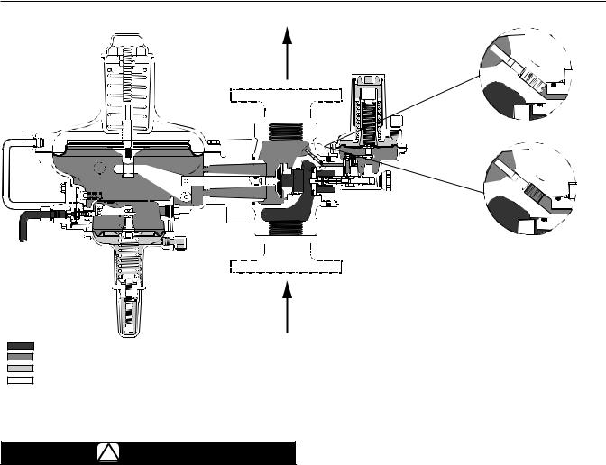
INLET PRESSURE
OUTLET PRESSURE
ATMOSPHERIC PRESSURE
LOADING PRESSURE
TYPE 299H
A7272 |
A7272 |
|
|
TOKEN RELIEF CLOSED |
TOKEN RELIEF OPEN |
|
TYPE 299HR (TOKEN RELIEF DETAIL) |
Figure 2. 299H Series Operational Schematics
4
299H Series
E0069
EXTERNAL REGISTRATION
E0070
INTERNAL REGISTRATION
E0072
INLET PRESSURE
OUTLET PRESSURE ATMOSPHERIC PRESSURE LOADING PRESSURE
TYPE 299HS
Figure 2. 299H Series Operational Schematics (continued)
Principle of Operation
!WARNING
Since a pilot-operated regulator is constructed of both a pilot and a main valve, do not exceed the maximum inlet pressure shown on the nameplate.
Letter keys in this section refer to Figure 2 unless otherwise noted. Fast response and accuracy are made possible by the amplifying effect of the pilot and by the two-path control system. The function of the pilot is to sense change in the controlled pressure and amplify it into a larger change in the loading pressure. Any changes in outlet pressure act quickly on both the actuator diaphragm and the loading pilot, thus providing the precise pressure control that is characteristic of a two-path control system.
Upstream or inlet pressure is utilized as the operating medium, which is reduced through pilot operation to load the main diaphragm chamber. Tubing connects the inlet pressure to the pilot. Downstream or outlet pressure registers underneath the main diaphragm (E) and on top of pilot diaphragm (F). There are three different versions of pressure registration for the 299H Series.
Internal registration—Outlet pressure is registered through the throat (J) to the main diaphragm chamber and then through a small port (G) to the top of the pilot diaphragm.
External registration—The throat (J) is blocked and a downstream control line is connected to the pilot upper diaphragm chamber or the actuator lower diaphragm chamber. A small port (G) connects the two chambers.
Dual registration—The lower main diaphragm chamber registers outlet pressure through the throat (J) and the upper pilot diaphragm chamber registers downstream pressure by using a downstream control line. The port (G) between the chambers is blocked.
Type 299H
In operation, assume the outlet pressure is less than the setting of the pilot control spring (A). The top side of pilot diaphragm assembly (F) will have a lower pressure than the setting of the control spring (A). The control spring (A) forces the diaphragm assembly upward, opening the pilot orifice (C). Additional loading
pressure is supplied from the pilot orifice to the top side of the main diaphragm (E).
5

299H Series
This creates a higher pressure on the top side of the main diaphragm (E) than on the bottom side, forcing the diaphragm downward. This motion is transmitted through a lever, which pulls the valve disk (K) open, allowing inlet pressure to flow through the valve.
When the demand in the downstream system has been satisfied, the outlet pressure increases. The increased pressure is transmitted through the downstream control line (for external or dual registration) or through the port (G) (for internal registration) and acts on top of the pilot diaphragm (F). This pressure exceeds the pilot spring setting and forces the diaphragm down, closing the orifice (C). The loading pressure acting on the main diaphragm (E) bleeds to the downstream system through a bleed restriction (H).
With a decrease in loading pressure on top of the main diaphragm (E), the main closing spring (B) exerts an upward force on the diaphragm post which is connected to the main diaphragm (E), pulling it upward. This moves the main valve disk (K) toward its seat, decreasing flow to the downstream system.
Type 299HR
During normal operation the Type 299HR performance is identical to the Type 299H. If an overpressure condition occurs, the pilot diaphragm head will separate from the pilot diaphragm post and travel until it contacts the pilot spring case. The movement of the diaphragm head creates a path and a token or small amount of gas will be released.
When the overpressure condition ceases, the pilot diaphragm head will return to the diaphragm post and the regulator will return to normal operation.
Type 299HS
The Type VSX-2 slam-shut device on the Type 299HS regulator is a fast acting slam-shut valve which provides overpressure or overpressure and underpressure protection by completely shutting off the flow of gas to the downstream system. The slam-shut module’s actions are independent of the Type 299HS main regulator and of the variations to the inlet pressure. The Type VSX-2 has internal or external registration. External registration requires a downstream sensing line.
The slam-shut disk is held in the open position (reset position) by a small ball holding the disk stem. If
the pressure below the diaphragm increases (or decreases) reaching the Type VSX-2 setpoint, the diaphragm will travel upwards (or downwards) operating a lever which in turn releases the ball.
Once the ball is released, the spring force on the stem will push the stem and disk to the closed position against the seat shutting off all gas flow. The pilot supply pressure is also shut off when the Type VSX-2 is closed. The manual reset has an internal bypass to equalize the reset pressure on either side on the slam-shut disk.
In order for the Underpressure Shutoff (UPSO) of any slam shut to be triggered, the downstream pipe pressure must drop below the UPSO setpoint. In the case of a downstream line break, numerous factors can prevent the downstream pipe pressure from
decreasing below the slam-shut UPSO setpoint. These factors include the distance of pipe to the break, the diameter of the pipe, size of the break and the number of restrictions, such as valves, elbows and bends, downstream of the regulator and/or slam-shut device. Due to these factors additional protections should be installed to stop flow in the event of a line break.
Overpressure Protection
Like most regulators, the Type 299H has outlet pressure ratings lower than the inlet pressure ratings. Complete downstream overpressure protection is needed if the actual inlet pressure exceeds the outlet pressure rating.
Overpressure protection for internal parts is built into the main and pilot diaphragms by means of a small spring on each post. The springs will allow the diaphragm heads to move farther on the posts avoiding damage to or bending of the valve trim.
Overpressuring any portion of a regulator or associated equipment may cause leakage, parts damage or personal injury due to bursting of pressure-containing parts or explosion of accumulated gas. Regulator operation within ratings does not preclude the possibility of damage from external sources or from debris in the pipeline. A regulator should be inspected for damage periodically and after any overpressure condition.
The pilot vent is provided with a 1/4 NPT tapped connection in the spring case.
Installation
!WARNING
Personal injury, equipment damage or leakage due to escaping gas or bursting of pressure-containing parts might result
6
 Loading...