Emerson 5081C-HT User Manual

Instruction Sheet |
5081C-HT |
LIQ_MAN_ABR_5081C-HT/Rev.G |
January 2015 |
|
|
Remote Controlled HART® SMART™ |
|
Two-Wire Conductivity Transmitter |
|
ESSENTIAL INSTRUCTIONS
Read this page before proceeding!
Your purchase from Rosemount Analytical, Inc. has resulted in one of the finest instruments available for your particular application. These instruments have been designed, and tested to meet many national and international standards. Experience indicates that its performance is directly related to the quality of the installation and knowledge of the user in operating and maintaining the instrument. To ensure their continued operation to the design specifications, personnel should read this manual thoroughly before proceeding with installation, commissioning, operation, and maintenance of this instrument. If this equipment is used in a manner not specified by the manufacturer, the protection provided by it against hazards may be impaired.
•Failure to follow the proper instructions may cause any one of the following situations to occur: Loss of life; personal injury; property damage; damage to this instrument; and warranty invalidation.
•Ensure that you have received the correct model and options from your purchase order. Verify that this manual covers your model and options. If not, call 1-800-854-8257 or 949-757-8500 to request correct manual.
•For clarification of instructions, contact your Rosemount representative.
•Follow all warnings, cautions, and instructions marked on and supplied with the product.
•Use only qualified personnel to install, operate, update, program and maintain the product.
•Educate your personnel in the proper installation, operation, and maintenance of the product.
•Install equipment as specified in the Installation section of this manual. Follow appropriate local and national codes. Only connect the product to electrical and pressure sources specified in this manual.
•Use only factory documented components for repair. Tampering or unauthorized substitution of parts and procedures can affect the performance and cause unsafe operation of your process.
•All equipment doors must be closed and protective covers must be in place unless qualified personnel are performing maintenance.
•If this equipment is used in a manner not specified by the manufacturer, the protection provided by it against hazards may be impaired.
WARNING
Substitution of components may impair Intrinsic Safety or suitability for division 2.
WARNING
do not remove or replace while circuit is live unless area is known to be non-hazardous.
WARNING
explosion Hazard - do not disconnect equipment unless area is known to be non-hazardous.
WARNING
To prevent ignition of flammable or combustible atmospheres, disconnect power before servicing or understand and adhere to the manufacturer's live maintenance procedures.
SpeCIAl CoNdITIoN FoR INTRINSICAlly SAFe USe
The 5081 enclosure is made of aluminum alloy and given a protective polyurethane finish; however, care must be taken to protect it from impact, abrasion or friction with other metal surfaces if located in zone 0.
WARNING
If a Model 475 Universal Hart® Communicator is used with these transmitters, the software within the Model 475 may require modification.
If a software modification is required, please contact your local Fisher-Rosemount Service Group or National Response Center at 1-800-654-7768.

5081C-HT |
Instruction Sheet |
January 2015 |
LIQ_MAN_ABR_5081C-HT/Rev.G |
|
|
Specifications
pHySICAl SpeCIFICATIoNS
Housing: Cast aluminum with epoxy coating. Type 4X (IP65). Neoprene O-ring cover seals. 160.5 mm x 175.3 mm x 161.3 mm (6.3 in. x 6.9 in. x 6.4 in.)
diameter: 155.4 mm (6.1 in.)
electrical Conduit openings: 3/4 in. FNPT
power Supply and load: A minimum loop resistance (load) of 250 ohms and a minimum power supply of 18 volts DC is required for digital communication as shown in the load/power supply graph below.
local Readout:
Main Display is 4 digits, 20 mm tall (0.8 in.) Message Display is ten digits, 7 mm tall (0.3 in.)
Automatic Temperture Compensation
3-wire Pt100 RTD
Conductivity: 0 to 200 °C (32 to 392 °F) % concentration: 0 to 100 °C (32 to 212°F)
Low Conductivity: 0 to 100 °C (32 to 212 °F) Ambient temperature: -20 to 65° C (-4 to 149° F) Relative Humidity: 0-95% with enclosure sealed.
Ce: eMI/RFI certified: EN61326
HAzARdoUS AReA ClASSIFICATIoN: Intrinsic Safety:
Class I, II, III, Div. 1 Groups A-G
T4 Tamb = 70°C, = 62°C (-FF)
Exia Entity
Class I, Groups A-D
Class II, Groups E-G Class III
T4 Tamb = 70°C
|
IECEx BAS 09.0159X |
|
Ex ia IIC T4 Ga |
ATEX |
0600 II 1 G |
|
Baseefa03ATEX0099 |
|
EEx ia IIC T4 |
|
Tamb = -20°C to +65°C |
Non-Incendive:
Class I, Div. 2, Groups A-D Dust Ignition Proof
Class II & III, Div. 1, Groups E-G Type 4X Enclosure
Class I, Div. 2, Groups A-D
Suitable for Class II, Div. 2, Groups E-G T4 Tamb = 70°C
explosion-proof:
Class I, Div. 1, Groups B-D
Class II, Div. 1, Groups E-G Class III, Div. 1
Class I, Groups B-D
Class II, Groups E-G
Class III
Tamb = 65°C max
TRANSMITTeR SpeCIFICATIoNS @ 25°C
Measured Range*: 0-20,000 µS/cm
Accuracy: ± 0.5% of reading and ± 0.001 µS/cm Repeatability: ± 0.25% of reading
Stability: 0.25% of output range/month, non-cumulative
Ambient Temperature Coefficient: ± 0.05% of reading/°C
Temperature Slope Adjustment: 0-5%/° C
Other temperature compensation algorithms: ultra-pure water compensation, cation conductivity, or raw (uncompensated) conductivity.
Compatible RTd: 100Ω or 1000Ω with Automatic Recognition
loop SpeCIFICATIoNS
loop Accuracy: Under controlled laboratory conditions at 25°C (77°F) with perfectly calibrated ENDURANCE sensor of appropriate cell constant:
up to 5,000 µS/cm: ± 1.0% and ± 2 least significant digit
from 5,000 to 20,000: ± 2% of reading and ± 2 least significant digit
SeNSoR SeleCTIoN GUIdelINeS
Cell Constant |
Suggested Conductivity Range |
0.01/cm |
up to 50 µS/cm |
0.1/cm |
1.0 to 500 µS/cm |
1.0/cm |
10 to 20,000 µS/cm |
Note: The conductivity values shown in the above chart are for UNCOMPENSATED (or RAW) conductivity at 25°C. Maximum range values will vary due to temperature compensation selection, process temperature, and other process conditions.
2

Instruction Sheet |
5081C-HT |
LIQ_MAN_ABR_5081C-HT/Rev.G |
January 2015 |
|
|
INFRARed ReMoTe CoNTRolleR
1.Pressing a menu key allows the user access to calibrate, program, or diagnostic menus.
2.Press ENTER to store data and settings. Press NEXT to move from one submenu to the next. Press EXIT to leave without storing changes.
3.Use the editing keys to scroll through lists of allowed settings or to change a numerical setting to the desired value.
4.Pressing HOLD puts the transmitter in hold and sends the output current to a pre-programmed value. Pressing RESET causes the transmitter to abandon the present operation and return to the main display.
FIGURe 1. Infrared remote controller
ReSeT - Press RESET to end the current operation and return to the main display. Changes will NOT be saved. ReSeT does
NoT return the transmitter to factory default settings.
ARRoW KeyS - Use é and ê keys to  increase or decrease a number or to scroll through items in a list. Use the ç or è
keys to move the cursor across a number. A flashing word or numeral shows the position of the cursor.
CAl - Press CAL to access the calibration menu.
pRoG - Press PROG to access the program menu.
dIAG - Press DIAG to read diagnostic messages.
Hold - Press HOLD to access the prompts used for turning on or off the hold function.
eNTeR - Press ENTER to move from a submenu to the first prompt under the submenu. Pressing ENTER also stores changes in memory and advances to the next prompt.
NeXT - Press NEXT to advance to the next submenu or to leave a message screen.
 eXIT - Press EXIT to end the current operation. Changes are NOT saved.
3

5081C-HT |
Instruction Sheet |
January 2015 |
LIQ_MAN_ABR_5081C-HT/Rev.G |
|
|
FIGURe 2. Menu Tree
CAlIbRATIoN
|
|
|
process display |
|
pRoGRAM |
|
||
|
|
|
5081C-HT
Process Display Screen
5000µS/cm
25.0C 12.00mA
CAL key |
|
dIAGNoSTICS |
PROG key |
|
|
|
|
|
DIAG key |
|
|
|
|
|
HOLD key |
|
|
1 Not available with display in Neutral Salt, Cation, or Resistivity modes.
CALIbrAtE
SEnSOr 0
tEMP AdJ
Mtr CAL
CELL
tEMP
OUtPUt
OutPut
tEMP
dISPLAY
HArt
SEtUP
dEFAULT
AbS C
0 air
CELL COnSt
tSLOPE1
CAL F
5081-C-Ht
SoFt
HArd
FaULTs
pRoGRAM MeNU MNeMoNICS
|
OUtPUt |
Current output menu header |
|
4MA |
4mA current output (setpoint) |
|
20MA |
20mA current output (setpoint) |
|
HoLd |
Current output on hold |
|
FAULt |
Fault condition current output setting |
|
dPn |
Current output dampening time |
|
tESt |
Current output test value |
|
tEMP |
Temperature menu header |
|
tAUtO |
Automatic temperature compensation |
|
tMAn |
Manual temperature compensation input |
|
dISPLAY Display menu header |
|
|
tYP |
Conductivity measurement type |
|
tEMP |
°C / °F toggle selection |
|
OUtPUt |
Current (mA) or percent of full scale display |
4 |
COdE |
Security code |
|
|
|

Instruction Sheet |
5081C-HT |
LIQ_MAN_ABR_5081C-HT/Rev.G |
January 2015 |
|
|
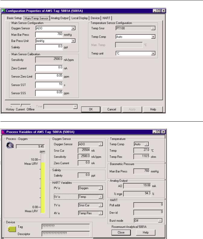
ASSeT MANAGeMeNT SolUTIoNS (AMS)
Rosemount Analytical AMS windows provide access to all transmitter measurement and configuration variables. The user can read raw data, final data, and program settings
and can reconfigure the transmitter from anywhere in the plant. The figures below show two of the many configuration and measurement screens available using HART AMS.
FIGURe 3. AMS configuration screen using HART®
FIGURe 4. AMS measurement screen using HART®
5
 Loading...