


 Loading...
Reference Manual
00809-0100-4697, Rev EA
October 2011
Rosemount 848T High Density Temperature Transmitter with FOUNDATION™ fieldbus
Device Revision 7
www.rosemount.com

Reference Manual
00809-0100-4697, Rev EA
October 2011
Rosemount 848T
Rosemount 848T High Density
Temperature Transmitter with
FOUNDATION fieldbus
NOTICE
Read this manual before working with the product. For personal and system safety, and for optimum product performance, make sure to thoroughly understand the contents before installing, using, or maintaining this product.
The United States has two toll-free assistance numbers and one international number.
Customer Central
1-800-999-9307 (7:00 a.m. to 7:00 p.m. CST)
National Response Center
1-800-654-7768 (24 hours a day) Equipment service needs
International
1-(952) 906-8888
The products described in this document are NOT designed for nuclear-qualified applications.
Using non-nuclear qualified products in applications that require nuclear-qualified hardware or products may cause inaccurate readings.
For information on Rosemount nuclear-qualified products, contact an Emerson Process Management Sales Representative.
www.rosemount.com

Reference Manual
00809-0100-4697, Rev EA
October 2011
Rosemount 848T
Table of Contents
SECTION 1
Introduction
SECTION 2
Installation
SECTION 3
Configuration
Safety Messages . . . . . . . . . . . . . . . . . . . . . . . . . . . . . . . . . . . . . . . . . 1-1
Warnings . . . . . . . . . . . . . . . . . . . . . . . . . . . . . . . . . . . . . . . . . . . . 1-1
Overview . . . . . . . . . . . . . . . . . . . . . . . . . . . . . . . . . . . . . . . . . . . . . . . 1-2
Transmitter . . . . . . . . . . . . . . . . . . . . . . . . . . . . . . . . . . . . . . . . . . . 1-2
Manual . . . . . . . . . . . . . . . . . . . . . . . . . . . . . . . . . . . . . . . . . . . . . . 1-2
Service Support . . . . . . . . . . . . . . . . . . . . . . . . . . . . . . . . . . . . . . . . . . 1-3
Safety Messages . . . . . . . . . . . . . . . . . . . . . . . . . . . . . . . . . . . . . . . . . 2-1
Warnings . . . . . . . . . . . . . . . . . . . . . . . . . . . . . . . . . . . . . . . . . . . . 2-1
Mounting . . . . . . . . . . . . . . . . . . . . . . . . . . . . . . . . . . . . . . . . . . . . . . . 2-1
Mounting to a DIN Rail Without an Enclosure . . . . . . . . . . . . . . . . 2-2
Mounting to a Panel with a Junction Box . . . . . . . . . . . . . . . . . . . . 2-2
Mounting to a 2-in. Pipe Stand . . . . . . . . . . . . . . . . . . . . . . . . . . . . 2-3
Wiring. . . . . . . . . . . . . . . . . . . . . . . . . . . . . . . . . . . . . . . . . . . . . . . . . . 2-4
Connections . . . . . . . . . . . . . . . . . . . . . . . . . . . . . . . . . . . . . . . . . . 2-4
Power Supply . . . . . . . . . . . . . . . . . . . . . . . . . . . . . . . . . . . . . . . . . 2-7
Surges/Transients . . . . . . . . . . . . . . . . . . . . . . . . . . . . . . . . . . . . . 2-7
Grounding . . . . . . . . . . . . . . . . . . . . . . . . . . . . . . . . . . . . . . . . . . . . . . 2-8
Switches . . . . . . . . . . . . . . . . . . . . . . . . . . . . . . . . . . . . . . . . . . . . . . 2-10
Tagging . . . . . . . . . . . . . . . . . . . . . . . . . . . . . . . . . . . . . . . . . . . . . . . 2-11
Installation . . . . . . . . . . . . . . . . . . . . . . . . . . . . . . . . . . . . . . . . . . . . . 2-12
Using Cable Glands . . . . . . . . . . . . . . . . . . . . . . . . . . . . . . . . . . . 2-12
Using Conduit Entries. . . . . . . . . . . . . . . . . . . . . . . . . . . . . . . . . . 2-12
Safety Messages . . . . . . . . . . . . . . . . . . . . . . . . . . . . . . . . . . . . . . . . . 3-1 Warnings . . . . . . . . . . . . . . . . . . . . . . . . . . . . . . . . . . . . . . . . . . . . 3-1 Configuration . . . . . . . . . . . . . . . . . . . . . . . . . . . . . . . . . . . . . . . . . . . . 3-2 Standard . . . . . . . . . . . . . . . . . . . . . . . . . . . . . . . . . . . . . . . . . . . . . 3-2 Transmitter Configuration . . . . . . . . . . . . . . . . . . . . . . . . . . . . . . . . 3-2 Custom Configuration. . . . . . . . . . . . . . . . . . . . . . . . . . . . . . . . . . . 3-2 Methods . . . . . . . . . . . . . . . . . . . . . . . . . . . . . . . . . . . . . . . . . . . . . 3-2 Alarms . . . . . . . . . . . . . . . . . . . . . . . . . . . . . . . . . . . . . . . . . . . . . . 3-3 Damping . . . . . . . . . . . . . . . . . . . . . . . . . . . . . . . . . . . . . . . . . . . . . 3-3 Configure the Differential Sensors . . . . . . . . . . . . . . . . . . . . . . . . . 3-3 Configure Measurement Validation . . . . . . . . . . . . . . . . . . . . . . . . 3-3 Common Configurations for High Density Applications . . . . . . . . . . . . 3-4 Interfacing Analog Transmitters to Foundation fieldbus . . . . . . . . . 3-6 Block Configuration . . . . . . . . . . . . . . . . . . . . . . . . . . . . . . . . . . . . . . . 3-7
Resource Block . . . . . . . . . . . . . . . . . . . . . . . . . . . . . . . . . . . . . . . 3-7 PlantWeb™ Alerts. . . . . . . . . . . . . . . . . . . . . . . . . . . . . . . . . . . . . 3-11
Recommended Actions for PlantWeb Alerts . . . . . . . . . . . . . . . . 3-14 Transducer Blocks . . . . . . . . . . . . . . . . . . . . . . . . . . . . . . . . . . . . 3-15 Transducer Block Sub-Parameter Tables . . . . . . . . . . . . . . . . . . 3-20
TOC-1

Rosemount 848T
Reference Manual
00809-0100-4697, Rev EA
October 2011
SECTION 4
Operation and
Maintenance
APPENDIX A
Reference Data
APPENDIX B
Product Certificates
APPENDIX C Foundation™ fieldbus Technology
APPENDIX D
Function Blocks
Safety Messages . . . . . . . . . . . . . . . . . . . . . . . . . . . . . . . . . . . . . . . . . 4-1 Warnings . . . . . . . . . . . . . . . . . . . . . . . . . . . . . . . . . . . . . . . . . . . . 4-1 Foundation fieldbus Information . . . . . . . . . . . . . . . . . . . . . . . . . . . . . 4-1 Commissioning (Addressing) . . . . . . . . . . . . . . . . . . . . . . . . . . . . . 4-2 Hardware Maintenance . . . . . . . . . . . . . . . . . . . . . . . . . . . . . . . . . . . . 4-3 Sensor Check . . . . . . . . . . . . . . . . . . . . . . . . . . . . . . . . . . . . . . . . . 4-3 Communication/Power Check . . . . . . . . . . . . . . . . . . . . . . . . . . . . 4-3 Resetting the Configuration (RESTART) . . . . . . . . . . . . . . . . . . . . 4-3 Troubleshooting . . . . . . . . . . . . . . . . . . . . . . . . . . . . . . . . . . . . . . . . . . 4-4 Foundation fieldbus . . . . . . . . . . . . . . . . . . . . . . . . . . . . . . . . . . . . 4-4 Resource Block . . . . . . . . . . . . . . . . . . . . . . . . . . . . . . . . . . . . . . . 4-4 Transducer Block Troubleshooting. . . . . . . . . . . . . . . . . . . . . . . . . 4-4
Functional Specifications . . . . . . . . . . . . . . . . . . . . . . . . . . . . . . . . . . . A-1
Physical Specifications . . . . . . . . . . . . . . . . . . . . . . . . . . . . . . . . . . . . A-3
Function Blocks . . . . . . . . . . . . . . . . . . . . . . . . . . . . . . . . . . . . . . . . . . A-4
Performance Specifications . . . . . . . . . . . . . . . . . . . . . . . . . . . . . . . . . A-4
Dimensional Drawings . . . . . . . . . . . . . . . . . . . . . . . . . . . . . . . . . . . . . A-8
Mounting Options . . . . . . . . . . . . . . . . . . . . . . . . . . . . . . . . . . . . . A-11
Ordering Information . . . . . . . . . . . . . . . . . . . . . . . . . . . . . . . . . . . . . A-12
Hazardous Locations Certificates . . . . . . . . . . . . . . . . . . . . . . . . . . . . B-1
North American Approvals . . . . . . . . . . . . . . . . . . . . . . . . . . . . . . . B-1
European Approvals . . . . . . . . . . . . . . . . . . . . . . . . . . . . . . . . . . . . B-4
Intrinsically Safe and Non-Incendive Installations . . . . . . . . . . . . . . . B-11
Installation Drawings . . . . . . . . . . . . . . . . . . . . . . . . . . . . . . . . . . . . . B-12
Overview . . . . . . . . . . . . . . . . . . . . . . . . . . . . . . . . . . . . . . . . . . . . . . .C-1
Function Blocks . . . . . . . . . . . . . . . . . . . . . . . . . . . . . . . . . . . . . . . . . .C-1
Device Descriptions . . . . . . . . . . . . . . . . . . . . . . . . . . . . . . . . . . . . . . .C-3
Block Operation . . . . . . . . . . . . . . . . . . . . . . . . . . . . . . . . . . . . . . . . . .C-3
InstrumentSpecific Function Blocks . . . . . . . . . . . . . . . . . . . . . . .C-3
Alerts . . . . . . . . . . . . . . . . . . . . . . . . . . . . . . . . . . . . . . . . . . . . . . .C-3
Network Communication . . . . . . . . . . . . . . . . . . . . . . . . . . . . . . . . . . .C-4
Link Active Scheduler (LAS). . . . . . . . . . . . . . . . . . . . . . . . . . . . . .C-4
Addressing . . . . . . . . . . . . . . . . . . . . . . . . . . . . . . . . . . . . . . . . . . .C-6
Scheduled Transfers . . . . . . . . . . . . . . . . . . . . . . . . . . . . . . . . . . .C-6
Unscheduled Transfers . . . . . . . . . . . . . . . . . . . . . . . . . . . . . . . . .C-7
Function Block Scheduling . . . . . . . . . . . . . . . . . . . . . . . . . . . . . . .C-8
Analog Input (AI) Function Block . . . . . . . . . . . . . . . . . . . . . . . . . . . . .D-1
Functionality . . . . . . . . . . . . . . . . . . . . . . . . . . . . . . . . . . . . . . . . . .D-3
AI Block Troubleshooting . . . . . . . . . . . . . . . . . . . . . . . . . . . . . . . .D-8
Multiple Analog Input (MAI) Function Block. . . . . . . . . . . . . . . . . . . . .D-9
Functionality . . . . . . . . . . . . . . . . . . . . . . . . . . . . . . . . . . . . . . . . .D-10
MAI Block Troubleshooting. . . . . . . . . . . . . . . . . . . . . . . . . . . . . .D-14
Input Selector Function Block . . . . . . . . . . . . . . . . . . . . . . . . . . . . . .D-15
Functionality . . . . . . . . . . . . . . . . . . . . . . . . . . . . . . . . . . . . . . . . .D-17
ISEL Block Troubleshooting . . . . . . . . . . . . . . . . . . . . . . . . . . . . .D-20
TOC-2

Reference Manual
00809-0100-4697, Rev EA
October 2011
Rosemount 848T
Section 1 |
Introduction |
SAFETY MESSAGES
Warnings
Safety Messages . . . . . . . . . . . . . . . . . . . . . . . . . . . . . . . . . page 1-1 Overview . . . . . . . . . . . . . . . . . . . . . . . . . . . . . . . . . . . . . . . page 1-2 Service Support . . . . . . . . . . . . . . . . . . . . . . . . . . . . . . . . . page 1-3
Instructions and procedures in this section may require special precautions to ensure the safety of the personnel performing the operations. Information that potentially raises safety issues is indicated by a warning symbol ( ). Please refer to the following safety messages before performing an operation preceded by this symbol.
Failure to follow these installation guidelines could result in death or serious injury.
•Make sure only qualified personnel perform the installation.
Process leaks could result in death or serious injury.
•Do not remove the thermowell while in operation. Removing while in operation may cause process fluid leaks.
•Install and tighten thermowells and sensors before applying pressure, or process leakage may result.
Electrical shock could cause death or serious injury.
•If the sensor is installed in a high voltage environment and a fault condition or installation error occurs, high voltage may be present on transmitter leads and terminals.
•Use extreme caution when making contact with the leads and terminals.
www.rosemount.com

Rosemount 848T
Reference Manual
00809-0100-4697, Rev EA
October 2011
OVERVIEW
Transmitter |
The Rosemount 848T is optimal for process temperature measurement |
|
because of its ability to simultaneously measure eight separate and |
|
independent temperature points with one transmitter. Multiple temperature |
|
sensor types may be connected to each 848T transmitter. In addition, the |
|
848T can accept 4-20 mA inputs. The enhanced measurement capability of |
|
the 848T allows it to communicate these variables to any FOUNDATION |
|
fieldbus host or configuration tool. |
Manual |
This manual is designed to assist in the installation, operation, and |
|
maintenance of the Rosemount 848T Temperature Transmitter. |
Section 1: Introduction
•Overview
•Considerations
•Return of Materials
Section 2: Installation
•Mounting
•Installation
•Wiring
•Power Supply
•Commissioning
Section 3: Configuration
•FOUNDATION fieldbus Technology
•Configuration
•Function Block Configuration
Section 4: Operation and Maintenance
•Hardware Maintenance
•Troubleshooting
Appendix A: Specification and Reference Data
•Specifications
•Dimensional Drawings
•Ordering Information
Appendix B: Product Certificates
•Hazardous Locations Certificates
•Intrinsically Safe and Non-Incendive Installations
•Installation Drawings
Appendix C: Foundation™ Fieldbus Technology
•Device Descriptions
•Block Operation
Appendix D: Function Blocks
•Analog Input (AI) Function Block
•Multiple Analog Input (MAI) Function Block
•Input Selector Function Block
1-2

Reference Manual
00809-0100-4697, Rev EA
October 2011
Rosemount 848T
SERVICE SUPPORT
To expedite the return process in North America, call the Emerson Process Management National Response Center toll-free at 800-654-7768. This center, available 24 hours a day, will assist with any needed information or materials.
 The center will ask for the following information:
•Product model
•Serial numbers
•The last process material to which the product was exposed
The center will provide
•A Return Material Authorization (RMA) number
•Instructions and procedures that are necessary to return goods that were exposed to hazardous substances
For other locations, please contact an Emerson Process Management sales representative.
NOTE
If a hazardous substance is identified, a Material Safety Data Sheet (MSDS), required by law to be available to people exposed to specific hazardous substances, must be included with the returned materials.
1-3

Rosemount 848T
Reference Manual
00809-0100-4697, Rev EA
October 2011
1-4
Reference Manual
00809-0100-4697, Rev EA
October 2011
Rosemount 848T
Section 2 |
Installation |
SAFETY MESSAGES
Warnings
MOUNTING
Safety Messages . . . . . . . . . . . . . . . . . . . . . . . . . . . . . . . . . page 2-1 Mounting . . . . . . . . . . . . . . . . . . . . . . . . . . . . . . . . . . . . . . . page 2-1 Wiring . . . . . . . . . . . . . . . . . . . . . . . . . . . . . . . . . . . . . . . . . . page 2-4 Grounding . . . . . . . . . . . . . . . . . . . . . . . . . . . . . . . . . . . . . . page 2-8 Switches . . . . . . . . . . . . . . . . . . . . . . . . . . . . . . . . . . . . . . . page 2-10 Tagging . . . . . . . . . . . . . . . . . . . . . . . . . . . . . . . . . . . . . . . . page 2-11 Installation . . . . . . . . . . . . . . . . . . . . . . . . . . . . . . . . . . . . . . page 2-12
Instructions and procedures in this section may require special precautions to ensure the safety of the personnel performing the operations. Information that potentially raises safety issues is indicated by a warning symbol ( ). Please refer to the following safety messages before performing an operation preceded by this symbol.
Failure to follow these installation guidelines could result in death or serious injury.
•Make sure only qualified personnel perform the installation.
Process leaks could result in death or serious injury.
•Do not remove the thermowell while in operation. Removing while in operation may cause process fluid leaks.
•Install and tighten thermowells and sensors before applying pressure, or process leakage may result.
Electrical shock could cause death or serious injury.
•If the sensor is installed in a high voltage environment and a fault condition or installation error occurs, high voltage may be present on transmitter leads and terminals.
•Use extreme caution when making contact with the leads and terminals.
The 848T is always mounted remote from the sensor assembly. There are three mounting configurations:
•To a DIN rail without an enclosure
•To a panel with an enclosure
•To a 2-in pipe stand with an enclosure using a pipe mounting kit
www.rosemount.com
Rosemount 848T
Reference Manual
00809-0100-4697, Rev EA
October 2011
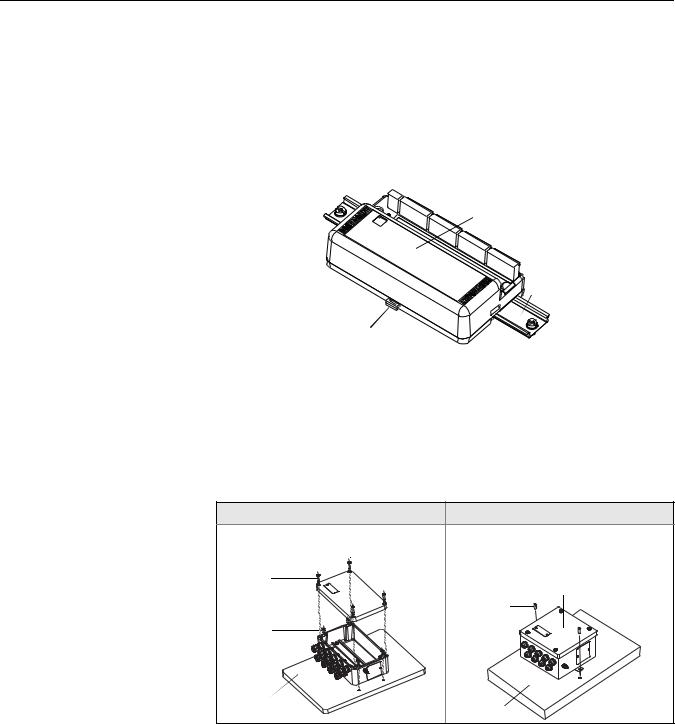
Mounting to a DIN Rail Without an Enclosure
Figure 2-1. Mounting the 848T to a DIN Rail
To mount the 848T to a DIN rail without an enclosure, follow these steps:
1.Pull up the DIN rail mounting clip located on the top back side of the transmitter.
2.Hinge the DIN rail into the slots on the bottom of the transmitter.
3.Tilt the 848T and place onto the DIN rail. Release the mounting clip. The transmitter should be securely fastened to the DIN rail.
848T without  installed
enclosure
DIN Rail
DIN Rail Mounting Clip
Mounting to a Panel with a Junction Box
Figure 2-2. Mounting the 848T junction box to a panel
When inside of a plastic or aluminum junction box, the 848T mounts to a panel using four 1/4-20 x 1.25-in. screws.
When inside of a stainless steel junction box, the 848T mounts to a panel using two 1/4-20 x 1/2-in. screws.
Aluminum/Plastic |
Stainless Steel |
848T with aluminum or plastic box |
|
Cover |
|
Screws (4) |
848T with a stainless steel box |
|
Mounting |
Mounting |
Screws (2) |
|
|
Screws (4) |
|
Panel |
Panel |
|
2-2
Reference Manual
00809-0100-4697, Rev EA
October 2011
Rosemount 848T
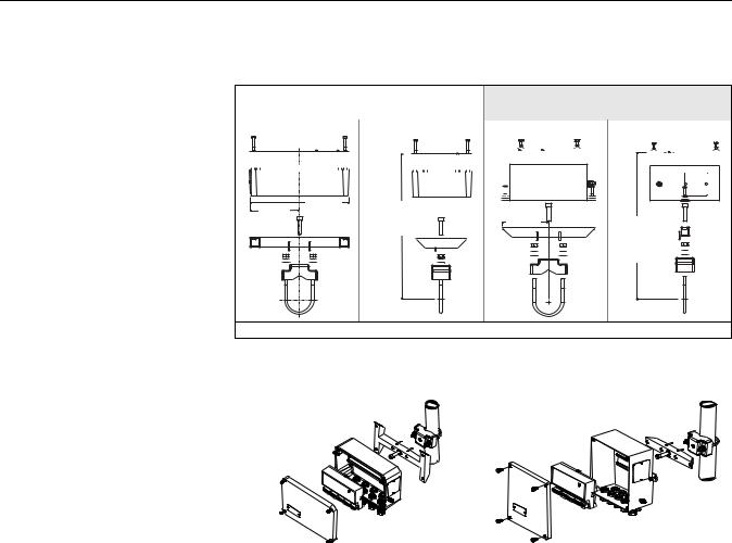
Mounting to a 2-in. Pipe Stand
Use the optional mounting bracket (option code B6) to mount the 848T to a 2-in. pipe stand when using a junction box.
|
|
|
|
Aluminum/Plastic Junction Box |
|
|
|
|
|
Stainless Steel Junction Box |
|||||||||||||||||||||||||||||
|
|
|
|
|
|
(styles JA and JP) |
|
|
|
|
|
|
|
(style JS) |
|||||||||||||||||||||||||
|
|
|
|
Front View |
Side View |
|
|
|
Front View |
|
|
|
Side View |
||||||||||||||||||||||||||
|
|
|
|
|
|
|
|
|
|
|
|
|
|
|
|
|
|
|
|
|
|
|
|
|
|
|
|
|
|
|
|
|
|
|
|
|
|
|
|
|
|
|
|
|
|
|
|
|
|
|
|
|
|
|
|
|
|
|
|
|
|
|
|
|
|
|
|
|
|
|
|
|
|
|
|
|
|
|
|
|
|
|
|
|
|
|
|
|
|
|
|
|
|
|
|
|
|
|
|
|
|
|
|
|
|
|
|
|
|
|
|
|
|
|
|
|
|
|
|
|
|
|
|
|
|
|
|
|
|
|
|
|
|
|
|
|
|
|
|
|
|
|
|
|
|
|
|
|
|
|
|
|
|
|
|
|
|
|
|
5.1 |
10.2 |
6.6 (167) |
4.7 |
|
(260) |
fully |
(119) |
7.5 (190) |
|
(130) |
|
assembled |
||
|
|
|
fully |
|
|
|
|
|
assembled |
Dimensions are in inches (millimeters)
Aluminum/Plastic Junction Box |
Stainless Steel Junction Box |
Mounted on a Vertical Pipe |
Mounted on a Vertical Pipe |
|
|
2-3
Rosemount 848T
Reference Manual
00809-0100-4697, Rev EA
October 2011
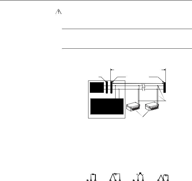
WIRING
Figure 2-3. 848T Transmitter
Field Wiring
If the sensor is installed in a high-voltage environment and a fault condition or installation error occurs, the sensor leads and transmitter terminals could carry lethal voltages. Use extreme caution when making contact with the leads and terminals.
NOTE
Do not apply high voltage (e.g. AC line voltage) to the transmitter terminals. Abnormally high voltage can damage the unit (bus terminals are rated to 42.4 VDC).
|
6234 ft (1900 m) max |
|
||
|
(depending upon cable |
|
||
Integrated Power |
characteristics) |
|
|
|
Conditioner |
Terminators |
|
|
|
and Filter |
|
|
||
|
(Trunk) |
|
|
|
Power |
|
|
|
|
Supply |
(Spur) |
(Spur) |
|
|
FOUNDATION |
Signal |
|||
|
|
|||
fieldbus Host or |
|
|
Wiring |
|
configuration tool |
|
|
|
|
|
Devices 1 through 16* |
|||
|
* Intrinsically safe installations may allow fewer devices per I.S. barrier |
|
|
|
|||||||
Connections |
The 848T transmitter is compatible with 2 or 3-wire RTD, thermocouple, Ohm, |
||||||||||
|
and millivolt sensor types. Figure 2-4 shows the correct input connections to |
||||||||||
|
the sensor terminals on the transmitter. The 848T can also accept inputs from |
||||||||||
|
analog devices using the optional analog input connector. Figure 2-5 shows |
||||||||||
|
the correct input connections to the analog input connector when installed on |
||||||||||
|
the transmitter. Tighten the terminal screws to ensure proper connection. |
||||||||||
Figure 2-4. Sensor Wiring |
|
|
|
|
|
|
|
|
|
|
|
Diagram |
|
|
|
|
|
|
|
|
|
|
|
|
1 2 |
3 |
1 |
2 |
3 |
1 |
2 |
3 |
1 |
2 |
3 |
|
2-wire |
3-wire |
Thermocouples / |
2-Wire RTD |
|||||||
|
RTD and |
RTD and |
Ohms and |
|
with |
||||||
|
Ohms |
Ohms* |
Millivolts |
Compensation |
|||||||
|
|
|
|
|
|
|
|
|
Loop** |
||
*Emerson Process Management provides 4-wire sensors for all single-element RTDs. Use these RTDs in 3-wire configurations by clipping the fourth lead or leaving it disconnected and insulated with electrical tape.
**The transmitter must be configured for a 3-wire RTD in order to recognize an RTD with a compensation loop.
2-4

Reference Manual
00809-0100-4697, Rev EA
October 2011
Rosemount 848T
RTD or Ohm Inputs
Various RTD configurations, including 2-wire and 3-wire are used in industrial applications. If the transmitter is mounted remotely from a 3-wire RTD, it will operate within specifications, without recalibration, for lead wire resistances of up to 60 ohms per lead (equivalent to 6,000 feet of 20 AWG wire). If using a 2-wire RTD, both RTD leads are in series with the sensor element, so errors can occur if the lead lengths exceed one foot of 20 AWG wire. Compensation for this error is provided when using 3-wire RTDs.
Thermocouple or Millivolt Inputs
Use appropriate thermocouple extension wire to connect the thermocouple to the transmitter. Make connections for millivolt inputs using copper wire. Use shielding for long runs of wire.
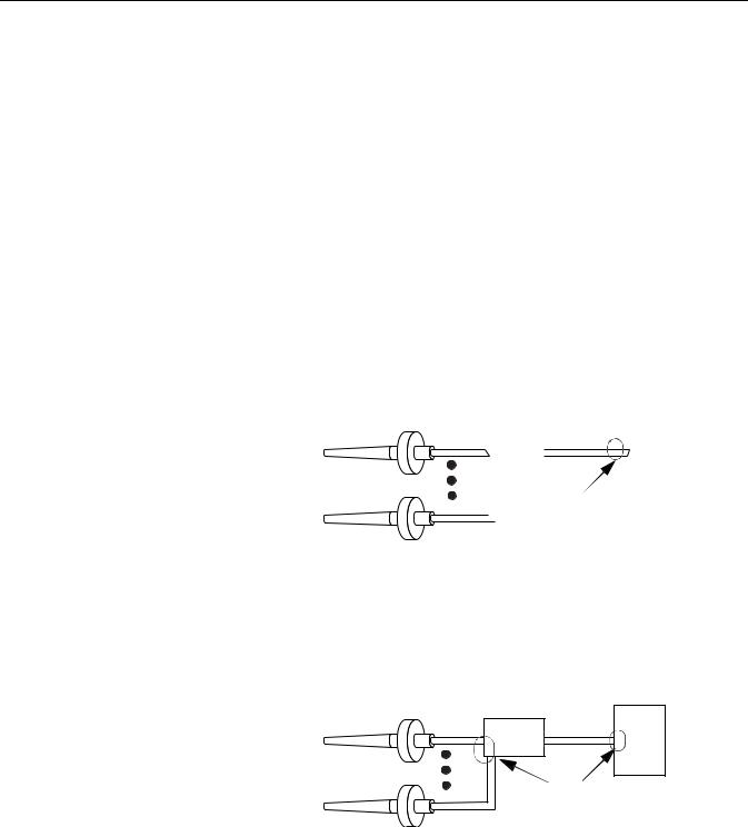
Analog Inputs
The analog connector converts the 4–20 mA signal to a 20–100 mV signal that can be read by the 848T and transmitted using FOUNDATION fieldbus.
Use the following steps when installing the 848T with the analog connector:
1.The 848T, when ordered with option code S002, comes with four analog connectors. Replace the standard connector with the analog connector on the desired channels.
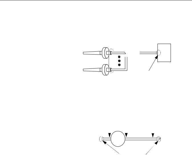
2.Wire one or two analog transmitters to the analog connector according to Figure 2-5. There is space available on the analog connector label for identification of the analog inputs.
NOTE
Power supply should be rated to support the connected transmitter(s).
3.If the analog transmitters can communicate using HART protocol, the analog connectors are supplied with the ability to switch in a 250 ohm resistor for HART communication (see Figure 2-6).
One switch is supplied for each input (top switch for “A” inputs and bottom switch for “B” inputs). Setting the switch in the “ON” position (to the right) bypasses the 250 ohm resistor. Terminals are provided for each analog input to connect a Field Communicator for local configuration.
2-5

Rosemount 848T
Reference Manual
00809-0100-4697, Rev EA
October 2011
Figure 2-5. 848T Analog Input
Wiring Diagram
Figure 2-6. 848T Analog
Connector
Analog Input |
Connectors |
Analog Transmitters |
Power Supply |
250 ohm resistor in the loop when switched to the left
HART |
HART |
Channel A |
Channel B |
Space available for identification of inputs
2-6

Reference Manual
00809-0100-4697, Rev EA
October 2011
Rosemount 848T
Power Supply |
Connections |
||||||||||||||||||||||||||
|
The transmitter requires between 9 and 32 VDC to operate and provide |
||||||||||||||||||||||||||
|
complete functionality. The DC power supply should provide power with less |
||||||||||||||||||||||||||
|
than 2% ripple. A fieldbus segment requires a power conditioner to isolate the |
||||||||||||||||||||||||||
|
power supply filter and decouple the segment from other segments attached |
||||||||||||||||||||||||||
|
to the same power supply. |
||||||||||||||||||||||||||
|
All power to the transmitter is supplied over the signal wiring. Signal wiring |
||||||||||||||||||||||||||
|
should be shielded, twisted pair for best results in electrically noisy |
||||||||||||||||||||||||||
|
environments. Do not use unshielded signal wiring in open trays with power |
||||||||||||||||||||||||||
|
wiring or near heavy electrical equipment. |
||||||||||||||||||||||||||
|
Use ordinary copper wire of sufficient size to ensure that the voltage across the |
||||||||||||||||||||||||||
|
transmitter power terminals does not go below 9 VDC. The power terminals are |
||||||||||||||||||||||||||
|
polarity insensitive. To power the transmitter: |
||||||||||||||||||||||||||
|
1. |
|
|
|
|
Connect the power leads to the terminals marked “Bus,” as shown in |
|||||||||||||||||||||
|
|
|
|
|
|
|
|
Figure 2-7. |
|||||||||||||||||||
|
2. |
|
|
|
|
Tighten the terminal screws to ensure adequate contact. No |
|||||||||||||||||||||
|
|
|
|
|
|
|
|
additional power wiring is necessary. |
|||||||||||||||||||
Figure 2-7. Transmitter Label |
|
|
|
|
|
|
|
|
|
|
|
|
|
|
|
|
|
|
|
|
|
|
|
|
|
|
|
|
|
|
|
|
|
|
|
|
|
|
|
|
|
|
|
|
|
|
|
|
|
|
|
|
|
|
NOT USED |
|
|
|
|
|
|
|
|
|
|
|
|
|
|
|
|
|
|
|
|
|
|
|
|
|
|
|
|
|
|
|
|
|
|
|
|
|
|
|
|
|
|
|
|
|
|
|
|
|
|
|
|
|
|
|
|
|
|
|
|
|
|
|
|
|
|
|
|
|
|
|
|
|
|
|
|
|
|
|
|
|
|
|
|
|
|
|
|
|
|
|
|
|
|
|
|
|
|
|
|
|
|
|
|
|
|
|
|
|
|
|
|
|
|
|
|
|
|
|
|
|
|
|
|
|
|
|
|
|
|
|
|
|
|
|
|
|
|
|
|
|
|
|
|
|
|
|
|
|
|
|
|
|
|
|
|
|
|
|
|
|
|
|
|
|
|
|
SECURITY |
|
|
|
|
|
|
|
|
|
|
|
|
|
|
|
|
|
|
|
|
|
|
|
|
|
|
|
|
|
|
|
|
|
|
|
|
|
|
|
|
|
|
|
|
|
|
|
|
|
|
|
|
|
|
|
SIMULATE ENABLE |
|
|
|
|
|
|
|
|
|
|
|
|
|
|
|
|
|
|
|
|
|
|
|
|
|
|
|
|
|
|
|
|
|
|
|
|
|
|
|
|
|
|
|
|
|
|
|
|
|
|
|
|
|
|
|
|
|
|
|
|
|
|
|
|
|
|
|
|
|
|
|
|
|
|
|
|
|
|
|
|
|
|
|
|
|
|
|
|
|
|
|
|
|
|
|
|
|
|
|
|
|
|
|
|
|
|
|
|
|
|
|
|
|
|
|
|
|
|
|
|
|
|
|
|
|
|
|
|
|
|
|
|
|
|
|
|
|
|
|
|
|
|
|
|
|
|
|
|
|
|
|
|
|
|
|
|
|
|
|
|
|
|
|
|
|
|
|
|
|
|
|
|
|
|
|
|
|
|
|
|
|
|
|
|
|
|
|
|
|
|
|
|
|
|
|
|
|
|
|
|
|
|
|
|
|
|
|
|
|
|
|
|
|
|
|
|
|
|
|
|
|
|
|
|
|
|
|
|
|
|
|
|
|
|
|
|
|
|
|
|
|
|
|
|
|
|
|
|
|
|
|
|
|
Ground |
|
(required with T1 option) |
|
Connect Power Leads Here |
Surges/Transients |
The transmitter will withstand electrical transients encountered through static |
|
discharges or induced switching transients. However, a transient protection |
|
option (option code T1) is available to protect the 848T against high-energy |
|
transients. The device must be properly grounded using the ground terminal |
|
(see Figure 2-7). |
2-7
Rosemount 848T
Reference Manual
00809-0100-4697, Rev EA
October 2011
GROUNDING |
The 848T transmitter provides input/output isolation up to 620 V rms. |
||||||||
|
|
|
|
|
|
|
|
|
|
|
NOTE |
|
|
|
|
|
|
|
|
|
Neither conductor of the fieldbus segment can be grounded. Grounding out |
||||||||
|
one of the signal wires will shut down the entire fieldbus segment. |
||||||||
|
|
|
|
|
|
|
|
|
|
|
Shielded Wire |
|
|
||||||
|
Each process installation has different requirements for grounding. Use the |
||||||||
|
grounding options recommended by the facility for the specific sensor type or |
||||||||
|
begin with grounding option 1 (most common). |
|
|
||||||
|
Ungrounded Thermocouple, mV, and RTD/Ohm Inputs |
|
|
||||||
|
Option 1: |
|
|
||||||
|
1. |
Connect signal wiring shield to the sensor wiring shield(s). |
|||||||
|
2. |
Ensure the shields are tied together and electrically isolated from the |
|||||||
|
|
transmitter enclosure. |
|
|
|||||
|
3. |
Only ground shield at the power supply end. |
|
|
|||||
|
4. |
Ensure that the sensor shield(s) is electrically isolated from the |
|||||||
|
|
surrounding grounded fixtures. |
|
|
|||||
|
|
|
|
|
|
|
|
|
|
|
|
|
|
|
|
|
|
Power |
|
|
|
|
|
|
848T |
|
|
||
|
|
|
|
|
|
|
Supply |
|
|
|
|
|
|
|
|
|
|
||
|
|
|
|
|
|
|
|
|
|
|
|
|
|
|
|
|
|
|
|
|
|
Sensor Wires |
|
|
|
|
|
|
|
|
|
|
|
|
Shield ground point |
||||
|
|
|
|
|
|
|
|
|
|
|
|
|
|
|
|
|
|
|
|
Option 2:
1.Connect sensor wiring shield(s) to the transmitter enclosure (only if the enclosure is grounded).
2.Ensure the sensor shield(s) is electrically isolated from surrounding fixtures that may be grounded.
3.Ground signal wiring shield at the power supply end.
848T |
Power |
Supply |
|
Sensor Wires |
|
|
Shield ground points |
2-8
Reference Manual
00809-0100-4697, Rev EA
October 2011
Rosemount 848T
Grounded Thermocouple Inputs
1.Ground sensor wiring shield(s) at the sensor.
2.Ensure that the sensor wiring and signal wiring shields are electrically isolated from the transmitter enclosure.
3.Do not connect the signal wiring shield to the sensor wiring shield(s).
4.Ground signal wiring shield at the power supply end.
|
|
Power |
|
848T |
|||
|
Supply |
||
|
|||
|
|
|
|
|
|
|
Sensor Wires

 Shield ground points
Analog Device Inputs
1.Ground analog signal wire at the power supply of the analog devices.
2.Ensure that the analog signal wire and the fieldbus signal wire shields are electrically isolated from the transmitter enclosure.
3.Do not connect the analog signal wire shield to the fieldbus signal wire shield.
4.Ground fieldbus signal wire shield at the power supply end.
|
|
4-20 mA loop |
|
FOUNDATION |
||||
|
|
|
fieldbus bus |
|||||
|
|
|
|
|
|
|
|
|
|
|
|
|
|
|
|
|
Power |
AnalogDevice |
|
Analog |
|
|
|
|
||
|
848T |
|
|
|
Supply |
|||
Power Supply |
|
|
|
|
||||
|
|
Device |
|
|
|
|
|
|
|
|
|
|
|
|
|
|
|
|
|
|
|
|
|
|
|
|
Shield ground points
Transmitter Enclosure (optional)
Ground the transmitter in accordance with local electrical requirements.
2-9

Rosemount 848T
Reference Manual
00809-0100-4697, Rev EA
October 2011
SWITCHES
Figure 2-8. Switch Location on the Rosemount 848T
NOT USED
SECURITY
SIMULATE ENABLE
Security
After configuring the transmitter, the data can be protected from unwarranted changes. Each 848T is equipped with a security switch that can be positioned “ON” to prevent the accidental or deliberate change of configuration data.
This switch is located on the front side of the electronics module and is labeled SECURITY.
See Figure 2-8 for switch location on the transmitter label.
Simulate Enable
The switch labeled SIMULATE ENABLE is used in conjunction with the Analog Input (AI) and Multiple Analog Input (MAI) function blocks. This switch is used to simulate temperature measurement.
Not Used
The switch is not functional.
2-10
Reference Manual
00809-0100-4697, Rev EA
October 2011
Rosemount 848T
TAGGING |
Commissioning Tag |
|
The 848T has been supplied with a removable commissioning tag that |
|
contains both the Device ID (the unique code that identifies a particular device |
|
in the absence of a device tag) and a space to record the device tag (the |
|
operational identification for the device as defined by the Piping and |
|
Instrumentation Diagram (P&ID)). |
|
When commissioning more than one device on a fieldbus segment, it can be |
|
difficult to identify which device is at a particular location. The removable tag, |
|
provided with the transmitter, can aid in this process by linking the Device ID |
|
to its physical location. The installer should note the physical location of the |
|
transmitter on both the upper and lower location of the commissioning tag. |
|
The bottom portion should be torn off for each device on the segment and |
|
used for commissioning the segment in the control system. |
Figure 2-9. Commissioning Tag |
|
Device ID


Device Tag


 to denote
  physical

location
Transmitter Tag
Hardware
•Tagged in accordance with customer requirements
•Permanently attached to the transmitter
Software
•The transmitter can store up to 32 characters
•If no characters are specified, the first 30 characters of the hardware tag will be used
Sensor Tag
Hardware
•A plastic tag is provided to record identification of eight sensors
•This information can be printed at the factory upon request
•In the field, the tag can be removed, printed onto, and reattached to the transmitter
Software
•If sensor tagging is requested, the Transducer Block SERIAL_NUMBER parameters will be set at the factory
•The SERIAL_NUMBER parameters can be updated in the field
2-11
Rosemount 848T
Reference Manual
00809-0100-4697, Rev EA
October 2011
INSTALLATION
Using Cable Glands
Figure 2-10. Installing the 848T with Cable Glands
Using Conduit Entries
Figure 2-11. Installing the 848T with Conduit Entries
Use the following steps to install the 848T with Cable Glands:
1.Remove the junction box cover by unscrewing the four cover screws.
2.Run the sensor and power/signal wires through the appropriate cable glands using the pre-installed cable glands (see Figure 2-10).
3.Install the sensor wires into the correct screw terminals (follow the label on the electronics module).
4.Install the power/signal wires onto the correct screw terminals. Power is polarity insensitive, allowing the user to connect positive (+) or negative (–) to either Fieldbus wiring terminal labeled “Bus.”
5.Replace the enclosure cover and securely tighten all cover screws.
Enclosure Cover |
Sensor 7 |
|
Sensor 5 |
||
Screw (4) |
||
Sensor 3 |
||
|
||
|
Sensor 1 |


 Power/Signal
|
Sensor 8 |
Cable Gland |
Sensor 6 |
Sensor 4 |
|
|
Sensor 2 |
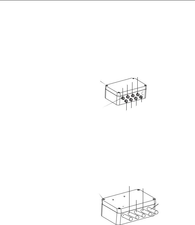
Use the following steps to install the 848T with Conduit Entries:
1.Remove the junction box cover by unscrewing the four cover screws.
2.Remove the five conduit plugs and install five conduit fittings (supplied by the installer).
3.Run pairs of sensor wires through each conduit fitting.
4.Install the sensor wires into the correct screw terminals (follow the label on the electronics module).
5.Install the power/signal wires into the correct screw terminals. Power is polarity insensitive, allowing the user to connect positive (+) or negative (–) to either Fieldbus wiring terminal labeled “Bus.”
6.Replace the junction box cover and securely tighten all cover screws.
|
Sensor 3 and 4 Conduit |
Sensor 7 and 8 Conduit |
|
|
|
|
|
Enclosure |
|
Sensor |
|
Cover Screw |
Sensors |
5 and 6 |
|
|
Conduit |
||
|
1 and 2 |
|
Power/Signal |
|
Conduit |
|
|
|
|
Conduit |
|
|
|
|
|
2-12

Reference Manual
00809-0100-4697, Rev EA
October 2011
Rosemount 848T
Section 3 |
Configuration |
SAFETY MESSAGES
Warnings
Safety Messages . . . . . . . . . . . . . . . . . . . . . . . . . . . . . . . . . page 3-1 Configuration . . . . . . . . . . . . . . . . . . . . . . . . . . . . . . . . . . . page 3-2 Common Configurations for High Density Applications page 3-4 Block Configuration . . . . . . . . . . . . . . . . . . . . . . . . . . . . . . page 3-7
Instructions and procedures in this section may require special precautions to ensure the safety of the personnel performing the operations. Information that potentially raises safety issues is indicated by a warning symbol ( ). Please refer to the following safety messages before performing an operation preceded by this symbol.
Failure to follow these installation guidelines could result in death or serious injury.
•Make sure only qualified personnel perform the installation.
Process leaks could result in death or serious injury.
•Do not remove the thermowell while in operation. Removing while in operation may cause process fluid leaks.
•Install and tighten thermowells and sensors before applying pressure, or process leakage may result.
Electrical shock could cause death or serious injury.
•If the sensor is installed in a high voltage environment and a fault condition or installation error occurs, high voltage may be present on transmitter leads and terminals.
•Use extreme caution when making contact with the leads and terminals.
www.rosemount.com

Rosemount 848T
Reference Manual
00809-0100-4697, Rev EA
October 2011
CONFIGURATION
Standard |
Each FOUNDATION fieldbus configuration tool or host system has a different |
|
way of displaying and performing configurations. Some will use Device |
|
Descriptions (DDs) and DD Methods to make configuration and displaying of |
|
data consistent across host platforms. |
|
Unless otherwise specified, the 848T will be shipped with the following |
|
configuration (default): |
Table 3-1. Standard
Configuration Settings
Transmitter
Configuration
Custom Configuration
Methods
Sensor Type(1) |
Type J Thermocouple |
|
Damping(1) |
5 seconds |
|
Measurement Units(1) |
°C |
|
Output(1) |
Linear with Temperature |
|
Line Voltage Filter(1) |
60 Hz |
|
Temperature Specific Blocks |
• |
Transducer Block (1) |
|
|
|
FOUNDATION fieldbus Function Blocks |
• |
Analog Input (8) |
|
• |
Multiple Analog Input (2) |
|
• |
Input Selector (4) |
|
|
|
(1) For all eight sensors
Refer to that systems documentation to perform configuration changes using a FOUNDATION fieldbus host or configuration tool.
NOTE
To make configuration changes, ensure that the block is Out of Service (OOS) by setting the MODE_BLK.TARGET to OOS, or set the SENSOR_MODE to Configuration.
The transmitter is available with the standard configuration setting. The configuration settings and block configuration may be changed in the field with the Emerson Process Management Systems DeltaV®, with AMSinside, or other FOUNDATION fieldbus host or configuration tool.
Custom configurations are to be specified when ordering.
For FOUNDATION fieldbus hosts or configuration tools that support device description (DD) methods, there are two configuration methods available in the Transducer block. These methods are included with the DD software.
•Sensor Configuration
•Sensor Input Trim (user input trim)
See the host system documentation for information on running DD methods from the host system. If the FOUNDATION fieldbus host or configuration tool does not support DD methods, refer to “Block Configuration” on page 3-7 for information on how to modify sensor configuration parameters.
3-2

Reference Manual
00809-0100-4697, Rev EA
October 2011
Rosemount 848T
Alarms
Damping
Configure the Differential
Sensors
Configure Measurement
Validation
Use the following steps to configure the alarms, which are located in the Resource Function Block.
1.Set the resource block to OOS.
2.Set WRITE_PRI to the appropriate alarm level (WRITE_PRI has a selectable range of priorities from 0 to 15, see “Alarm Priority Levels” on page 3-11. Set the other block alarm parameters at this time.
3.Set CONFIRM_TIME to the time, in 1/32 of a millisecond, that the device will wait for confirmation of receiving a report before trying again (the device does not retry if CONFIRM_TIME is 0).
4.Set LIM_NOTIFY to a value between zero and MAX_NOTIFY. LIM_NOTIFY is the maximum number of alert reports allowed before the operator needs to acknowledge an alarm condition.
5.Enable the reports bit in FEATURES_SEL. (When Multi-bit alerts is enabled, every active alarm is visible for any of the eight sensors, generated by a PlantWeb alert. This is different than only viewing the highest priority alarm.)
6.Set the resource block to AUTO.
For modifying alarms on individual function blocks (AI or ISEL blocks), refer to Appendix D: Function Blocks.
Use the following steps to configure the damping, which is located in the Transducer Function Block.
1.Set Sensor Mode to Out of Service.
2.Change DAMPING to the desired filter rate (0.0 to 32.0 seconds).
3.Set Sensor Mode to In Service.
Use the following steps to configure the Differential Sensors:
1.Set Dual Sensor Mode to Out of Service.
2.Set Input A and Input B to the sensor values that are to be used in the differential equation diff = A–B. (NOTE: Unit types must be the same.)
3.Set the DUAL_SENSOR_CALC to either Not Used, Absolute, or INPUT A minus INPUT B.
4.Set Dual Sensor Mode to In Service.
Use the following steps to configure Measurement Validation:
1.Set mode to Disabled for specific sensor.
2.Select sample rate. 1-10 sec/sample is available. 1 second/sample is preferred for sensor degradation. The higher the number of seconds between samples, the more emphasis put on process variation.
3.Select Deviation Limit from 0 to 10 units. If deviation limit is exceeded, a status event will be triggered.
4.Select Increasing Limit. Sets the limit for increasing rate of change. If limit is exceeded, a status event will be triggered.
5.Select Decreasing Limit. Sets the limit for decreasing rate of change. If limit is exceeded, a status event will be triggered.
NOTE:
The decreasing limit selected is required to be a negative value.
3-3

Rosemount 848T
Reference Manual
00809-0100-4697, Rev EA
October 2011
COMMON CONFIGURATIONS FOR HIGH DENSITY APPLICATIONS

 Out_1
Out_1

 Out_2
Out_2

 Out_3
Out_3

 Out_4
Out_4

 Out_5
Out_5
MAI Out_6
Function
Block Out_7

 Out_8
Out_8
6.Set the Deadband from 0 to 90%. This threshold is used to clear the PV status.
7.Set Status Priority. This determines what happens when the specific limit has been exceeded. No Alert - Ignores limit settings. Advisory - Sets Advisory Plant Web Alert, but does not do anything with PV status. Warning - Sets a Maintenance Plant Web Alert and sets PV status to uncertain. Failure - Sets A Failure Plant Web Alert and sets PV status to Bad.
8.Set mode to Enabled for specific sensor.
For the application to work properly, configure the links between the function blocks and schedule the order of their execution. The Graphical User Interface (GUI) provided by the FOUNDATION fieldbus host or configuration tool will allow easy configuration.
The measurement strategies shown in this section represent some of the common types of configurations available in the 848T. Although the appearance of the GUI screens will vary from host to host, the configuration logic is the same.
NOTE
Please ensure that the host system or configuration tool is properly configured before downloading the transmitter configuration. If configured improperly, the FOUNDATION fieldbus host or configuration tool could overwrite the default transmitter configuration.
Typical Profiling Application
Example: Distillation column temperature profile where all channels have the same sensor units (°C, °F, etc.).
1.Place the Multiple Analog Input (MAI) function block in OOS mode (set MODE_BLK.TARGET to OOS).
2.Set CHANNEL= “channels 1 to 8.” Although the CHANNEL_X parameters remain writable, CHANNEL_X can only be set = X when CHANNEL=1.
3.Set L_TYPE to direct or indirect.
4.Set XD_SCALE (transducer measurement scaling) to the appropriate upper and lower range values, the appropriate sensor units, and display decimal point.
5.Set OUT_SCALE (MAI output scaling) to the appropriate upper and lower range values, the appropriate sensor units, and display decimal point.
6.Place the MAI Function Block in auto mode.
7.Verify that the function blocks are scheduled.
3-4

Reference Manual
00809-0100-4697, Rev EA
October 2011
Rosemount 848T
Monitoring Application with a Single Selection
Example: Average exhaust temperature of gas and turbine where there is a single alarm level for all inputs.
|
Out_1 |
|
IN_1 |
|
|
Out |
|
|
|
|
|||||||
|
|
|
|
|||||
|
Out_2 |
|
IN_2 |
|
|
Out_D |
|
|
|
|
|
||||||
|
|
|
|
|||||
|
Out_3 |
|
IN_3 |
|
|
|
|
|
|
|
|
|
|
|
|||
|
|
|
|
|
|
|
||
|
Out_4 |
|
IN_4 |
|
|
|
|
|
|
|
|
|
|
|
|||
|
|
|
|
|
|
|
||
|
Out_5 |
|
IN_5 |
|
|
|
|
|
|
|
|
|
|
|
|||
|
|
|
|
|
|
|
||
MAI |
Out_6 |
|
IN_6 |
|
|
ISEL |
||
|
|
|||||||
|
|
|
||||||
Out_7 |
|
IN_7 |
|
|
||||
|
|
|
||||||
Function |
|
|
|
Function |
||||
|
|
|
|
|
||||
Block |
Out_8 |
|
IN_8 |
|
|
Block |
||
|
|
|||||||
|
|
|
||||||
|
|
|
|
|
|
|
|
|
1.Link the MAI outputs to the ISEL inputs.
2.Place the Multiple Analog Input (MAI) function block in OOS mode (set MODE_BLK.TARGET to OOS).
3.Set CHANNEL= “channels 1 to 8.” Although the CHANNEL_X parameters remain writable, CHANNEL_X can only be set = X when CHANNEL=1.
4.Set L_TYPE to direct or indirect.
5.Set XD_SCALE (transducer measurement scaling) to the appropriate upper and lower range values, the appropriate sensor units, and display decimal point.
6.Set OUT_SCALE (MAI output scaling) to the appropriate upper and lower range values, the appropriate sensor units, and display decimal point.
7.Place the MAI function block in auto mode.
8.Place the Input Selector (ISEL) function block in OOS mode by setting MODE_BLK.TARGET to OOS.
9.Set OUT_RANGE to match the OUT_SCALE in the MAI block.
10.Set SELECT_TYPE to the desired function (Maximum Value, Minimum Value, First Good Value, Midpoint Value, or Average Value).
11.Set the alarm limits and parameters if necessary.
12.Place the ISEL function block in auto mode.
13.Verify that the function blocks are scheduled.
Measuring Temperature Points Individually
AI |
|
Out |
|
|
|||
|
|
||
Function |
Out_D |
||
Block 1 |
|||
|
|||
|
|
|
|
Out |
|
|
|
|
|
|
|
|
|
|
|
|
|
|
|
|
|
|
|
|
|
|
|
|
|
|
|
|
|
|
|
|
|
|
|
|
|
|
|
|
|
|
|
|
|
|
|
|
|
|
|
|
|
|
|
|
|
|
|
|
|
|
|
|
|
AI |
|
|||
|
|
|||
Function |
Out_D |
|||
Block 8 |
||||
Example: Miscellaneous monitoring of temperature in a “close proximity” where each channel can have different sensor inputs with different units and there are independent alarm levels for each input.
1.Place the first Analog Input (AI) function block in OOS mode (set MODE_BLK.TARGET to OOS).
2.Set CHANNEL to the appropriate channel value. Refer to “Alarm Priority Levels” on page 3-11 for a listing of channel definitions.
3.Set L_TYPE to direct.
4.Set XD_SCALE (transducer measurement scaling) to the appropriate upper and lower range values, the appropriate sensor units, and display decimal point.
5.Set OUT_SCALE (AI output scaling) to the appropriate upper and lower range values, the appropriate sensor units, and display decimal point.
6.Set the alarm limits and parameters if necessary.
7.Place the AI function block in auto mode.
8.Repeat steps 1 through 7 for each AI function block.
9.Verify that the function blocks are scheduled.
3-5

Rosemount 848T
Reference Manual
00809-0100-4697, Rev EA
October 2011
Interfacing Analog Transmitters to FOUNDATION fieldbus
Transducer Block Configuration
Use the sensor configuration method to set the sensor type to mV – 2-wire for the applicable transducer block or follow these steps.
1.Set the MODE_BLK.TARGET to OOS mode, or set the SENSOR_MODE to configuration.
2.Set the SENSOR to mV.
3.Set the MODE_BLK.TARGET to AUTO, or set the SENSOR_MODE to operation.
Multiple Analog Input or Analog Input Block Configuration
Follow these steps to configure the applicable block.
1.Set the MODE_BLK.TARGET to OOS mode, or set the SENSOR_MODE to configuration.
2.Set CHANNEL to the transducer block configured for the analog input.
3.Set XD_SCALE.EU_0 to 20 Set XD_SCALE.EU_100 to 100
Set XD_SCALE.ENGUNITS to mV
4.SET OUT_SCALE to match the desired scale and units for the connected analog transmitter.
Flow Example: 0 – 200 gpm OUT_SCALE.EU_0 = 0 OUT_SCALE.EU_100 = 200 OUT_SCALE.ENGUNITS = gpm
5.Set L_TYPE to INDIRECT.
6.Set the MODE_BLK.TARGET to AUTO, or set the SENSOR_MODE to operation.
3-6

Reference Manual
00809-0100-4697, Rev EA
October 2011
BLOCK CONFIGURATION
Rosemount 848T
Resource Block
The resource block defines the physical resources of the device including type of measurement, memory, etc. The resource block also defines functionality, such as shed times, that is common across multiple blocks. The block has no linkable inputs or outputs and it performs memory-level diagnostics.
Table 3-2. Resource Block Parameters
Number |
Parameter |
Description |
01 |
ST_REV |
The revision level of the static data associated with the function block. |
02 |
TAG_DESC |
The user description of the intended application of the block. |
03 |
STRATEGY |
The strategy field can be used to identify grouping of blocks. |
04 |
ALERT_KEY |
The identification number of the plant unit. |
05 |
MODE_BLK |
The actual, target, permitted, and normal modes of the block. For further description, see the |
|
|
Mode parameter formal model in FF-890. |
06 |
BLOCK_ERR |
This parameter reflects the error status associated with the hardware or software components |
|
|
associated with a block. Multiple errors may be shown. For a list of enumeration values, see |
|
|
FF-890, Block_Err formal model. |
07 |
RS_STATE |
State of the function block application state machine. For a list of enumeration values, see |
|
|
FF-890. |
08 |
TEST_RW |
Read/write test parameter - used only for conformance testing. |
09 |
DD_RESOURCE |
String identifying the tag of the resource which contains the Device Description for the |
|
|
resource. |
10 |
MANUFAC_ID |
Manufacturer identification number - used by an interface device to locate the DD file for the |
|
|
resource. |
11 |
DEV_TYPE |
Manufacturer's model number associated with the resource - used by interface devices to |
|
|
locate the DD file for the resource. |
12 |
DEV_REV |
Manufacturer revision number associated with the resource - used by an interface device to |
|
|
locate the DD file for the resource. |
13 |
DD_REV |
Revision of the DD associated with the resource - used by the interface device to locate the |
|
|
DD file for the resource. |
14 |
GRANT_DENY |
Options for controlling access of host computer and local control panels to operating, tuning |
|
|
and alarm parameters of the block. |
15 |
HARD_TYPES |
The types of hardware available as channel numbers. The supported hardware type is: |
|
|
SCALAR_INPUT |
16 |
RESTART |
Allows a manual restart to be initiated. |
17 |
FEATURES |
Used to show supported resource block options. The supported features are: Unicode, |
|
|
Reports, Soft_Write_Lock, Hard_Write_Lock, and Multi-Bit Alarms. |
18 |
FEATURE_SEL |
Used to select resource block options. |
19 |
CYCLE_TYPE |
Identifies the block execution methods available for this resource. The supported cycle types |
|
|
are: SCHEDULED, and COMPLETION_OF_BLOCK_EXECUTION |
20 |
CYCLE_SEL |
Used to select the block execution method for this resource. |
21 |
MIN_CYCLE_T |
Time duration of the shortest cycle interval of which the resource is capable. |
22 |
MEMORY_SIZE |
Available configuration memory in the empty resource. To be checked before attempting a |
|
|
download. |
23 |
NV_CYCLE_T |
Minimum time interval specified by the manufacturer for writing copies of NV parameters to |
|
|
non-volatile memory. Zero means it will never be automatically copied. At the end of |
|
|
NV_CYCLE_T, only those parameters which have changed need to be updated in NVRAM. |
24 |
FREE_SPACE |
Percent of memory available for further configuration. Zero in preconfigured resource. |
25 |
FREE_TIME |
Percent of the block processing time that is free to process additional blocks. |
26 |
SHED_RCAS |
Time duration at which to give up on computer writes to function block RCas locations. Shed |
|
|
from RCas will never happen when SHED_RCAS = 0. |
27 |
SHED_ROUT |
Time duration at which to give up on computer writes to function block ROut locations. Shed |
|
|
from ROut will never happen when SHED_ROUT = 0. |
3-7

Rosemount 848T
Reference Manual
00809-0100-4697, Rev EA
October 2011
Table 3-2. Resource Block Parameters
Number |
Parameter |
Description |
28 |
FAULT_STATE |
Condition set by loss of communication to an output block, fault promoted to an output block |
|
|
or physical contact. When FAIL_SAFE condition is set, then output function blocks will |
|
|
perform their FAIL_SAFE actions. |
29 |
SET_FSTATE |
Allows the FAIL_SAFE condition to be manually initiated by selecting Set. |
30 |
CLR_FSTATE |
Writing a Clear to this parameter will clear the device FAIL_SAFE if the field condition has |
|
|
cleared. |
31 |
MAX_NOTIFY |
Maximum number of unconfirmed notify messages possible. |
32 |
LIM_NOTIFY |
Maximum number of unconfirmed alert notify messages allowed. |
33 |
CONFIRM_TIME |
The time the resource will wait for confirmation of receipt of a report before trying again. Retry |
|
|
will not happen when CONFIRM_TIME=0. |
34 |
WRITE_LOCK |
If set, all writes to static and non-volatile parameters are prohibited, except to clear |
|
|
WRITE_LOCK. Block inputs will continue to be updated. |
35 |
UPDATE_EVT |
This alert is generated by any change to the static data. |
36 |
BLOCK_ALM |
The BLOCK_ALM is used for all configuration, hardware, connection failure or system |
|
|
problems in the block. The cause of the alert is entered in the subcode field. The first alert to |
|
|
become active will set the Active status in the Status attribute. As soon as the Unreported |
|
|
status is cleared by the alert reporting task, another block alert may be reported without |
|
|
clearing the Active status, if the subcode has changed. |
37 |
ALARM_SUM |
The current alert status, unacknowledged states, unreported states, and disabled states of |
|
|
the alarms associated with the function block. |
38 |
ACK_OPTION |
Selection of whether alarms associated with the block will be automatically acknowledged. |
39 |
WRITE_PRI |
Priority of the alarm generated by clearing the write lock. |
40 |
WRITE_ALM |
This alert is generated if the write lock parameter is cleared. |
41 |
ITK_VER |
Major revision number of the interoperability test case used in certifying this device as |
|
|
interoperable. The format and range are controlled by the Fieldbus FOUNDATION. |
42 |
DISTRIBUTOR |
Reserved for use as distributor ID. No FOUNDATION enumerations defined at this time. |
43 |
DEV_STRING |
This is used to load new licensing into the device. The value can be written but will always |
|
|
read back with a value of 0. |
44 |
XD_OPTIONS |
Indicates which transducer block licensing options are enabled. |
45 |
FB_OPTIONS |
Indicates which function block licensing options are enabled. |
46 |
DIAG_OPTIONS |
Indicates which diagnostics licensing options are enabled. |
47 |
MISC_OPTIONS |
Indicates which miscellaneous licensing options are enabled. |
48 |
RB_SFTWR_REV_MAJOR |
Major revision of software that the resource block was created with. |
49 |
RB_SFTWR_REV_MINOR |
Minor revision of software that the resource block was created with. |
50 |
RB_SFTWR_REV_BUILD |
Build of software that the resource block was created with. |
51 |
RB_SFTWR_REV_ALL |
The string will contains the following fields: |
|
|
Major rev: 1-3 characters, decimal number 0-255 |
|
|
Minor rev: 1-3 characters, decimal number 0-255 |
|
|
Build rev: 1-5 characters, decimal number 0-255 |
|
|
Time of build: 8 characters, xx:xx:xx, military time |
|
|
Day of week of build: 3 characters, Sun, Mon, … |
|
|
Month of build: 3 characters, Jan, Feb. |
|
|
Day of month of build: 1-2 characters, decimal number 1-31 |
|
|
Year of build: 4 characters, decimal |
|
|
Builder: 7 characters, login name of builder |
52 |
HARDWARE_REV |
Hardware revision of that hardware that has the resource block in it. |
53 |
OUTPUT_BOARD_SN |
Output board serial number. |
54 |
FINAL_ASSY_NUM |
The same final assembly number placed on the label. |
55 |
DETAILED_STATUS |
Indicates the state of the transmitter. NOTE: Will be writable when PWA_SIMULATE is On |
|
|
during simulation mode. |
56 |
SUMMARY_STATUS |
An enumerated value of repair analysis. |
57 |
MESSAGE_DATE |
Date associated with the MESSAGE_TEXT parameter |
58 |
MESSAGE_TEXT |
Used to indicate changes made by the user to the device’s installation, configuration, or |
|
|
calibration. |
59 |
SELF_TEST |
Used to self test the device. Tests are device specific. |
3-8
Loading...