


630
Instruction Manual
Form 1243
November 2008
630 Series Regulators and Relief Valves
Introduction
Scope of Manual
This Instruction Manual provides operating,
installation, maintenance, and parts information for the
630 Series regulators and relief valves.
Description
The 630 Series consists of self-operated, spring
loaded Type 630 Big Joe® pressure regulators and
Type 630R relief valves, which are designed for
maximum inlet pressures to 1500 psig (103 bar) and
outlet pressures from 3 to 500 psig (0,21 to 34,5 bar).
630 Series
Specications
Specications section lists the specications for the
630 Series constructions.
Installation
WARNING
!
Personal injury, property damage,
equipment damage, or leakage due to
escaping gas or bursting of pressurecontaining parts may result if this
regulator is overpressured or is installed
where service conditions could exceed
the limits given in Specications section,
Tables 1 through 3 or where conditions
exceed any ratings of the adjacent piping
or piping connections.
To avoid such injury or damage,
provide pressure-relieving or
pressure-limiting devices (as required
by the appropriate code, regulation, or
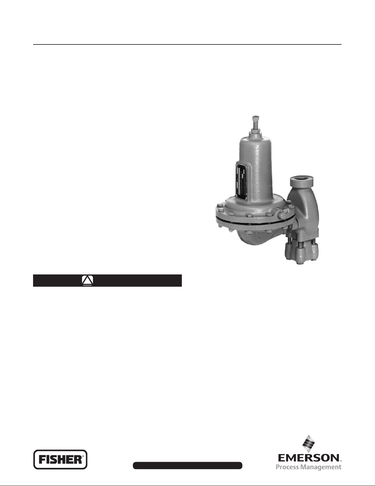
W1934
Figure 1. Spring-Loaded Type 630 Regulator
standard) to prevent service conditions
from exceeding those limits.
Additionally, physical damage to the
regulator could cause personal injury or
property damage due to escaping gas.
To avoid such injury or damage, install
the regulator in a safe location.
Before installing, inspect the unit for any damage and
any foreign material. The regulator or relief valve may
be mounted in any position, however, ensure that the
ow direction corresponds with the direction of the
arrow on the nameplate. Apply a good grade of pipe
compound to the male threads of the pipeline.
www.emersonprocess.com/regulators
D100300X012
630 Series
Specications
Available Congurations
Type 630: Spring-loaded reducing regulators
Type 630R: Spring-loaded relief valves
End Connection Sizes and Styles
1 or 2-inch NPT, CL150 RF, CL300 RF, or CL600 RF
Maximum Allowable Inlet Pressures
(1)
Type 630 Regulators: See Table 1
Type 630R Relief Valves: See Table 3
Type 630 Outlet Pressure Ranges
(1)
3 to 500 psig (0,21 to 34,5 bar) with intermediate
values shown in Table 2
Type 630R Relief Pressure Ranges
(1)
3 to 250 psig (0,21 to 17,2 bar)
See Table 3
Maximum Allowable Outlet Pressures
(1)
See Table 2
Maximum Allowable Pressure Drops
(1)
See Table 1
Pressure Registration
Spring Case Vent
1/4-inch NPT
Material Temperature Capabilities
Standard: -20° to 180°F (-29° to 82°C)
Optional: -20° to 300°F (-29° to 149°C)
Orice Sizes
1/8, 3/16, 1/4, 3/8,or 1/2-inch
(3,18; 4,76; 6,35; 9,53; or 12,7 mm)
Coefcients for Relief Valve Sizing
ORIFICE SIZE C
1/8-inch
1/4-inch
3/8-inch
1/2-inch
(3,18 mm)
(4,76 mm)
(6,35 mm)
(9,53 mm)
(12,7 mm)
3/16-inch
Approximate Weights
1-inch End Connection:
25 pounds (11,3 kg)
2-inch End Connection:
30 pounds (13,6 kg)
Internal
1. The pressure/temperature limits in this Instruction Manual or any applicable standard limitation should not be exceeded.
13.9
31.3
55.1
122.5
216.0
(1)
g
C
0.49
1.11
2.03
4.61
8.18
V
C
28.4
28.2
27.2
26.6
26.4
1
Table 1. Maximum Allowable Inlet Pressures and Pressure Drops. Maximum inlet pressure not to exceed 1500 psig (103 bar).
DISK MATERIAL
Nylon (PA) and
Polytetrauoroethylene (PTFE)
Nitrile (NBR)
Fluorocarbon (FKM)
MAXIMUM ALLOWABLE INLET
PRESSURE, PSIG (bar)
1. Inlet pressure must not exceed the sum of the actual outlet pressure setting and the maximum allowable pressure drop. For example, with an outlet pressure setting of 200 psig
(13,8 bar) and a 3/8-inch (9,53 mm) orice with a maximum allowable pressure drop of 500 psid (34,5 bar, differential), the maximum allowable inlet pressure is 700 psig (48,3 bar).
2. Nitrile (NBR) valve disks are normally furnished for pressure drops to 200 psi (13,8 bar, differential). For better erosion resistance, nylon valve disks are normally furnished for higher
pressure drops. Some erosion of valve disks occurs at all pressure drops due to solid particles in the ow stream. The rate of erosion is higher with large amounts of impurities in
the ow stream and with high pressure drops. Valve disks and other regulator parts must be inspected periodically for erosion and damage and must be replaced as necessary.
1/8 and 3/16 (3,17 and 4,76) 1/4 (6,35) 3/8 (9,52) 1/2 (12,7)
1500
(103)
600
(41,4)
200
(13,8)
1500 (103)
(1)
ORIFICE SIZE, INCHES (mm)
1000
(68,9)
600
(41,4)
200
(13,8)
1500 (103)
(1)
500
(34,5)
500
(34,5)
200
(13,8)
1000 (68,9)
250
(17,2)
250
(17,2)
200
(13,8)
(1)
750 (51,7)
(1)
Table 2. Type 630 Regulator Outlet Pressure Ranges and Maximum Outlet Pressures
REGULATOR
CONSTRUCTION
Low-Pressure
High-Pressure
1. Damage to internal parts of the regulator may occur if outlet pressure exceeds the actual pressure setting by amounts greater than those shown in this column.
2. For outlet pressure settings to 25 psig (1,72 bar) only. For pressure settings over 25 psig (1,72 bar), outlet pressure is limited by maximum emergency outlet pressure of 45 psig (3,10 bar).
3. For outlet pressure settings to 350 psig (24,1 bar) only. For pressure settings over 350 psig (24,1 bar), outlet pressure is limited by maximum emergency outlet pressure of
550 psig (37,9 bar).
4. Leakage or bursting of pressure-containing parts may occur if outlet pressure exceeds these values.
OUTLET PRESSURE
RANGE, PSIG (bar)
3 to 10 (0,21 to 0,69) 0W019227022 10 (0,69)
8 to 20 (0,55 to 1,38) 0W019127022 20 (1,38)
17 to 30 (1,17 to 2,07) 0W019027022 30 (2,07) 20
27 to 40 (1,86 to 2,76) 0Y066427022 40 (2,76)
27 to 50
(1,86 to 3,45)
46 to 95
90 to 150
150 to 200
200 to 275
275 to 500 (19,0 to 34,5) 1K370927082 500 (34,5) 200
(3,17 to 6,55)
(6,21 to 10,3)
(10,3 to 13,8)
(13,8 to 19,0)
SPRING
PART NUMBER
0W019227022
0W019127022
0W019027022
0Y066427022
1J146927142
MAXIMUM OPERATING
OUTLET PRESSURE,
PSIG (bar)
50
(3,45)
95
(6,55)
150
(10,3)
200
(13,8)
275
(19,0)
MAXIMUM OUTLET
PRESSURE OVER
SETPOINT
PSIG (bar)
20 (1,38)
Limited by Maximum
Emergency Outlet Pressure
200 (13,8)
(2)
(3)
(1,38)
(13,8)
(1)
,
MAXIMUM
EMERGENCY
OUTLET (CASING)
PRESSURE
PSIG (bar)
66 (4,55)
550 (37,9)
(4)
,
2
630 Series
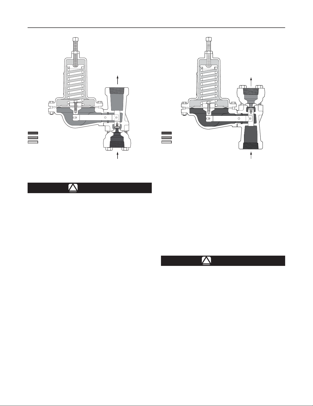
INLET PRESSURE
OUTLET PRESSURE
ATMOSPHERIC PRESSURE
46A2976-A
A2525-1
Figure 2. Type 630 Regulator Operational Schematic
Vents
WARNING
!
When the unit is installed in an enclosed
area or indoors, escaping gas may
accumulate and be an explosion hazard.
Under these conditions the vent should
be piped away from the unit to a freely
ventilated outdoor location away from air
intakes, windows, etc. Protect all vent
openings against weather or the entrance
of any foreign material that may plug the
vent or affect operation of the regulator
or relief valve. Inspect all vent openings
periodically to be sure they are not
plugged. If the vent is in an environment
where freezing rain, ice, or snow could
clog the vent, it is recommended that a
weatherproof vent be used.
Spring-loaded constructions have a screened vent
assembly (key 27, Figures 4, 5, and 6) installed in the
1/4-inch NPT spring case vent opening. If a remote
vent is required, remove the vent assembly and install
a remote vent line.
Overpressure Protection
As is the case with most regulators, the Type 630
spring-loaded regulators have outlet pressure
ratings that are lower than the inlet pressure ratings.
Overpressure protection must be provided if the
INLET PRESSURE
OUTLET PRESSURE
ATMOSPHERIC PRESSURE
46A2977
A2526-1
Figure 3. Type 630R Relief Valve Operational Schematic
actual inlet pressure can exceed the outlet pressure
rating. Overpressure protection is also required for the
loading regulator and main regulator spring case of
relief valves.
Refer to the following tables to determine pressure ratings:
1. Spring-loaded Type 630 regulators.
a. Inlet pressure and pressure drop—Table 1.
b. Outlet pressure—Table 2.
2. Spring-loaded Type 630R relief valve pressure Table 3.
WARNING
!
Overpressuring any portion of this
equipment may cause damage to
regulator parts, leaks in the regulator,
or personal injury due to bursting of
pressure-containing parts or explosion
of accumulated gas.
To avoid overpressure, provide an
appropriate overpressure protection
device to ensure that none of the limits
listed in Specications section, Tables 1
through 3 will be exceeded.
Regulator or relief valve operation below the limits
specied in Specications section, Tables 1 through 3
does not preclude the possibility of damage from external
sources or from debris in the gas line. Inspect the
regulator for damage after any overpressure condition.
3
630 Series
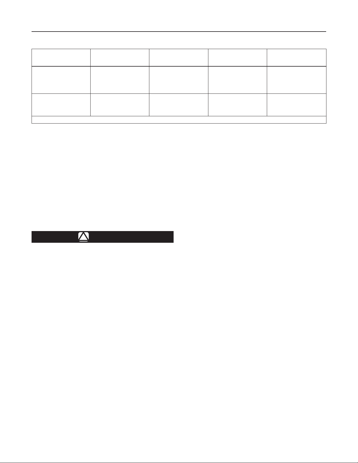
Table 3. Type 630R Relief Pressure Ranges
RELIEF VALVE
CONSTRUCTION
Low-Pressure
High-Pressure
1. Leakage or bursting of pressure-containing parts may occur if inlet pressure exceeds these values.
RELIEF (INLET)
PRESSURE RANGES,
PSIG (bar)
3 to 8
(0,21 to 0,55)
6 to 17
(0,41 to 1,17)
15 to 22
(1,03 to 1,52)
20 to 35
(1,38 to 2,41)
35 to 50
(2,41 to 3,45)
30 to 70
(2,07 to 4,83)
50 to 95
75 to 175
150 to 250
(3,45 to 6,55)
(5,17 to 12,1)
(10,3 to 17,2)
PART NUMBER
0W019227022
0W019127022
0W019027022
0Y066427022
1J146927142
0W019127022
0W019027022
0Y066427022
1J146927142
MAXIMUM ALLOWABLE
RELIEF (INLET)
PRESSURE, PSIG (bar)
Relief Pressure Setting Plus
Maximum Allowable Buildup
of 25 psig (1,72 bar)
Relief Pressure Setting Plus
Maximum Allowable Buildup
of 250 psig (17,2 bar)
MAXIMUM EMERGENCY
INLET (CASING)
PRESSURE
(1)
, PSIG (bar)
75 (5,17)
550 (37,9)
Startup
Starting up the unit consists of opening the upstream
block valve, introducing gas pressure. Use gauges to
monitor pressures during startup.
The range of allowable pressure settings is marked
on the nameplate. If a pressure setting beyond the
nameplate range is required, substitute an appropriate
spring selected from Table 5. Be sure to change the
nameplate to indicate the new pressure range.
WARNING
!
To avoid the consequences of
over-tightening the spring in
spring-loaded regulators or relief
valves, consult Table 4 and replace the
adjusting screw with one of the correct
length when replacing the spring.
Some pressure ratings are dependent upon the actual
outlet pressure settings being used. For example,
with a Type 630 regulator, outlet pressure must not
exceed the setting by more than 20 psig (1,38 bar)
for low pressure constructions or 200 psig (13,8 bar)
for high pressure constructions, or damage to internal
regulator parts may occur. However, with some higher
pressure ranges, the setting plus 20 psig (1,38 bar) or
200 psig (13,8 bar) exceeds the maximum emergency
outlet (casing) pressure. Before increasing the setting,
refer to Tables 2 and 3 (as appropriate). Review the
pressure limits for the spring range being used, and
be certain that the new pressure setting will not result
in an overpressure condition. Always use a pressure
gauge to monitor pressure when making adjustments.
Adjusting Spring-Loaded Regulators and
Relief Valves
Loosen the hex nut (key 2, Figures 4, 5, and 6) atop the
spring case. While monitoring the pressure, rotate the
adjusting screw (key 1, Figures 4, 5, and 6) clockwise to
increase set pressure or counterclockwise to decrease
it. When the unit is regulating or relieving pressure at
the desired value, tighten the hex nut.
Shutdown
Slowly close the upstream block valve.
Principle of Operation
This section describes the operation of the Type 630
regulator and the Type 630R relief valve with spring
loading. Set pressure is changed with the adjusting
screw on the regulator or relief valve. The Type 630R
relief valve uses a light spring for added stability.
Type 630 Regulators
Refer to Figure 2. In the regulator construction, outlet
pressure registers beneath the diaphragm. As long as
the outlet pressure is less than the set pressure, spring
force on the diaphragm causes the lever to hold the
valve open. When the outlet pressure exceeds the set
pressure, the diaphragm moves to compress the spring
and the lever closes the valve until the outlet pressure
returns to set pressure.
4
 Loading...