


Quick Installation Guide
00825-0100-4664, Rev BB
January 2013
Rosemount 8712 / 8700 Series
Rosemount 8712E Magnetic Flowmeter System
(Transmitter and Sensor)
Start
Step 1: Pre-Installation
Step 2: Handling
Step 3: Mounting
Step 4: Installation
(Flanged Sensors)
(Wafer Sensors)
(Sanitary Sensors)
Step 5: Grounding
Step 6: Wiring
Step 7: Basic Configuration
Product Certifications
End
www.rosemount.com

Quick Installation Guide
Rosemount 8712 / 8700 Series
00825-0100-4664, Rev BB
January 2013
© 2013 Rosemount Inc. All rights reserved. All marks property of owner.
Emerson Process Management Emerson Process |
Emerson FZE |
Emerson Process |
|||
Rosemount Flow |
Management Flow |
P.O. Box 17033 |
Management Asia Pacific |
||
7070 Winchester Circle, |
Neonstraat 1 |
Jebel Ali Free Zone |
Private Limited |
||
Dubai UAE |
|||||
Boulder, CO 80301 |
6718 WX Ede |
1 Pandan Crescent |
|||
Tel (USA) 800 522 6277 |
The Netherlands |
Tel +971 4 811 8100 |
Singapore 128461 |
||
Tel (International) +1 (303) 527 5200 |
T +31 (0)318 495555 |
Fax +971 4 886 5465 |
T (65) 6777 |
8211 |
|
Fax +1 (303) 530 8459 |
F +31(0) 318 495556 |
|
F (65) 6777 |
0947/65 6777 0743 |
|


 IMPORTANT NOTICE
This document provides basic installation guidelines for the Rosemount® 8712. It does not provide instructions for detailed configuration, diagnostics, maintenance, service, troubleshooting, explosion-proof, flame-proof, or intrinsically safe (I.S.) installations. Refer to the Rosemount 8712 reference manual (document number 00809-0100-4664) for more instructions. The manual and this QIG are also available electronically on www.rosemount.com.


 WARNING
Failure to follow these installation guidelines could result in death or serious injury:
Installation and servicing instructions are for use by qualified personnel only. Do not perform any servicing other than that contained in the operating instructions, unless qualified. Verify that the operating environment of the sensor and transmitter is consistent with the appropriate FM, CSA, ATEX, or IECEx approval.
Do not connect a Rosemount 8712 to a non-Rosemount sensor that is located in an explosive atmosphere.


 WARNING
The sensor liner is vulnerable to handling damage. Never place anything through the sensor for the purpose of lifting or gaining leverage. Liner damage can render the sensor useless.
To avoid possible damage to the sensor liner ends, do not use metallic or spiral-wound gaskets. If frequent removal is anticipated, take precautions to protect the liner ends. Short spool pieces attached to the sensor ends are often used for protection.
Correct flange bolt tightening is crucial for proper sensor operation and life. All bolts must be tightened in the proper sequence to the specified torque limits. Failure to observe these instructions could result in severe damage to the sensor lining and possible sensor replacement.
2

Quick Installation Guide
00825-0100-4664, Rev BB
January 2013
Rosemount 8712 / 8700 Series
STEP 1: PRE-INSTALLATION
Before installing the Rosemount 8712 Magnetic Flowmeter Transmitter, there are several pre-installation steps that should be completed to make the installation process easier:
•Identify the options and configurations that apply to your application
•Set the hardware switches if necessary
•Consider mechanical, electrical, and environmental requirements
Mechanical Considerations
The mounting site for the Rosemount 8712 transmitter should provide enough room for secure mounting, easy access to conduit ports, full opening of the transmitter covers, and easy readability of the LOI screen (see Figure 1).
The Rosemount 8712 is mounted separately from the sensor, it is not subject to limitations that might apply to the sensor.
3

Quick Installation Guide
Rosemount 8712 / 8700 Series
00825-0100-4664, Rev BB
January 2013
Figure 1. Rosemount 8712 Dimensional Drawing
WITH STANDARD COVER
4.31 |
(109) |
2.96 |
(75) |
9.01 |
|
|
|
(229) |
|
0.44 |
|
2.81 |
3.11 |
||
(11) |
|||
(71) |
(79) |
||
|
|||
|
|
12.02 |
|
|
|
(305) |
|
|
|
11.15 |
|
|
|
(283) |
WITH LOI COVER
Ground Lug |
1/2–14 NPT |
|
Conduit |
|
|
|
LOI Keypad |
|
|
Connection |
|
|
(4 Places) |
Cover |
NOTE
Dimensions are in inches (millimeters)
4

Quick Installation Guide
00825-0100-4664, Rev BB
January 2013
Rosemount 8712 / 8700 Series
Environmental Considerations
To ensure maximum transmitter life, avoid excessive heat and vibration. Typical problem areas include:
•Warm-climate installations in direct sunlight
•Outdoor installations in cold climates
Remote mounted transmitters may be installed in the control room to protect the electronics from the harsh environment and provide easy access for configuration or service.
Remotely mounted Rosemount 8712 transmitters require external power so there must be access to a suitable power source.
Installation Procedures
Rosemount 8712 installation includes both detailed mechanical and electrical installation procedures.
Mount the Transmitter
At a remote site the transmitter may be mounted on a pipe up to two inches in diameter or against a flat surface.
Pipe Mounting
To mount the transmitter on a pipe:
1.Attach the mounting plate to the pipe using the mounting hardware.
2.Attach the 8712 to the mounting plate using the mounting screws.
Identify Options and Configurations
The standard application of the 8712 includes a 4–20 mA output and control of the sensor coils and electrodes. Other applications may require one or more of the following configurations or options:
•Multidrop Communications
•Digital Output
•Digital Input
•Pulse Output
Additional options may apply. Be sure to identify those options and configurations that apply to your situation, and keep a list of them nearby for consideration during the installation and configuration procedures.
Hardware Jumpers/Switches
The 8712 electronics board is equipped with three user-selectable hardware switches. These switches set the Failure Alarm Mode, Internal/External Analog Power, and Transmitter Security. The standard configuration for these switches when shipped from the factory are as follows:
Failure Alarm Mode: |
HIGH |
Internal/External Analog Power: |
INTERNAL |
Transmitter Security: |
OFF |
Changing Hardware Switch Settings
In most cases, it is not necessary to change the setting of the hardware switches. If you need to change the switch settings, complete the steps outlined in the manual.
5
Quick Installation Guide
Rosemount 8712 / 8700 Series
00825-0100-4664, Rev BB
January 2013
Electrical Considerations
Before making any electrical connections to the Rosemount 8712, consider local and plant electrical standards and be sure to have the proper power supply, conduit, and other accessories necessary to comply with these standards.
STEP 2: HANDLING
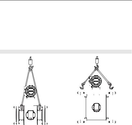
Handle all parts carefully to prevent damage. Whenever possible, transport the system to the installation site in the original shipping containers. PTFE-lined sensors are shipped with end covers that protect it from both mechanical damage and normal unrestrained distortion. Remove the end covers just before installation.
Figure 2. Rosemount 8705 Sensor Support for Handling
|
|
|
|
|
|
|
|
|
|
|
|
|
|
|
|
|
|
|
|
|
|
|
|
|
|
|
|
|
|
|
|
|
|
|
|
|
|
|
|
|
|
|
|
|
|
|
|
|
|
|
|
|
|
|
|
|
|
|
|
|
|
|
|
|
|
|
|
|
|
|
|
|
|
|
|
|
|
|
|
|
|
|
|
|
|
|
|
|
|
|
|
|
|
|
|
|
|
|
|
|
|
|
|
|
|
|
|
|
|
|
|
|
|
|
|
|
|
|
|
|
|
|
|
|
|
|
|
|
|
|
|
|
|
|
|
|
|
|
|
|
|
|
|
|
|
|
|
|
|
|
|
|
|
|
|
|
|
|
|
|
|
|
|
|
|
|
|
|
|
|
|
|
|
|
|
|
|
|
|
|
|
|
|
|
|
|
|
|
|
|
|
|
|
|
|
|
|
|
|
|
|
|
|
|
|
|
|
|
|
|
|
|
|
|
|
|
|
|
|
|
|
|
|
|
|
|
|
|
|
|
|
|
|
|
|
|
|
|
|
|
|
|
|
|
|
|
|
|
|
|
|
|
|
|
|
|
|
|
|
|
|
|
|
|
|
|
|
|
|
|
|
|
|
|
|
|
|
|
|
|
|
|
|
|
|
|
|
|
|
|
|
|
|
|
|
|
|
|
|
|
|
|
|
|
|
|
|
|
|
|
|
|
|
|
|
|
|
|
|
|
|
|
|
|
|
|
|
|
|
|
|
|
|
|
|
|
|
|
|
|
|
|
|
|
|
|
|
|
|
|
|
|
|
|
|
|
|
|
|
|
|
|
|
|
|
|
|
|
|
|
|
|
|
|
|
|
|
|
|
|
|
|
|
|
|
|
|
|
|
|
|
|
|
|
|
|
|
|
|
|
|
|
|
|
|
|
|
|
|
|
|
|
|
|
|
|
|
|
|
|
|
|
|
|
|
|
|
|
|
|
|
|
|
|
|
|
|
|
|
|
|
|
|
|
|
|
|
|
|
|
|
|
|
|
|
|
|
|
|
|
|
|
|
|
|
|
|
|
|
|
|
|
|
|
|
|
|
|
|
|
|
|
|
|
|
|
|
|
|
|
|
|
|
|
|
|
|
|
|
|
|
|
|
|
|
|
|
|
|
|
|
|
|
|
|
|
|
|
|
|
|
|
|
|
|
|
|
|
|
|
|
|
|
|
|
|
|
|
|
|
|
|
|
|
|
|
|
|
|
|
|
|
|
|
|
|
|
|
|
|
|
|
|
|
|
|
|
|
|
|
|
|
|
|
|
|
|
|
|
|
|
|
|
|
|
|
|
|
|
|
|
|
|
|
|
|
|
|
|
|
|
|
|
|
|
|
|
|
|
|
|
|
|
|
|
|
|
|
|
|
|
|
|
|
|
|
|
|
|
|
|
|
|
|
|
|
|
|
|
|
|
|
|
|
|
|
|
|
|
|
|
|
|
|
|
|
|
|
|
½- through 4-Inch Sensors |
|
|
|
|
6-Inch and Larger Sensors |
||||||||||||||||||||||||||||||||||||||||||||||||||||||
6
Quick Installation Guide
00825-0100-4664, Rev BB
January 2013
Rosemount 8712 / 8700 Series
STEP 3: MOUNTING
Upstream/Downstream Piping
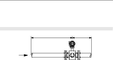
To ensure specification accuracy over widely varying process conditions, install the sensor a minimum of five straight pipe diameters upstream and two pipe diameters downstream from the electrode plane (see Figure 3).
Figure 3. Upstream and Downstream Straight Pipe Diameters
5 Pipe Diameters |
2 Pipe Diameters |
Flow |
|
Installations with reduced straight runs from 0 to 5 pipe diameters are possible. In reduced straight pipe run installations, performance will shift to as much as 0.5% of rate. Reported flow rates will still be highly repeatable.
Flow Direction
The sensor should be mounted so the FORWARD end of the flow arrow, shown on the sensor identification tag, points in the direction of flow through the sensor.
Sensor Orientation
The sensor should be installed in a position that ensures the sensor remains full during operation. Vertical installation allows upward process fluid flow and keeps the cross-sectional area full, regardless of flow rate. Horizontal installation should be restricted to low piping sections that are normally full. In these cases, orient the electrode plane to within 45° of horizontal.
7
Quick Installation Guide
Rosemount 8712 / 8700 Series
00825-0100-4664, Rev BB
January 2013
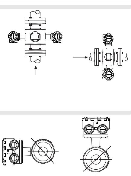
Figure 4. Sensor Orientation
FLOW
FLOW
The electrodes in the Rosemount 8705 sensor are properly orientated when the two measurement electrodes are in the 3 and 9 o’clock positions, as shown on the right of Figure 4.
The electrodes in the Rosemount 8711 are properly orientated when the top of the sensor is either vertical or horizontal, as shown in Figure 5. Avoid any mounting orientation that positions the top of the sensor at 45° from the vertical or horizontal position.
Figure 5. Rosemount 8711 Mounting Position
45° Electrode Plane
45° Electrode Plane
8
Quick Installation Guide
00825-0100-4664, Rev BB
January 2013
Rosemount 8712 / 8700 Series
STEP 4: INSTALLATION
Flanged Sensors
Gaskets
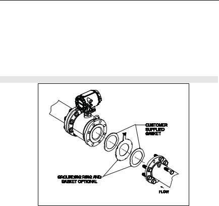
The sensor requires a gasket at each of its connections to adjacent devices or piping. The gasket material selected must be compatible with the process fluid and operating conditions. Metallic or spiral-wound gaskets can damage the liner. Gaskets are required on each side of a grounding ring. All other applications (including sensors with lining protectors or a grounding electrode) require only one gasket on each end connection.
Figure 6. Flanged gasket placement
Flange Bolts
NOTE
Do not bolt one side at a time. Tighten each side simultaneously. Example:
1.Snug left
2.Snug right
3.Tighten left
4.Tighten right
Do not snug and tighten the upstream side and then snug and tighten the downstream side. Failure to alternate between the upstream and downstream flanges when tightening bolts may result in liner damage.
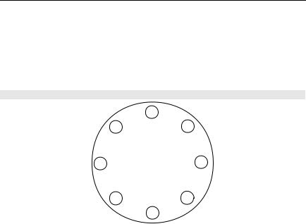
Suggested torque values by sensor line size and liner type are listed in Table 1 for ASME B16.5 (ANSI) and Table 2 for DIN flanges. Consult the factory if the flange rating of the sensor is not listed. Tighten flange bolts on the upstream side of the sensor in the incremental sequence shown in Figure 7, to 20% of the suggested torque values. Repeat the process on the downstream side of the sensor. For sensors with more or less flange bolts, tighten the bolts in a similar crosswise sequence. Repeat this entire tightening sequence at 40%, 60%, 80%, and 100% of the suggested torque values or until the leak between the process and sensor flanges stop.
9
Quick Installation Guide
Rosemount 8712 / 8700 Series
00825-0100-4664, Rev BB
January 2013
If leakage has not stopped at the suggested torque values, the bolts can be tightened in additional 10% increments until the joint stops leaking, or until the measured torque value reaches the maximum torque value of the bolts. Practical consideration for the integrity of the liner often leads the user to distinct torque values to stop leakage due to the unique combinations of flanges, bolts, gaskets, and sensor liner material.
Check for leaks at the flanges after tightening the bolts. Failure to use the correct tightening methods can result in severe damage. Sensors require a second tightening 24 hours after the initial installation. Over time, sensor liner materials may deform under pressure.
Figure 7. Flange Bolt Torquing Sequence
8 |
1 |
5 |
|
||
4 |
8-bolt |
3 |
|
||
|
|
|
6 |
2 |
7 |
|
|
Table 1. Suggested Flange Bolt Torque Values for Rosemount 8705 and 8707 High-Signal Sensors
|
|
PTFE/ETFE/PFA |
Polyurethane/Neoprene/Linatex/Adiprene |
|||
|
|
liners |
|
liner |
||
Size |
|
Class 150 |
Class 300 |
Class 150 |
|
Class 300 |
Code |
Line Size |
(pound-feet) |
(pound-feet) |
(pound-feet) |
|
(pound-feet) |
005 |
0.5 inch (15 mm) |
8 |
8 |
- |
|
- |
010 |
1 inch (25 mm) |
8 |
12 |
- |
|
- |
015 |
1.5 inch (40 mm) |
13 |
25 |
7 |
|
18 |
020 |
2 inch (50 mm) |
19 |
17 |
14 |
|
11 |
030 |
3 inch (80 mm) |
34 |
35 |
23 |
|
23 |
040 |
4 inch (100 mm) |
26 |
50 |
17 |
|
32 |
060 |
6 inch (150mm) |
45 |
50 |
30 |
|
37 |
080 |
8 inch (200 mm) |
60 |
82 |
42 |
|
55 |
100 |
10 inch (250 mm) |
55 |
80 |
40 |
|
70 |
120 |
12 inch (300 mm) |
65 |
125 |
55 |
|
105 |
140 |
14 inch (350 mm) |
85 |
110 |
70 |
|
95 |
160 |
16 inch (400 mm) |
85 |
160 |
65 |
|
140 |
180 |
18 inch (450 mm) |
120 |
170 |
95 |
|
150 |
200 |
20 inch (500 mm) |
110 |
175 |
90 |
|
150 |
240 |
24 inch (600 mm) |
165 |
280 |
140 |
|
250 |
300 |
30 inch (750 mm) |
195 |
415 |
165 |
|
375 |
360 |
36 inch (900 mm) |
280 |
575 |
245 |
|
525 |
10
 Loading...