


Instruction Manual
PN 51-5081T/rev.D
February 2006
Model 5081-T
Two-Wire Toroidal Conductivity Transmitter

ESSENTIAL INSTRUCTIONS
READ THIS PAGE BEFORE PROCEEDING!
Rosemount Analytical designs, manufactures, and tests its products to meet many national and international standards. Because these instruments are sophisticated technical products, you must properly install, use, and maintain them to ensure they continue to operate within their normal specifications. The following instructions must be adhered to and integrated into your safety program when installing, using, and maintaining Rosemount Analytical products. Failure to follow the proper instructions may cause any one of the following situations to occur: Loss of life; personal injury; property damage; damage to this instrument; and warranty invalidation.
•Read all instructions prior to installing, operating, and servicing the product. If this Instruction Manual is not the correct manual, telephone 1-800-654-7768 and the requested manual will be provided. Save this Instruction Manual for future reference.
•If you do not understand any of the instructions, contact your Rosemount representative for clarification.
•Follow all warnings, cautions, and instructions marked on and supplied with the product.
•Inform and educate your personnel in the proper installation, operation, and maintenance of the product.
•Install your equipment as specified in the Installation Instructions of the appropriate Instruction Manual and per applicable local and national codes. Connect all products to the proper electrical and pressure sources.
•To ensure proper performance, use qualified personnel to install, operate, update, program, and maintain the product.
•When replacement parts are required, ensure that qualified people use replacement parts specified by Rosemount. Unauthorized parts and procedures can affect the product’s performance and place the safe operation of your process at risk. Look alike substitutions may result in fire, electrical hazards, or improper operation.
•Ensure that all equipment doors are closed and protective covers are in place, except when maintenance is being performed by qualified persons, to prevent electrical shock and personal injury.
CAUTION
If a Model 375 Universal Hart® Communicator is used with these transmitters, the software within the Model 375 may require modification. If a software modification is required, please contact your local Emerson Process Management Service Group or National Response Center at 1-800-654-7768.
About This Document
This manual contains instructions for installation and operation of the Model 5081-T Two-Wire Conductivity Transmitter. The following list provides notes concerning all revisions of this document.
Rev. Level |
Date |
Notes |
A |
1/05 |
This is the initial release of the product manual. The manual has been |
|
|
reformatted to reflect the Emerson documentation style and updated to |
|
|
reflect any changes in the product offering. This manual contains |
|
|
information on HART Smart and FOUNDATION Fieldbus versions of |
|
|
Model 5081-T. |
B |
5/05 |
Fix LED font on pages 4, 30, 34, 35, 39. |
C |
10/05 |
Add instructions to enable autoranging or fixed measurement renges on |
|
|
page 50. |
D |
2/06 |
Add FISCO agency certifications drawings, pp. 30-36. |
Emerson Process Management
Rosemount Analytical Inc.
2400 Barranca Parkway
Irvine, CA 92606 USA
Tel: (949) 757-8500
Fax: (949) 474-7250
http://www.raihome.com
© Rosemount Analytical Inc. 2006
MODEL 5081-T |
TABLE OF CONTENTS |
|
MODEL 5081-T |
|
|
TWO-WIRE TRANSMITTER |
|
|
TABLE OF CONTENTS |
|
Section |
Title |
Page |
1.0 |
DESCRIPTION AND SPECIFICATIONS ................................................................ |
1 |
1.1 |
Features and Applications........................................................................................ |
1 |
1.2 |
Specifications........................................................................................................... |
2 |
1.3 |
Hazardous Location Approval.................................................................................. |
3 |
1.4 |
Transmitter Display During Calibration and Programming....................................... |
4 |
1.5 |
Infrared Remote Controller ...................................................................................... |
4 |
1.6 |
HART Communications ........................................................................................... |
5 |
1.7 |
FOUNDATION Fieldbus............................................................................................... |
6 |
1.8 |
Asset Management Solutions ................................................................................. |
6 |
2.0 |
INSTALLATION ....................................................................................................... |
8 |
2.1 |
Unpacking and Inspection........................................................................................ |
8 |
2.2 |
Orienting the Display Board..................................................................................... |
8 |
2.3 |
Mechanical Installation............................................................................................. |
8 |
2.4 |
Power Supply/Current Loop Wiring for Model 5081-T-HT ....................................... |
12 |
2.5 |
Power Supply Wiring for Model 5081-T-FF/FI.......................................................... |
13 |
3.0 |
WIRING.................................................................................................................... |
14 |
3.1 |
Sensor Wiring .......................................................................................................... |
14 |
3.2 |
Electrical Installation ................................................................................................ |
16 |
4.0 |
INTRINSICALLY SAFE AND EXPLOSION PROOF INSTALLATIONS.................. |
19 |
4.1 |
Intrinsically Safe and Explosion-Proof Installation for Model 5081-T-HT ................. |
19 |
4.2 |
Intrinsically Safe and Explosion-Proof Installation for Model 5081-T-FF ................. |
25 |
4.3 |
Intrinsically Safe and Explosion-Proof Installation for Model 5081-T-FI .................. |
30 |
5.0 |
DISPLAY AND OPERATION................................................................................... |
37 |
5.1 |
Displays ................................................................................................................... |
37 |
5.2 |
Infrared Remote Controller (IRC) — Key Functions ................................................ |
38 |
5.3 |
Quick Start for Model 5081-T-HT ............................................................................. |
39 |
5.4 |
Quick Start for Model 5081-T-FF/FI ......................................................................... |
40 |
5.5 |
Menu Tree................................................................................................................ |
41 |
5.6 |
Diagnostic Messages............................................................................................... |
43 |
5.7 |
Default Setting ......................................................................................................... |
43 |
5.8 |
Security .................................................................................................................... |
45 |
5.9 |
Using Hold ............................................................................................................... |
45 |
6.0 |
START-UP AND CALIBRATION ............................................................................. |
46 |
6.1 |
Accessing the Calibrate Menu ................................................................................. |
46 |
6.2 |
Calibrate Menu......................................................................................................... |
47 |
....................................................................................Continued on following page
i
MODEL 5081-T |
TABLE OF CONTENTS |
|
TABLE OF CONTENTS CONT’D |
|
7.0 |
PROGRAMMING..................................................................................................... |
50 |
7.1 |
General .................................................................................................................... |
50 |
7.2 |
Output ...................................................................................................................... |
51 |
7.3 |
Temp ........................................................................................................................ |
53 |
7.4 |
Display ..................................................................................................................... |
54 |
7.5 |
HART ....................................................................................................................... |
55 |
7.6 |
Setup Cust ............................................................................................................... |
56 |
7.7 |
Range ...................................................................................................................... |
57 |
7.8 |
Default...................................................................................................................... |
57 |
8.0 |
FOUNDATION FIELDBUS OPERATION................................................................ |
58 |
9.0 |
OPERATION WITH MODEL 375............................................................................. |
59 |
9.1 |
Note on Model 375 or 275 Communicator............................................................... |
59 |
9.2 |
Connecting the Communicator ................................................................................ |
59 |
9.3 |
Operation ................................................................................................................. |
60 |
10.0 |
DIAGNOSIS AND TROUBLESHOOTING............................................................... |
75 |
10.1 |
Overview .................................................................................................................. |
75 |
10.2 |
Fault Conditions....................................................................................................... |
77 |
10.3 |
Diagnostic Messages............................................................................................... |
78 |
10.4 |
Quick Troubleshooting Guide................................................................................... |
79 |
10.5 |
Systematic Troubleshooting..................................................................................... |
80 |
10.6 |
RTD Resistance Values ........................................................................................... |
81 |
10.7 |
Warning and Fault Messages .................................................................................. |
82 |
10.8 |
Troubleshooting When a Fault or Warning Message is Showing ............................ |
83 |
11.0 |
MAINTENANCE ...................................................................................................... |
86 |
11.1 |
Overview .................................................................................................................. |
86 |
11.2 |
Preventative Maintenance ....................................................................................... |
86 |
11.3 |
Corrective Maintenance........................................................................................... |
86 |
12.0 |
THEORY OF OPERATION ..................................................................................... |
89 |
12.1 |
Overview .................................................................................................................. |
89 |
12.2 |
Conductivity ............................................................................................................. |
89 |
12.3 |
HART Communication ............................................................................................. |
89 |
12.4 |
Output Logic............................................................................................................. |
89 |
13.0 |
RETURN OF MATERIAL......................................................................................... |
91 |
ii
MODEL 5081-T |
TABLE OF CONTENTS |
LIST OF FIGURES
Number |
Title |
Page |
1-1 |
Transmitter Display During Calibration and Programming ....................................... |
4 |
1-2 |
Infrared Remote Controller....................................................................................... |
4 |
1-3 |
HART Communicator ............................................................................................... |
5 |
1-4 |
Configuring Model 5081-T Transmitter with Foundation Fieldbus............................ |
6 |
1-5 |
AMS Main Menu Tools ............................................................................................. |
7 |
2-1 |
Mounting the Model 5081-T Transmitter on a Flat Surface ...................................... |
9 |
2-2 |
Using the Pipe Mounting Kit to Attach the Model 5081-T to a pipe .......................... |
10 |
2-3 |
Load/Power Supply Wiring Requirements................................................................ |
12 |
2-4 |
Model 5081-T-HT Power Wiring Details ................................................................... |
12 |
2-5 |
Typical Fieldbus Network Electrical Wiring Configuration ........................................ |
13 |
2-6 |
Model 5081-T-FF Power Wiring Details ................................................................... |
13 |
3-1 |
Wiring Model 5081-T-HT .......................................................................................... |
14 |
3-2 |
Power Supply/Current Loop Wiring for Model 5081-T-HT........................................ |
15 |
3-3 |
Power Supply/Current Loop Wiring for Model 5081-T-FF ........................................ |
15 |
3-4 |
Power Supply and Sensor Wiring for Model 5081-T ................................................ |
15 |
3-5 |
Wiring Model 242 Sensor to Model 5081-T Transmitter .......................................... |
16 |
3-6 |
Wiring Models 222, 225, 226, 228, 242, 247 to Model 5081-T Transmitter................. |
17 |
3-7 |
Wiring Models 222, 225, 226, 228 to Model 5081-T Transmitter ................................ |
18 |
4-1 |
Model 5081-T-HT Infrared Remote Control — CSA, FM, & ATEX approvals........... |
19 |
4-2 |
Model 5081-T-FF Infrared Remote Control — CSA, FM, & ATEX approvals ........... |
19 |
4-3 |
FM Explosion-Proof Installation for Model 5081-T-HT ............................................. |
20 |
4-4 |
FM Intrinsically Safe Installation for Model 5081-T-HT............................................. |
21 |
4-5 |
CSA Intrinsically Safe Installation for Model 5081-T-HT........................................... |
22 |
4-6 |
ATEX Intrinsically Safe Label for Model 5081-T-HT ................................................. |
23 |
4-7 |
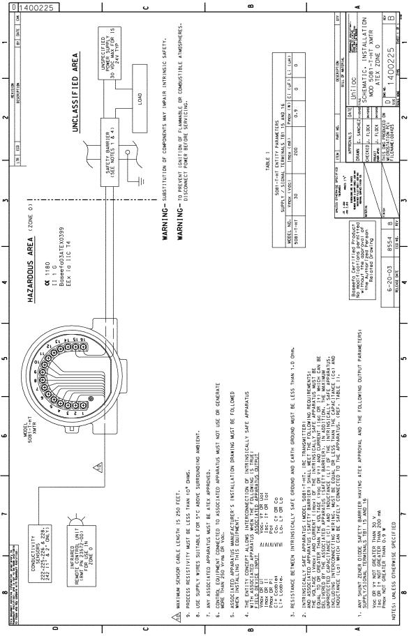
ATEX Intrinsically Safe Installation for Model 5081-T-HT......................................... |
24 |
4-8 |
FM Explosion-Proof Installation for Model 5081-T-FF.............................................. |
25 |
4-9 |
FM Intrinsically Safe Installation for Model 5081-T-FF ............................................. |
26 |
4-10 |
CSA Intrinsically Safe Installation for Model 5081-T-FF ........................................... |
27 |
4-11 |
ATEX Intrinsically Safe Label for Model 5081-T-FF ................................................. |
28 |
4-12 |
ATEX Intrinsically Safe Installation for Model 5081-T-FF ......................................... |
29 |
4-13 |
FM Explosion-Proof Installation for Model 5081-T-FI ............................................... |
30 |
4-14 |
FM Intrinsically Safe Label for Model 5081-T-FI....................................................... |
31 |
4-15 |
FM Intrinsically Safe Installation for Model 5081-T-FI .............................................. |
32 |
4-16 |
CSA Intrinsically Safe Label for Model 5081-T-FI..................................................... |
33 |
4-17 |
CSA Intrinsically Safe Installation for Model 5081-T-FI ............................................ |
34 |
4-18 |
ATEX Intrinsically Safe Label for Model 5081-T-FI................................................... |
35 |
4-19 |
ATEX Intrinsically Safe Installation for Model 5081-T-FI .......................................... |
36 |
iii
MODEL 5081-T |
TABLE OF CONTENTS |
LIST OF FIGURES - CONT’D
Number |
Title |
Page |
5-1 |
Process Display Screen ........................................................................................... |
37 |
5-2 |
Program Display Screen .......................................................................................... |
37 |
5-3 |
Infrared Remote Controller....................................................................................... |
38 |
5-4 |
Menu Tree for Model 5081-T-HT .............................................................................. |
41 |
5-5 |
Menu Tree for Model 5081-T-FF ............................................................................. |
42 |
6-1 |
Menu Tree ............................................................................................................... |
46 |
6-2 |
Current Output Calibration ....................................................................................... |
47 |
8-1 |
Functional Block Diagram for the Model 5081-T with FOUNDATION Fieldbus.......... |
58 |
9-1 |
Connecting the HART Communicator ...................................................................... |
59 |
9-2 |
5081-T-HT HART/Model 375 Menu Tree.................................................................. |
61 |
9-3 |
5081-T-FF/FI Model 375 Menu Tree ........................................................................ |
65 |
10-1 |
Diagnose Menu Segments ....................................................................................... |
75 |
10-2 |
Disabling Fault Annunciation .................................................................................... |
77 |
10-3 |
Warning Annunciation............................................................................................... |
77 |
10-4 |
Troubleshooting Flow Chart ..................................................................................... |
80 |
10-5 |
Conductivity Determination ...................................................................................... |
81 |
11-1 |
Hold Annunciation .................................................................................................... |
86 |
LIST OF TABLES
Number |
Title |
Page |
5-1 |
Default Settings fro Model 5081-T-FF ...................................................................... |
43 |
5-2 |
Default Settings fro Model 5081-T-HT...................................................................... |
44 |
6-1 |
Calibrate Menu Mnemonics...................................................................................... |
49 |
10-1 |
Diagnostic Variables Mnemonics ............................................................................. |
76 |
10-2 |
Diagnostic Fault Messages ...................................................................................... |
78 |
10-3 |
Quick Troubleshooting Guide ................................................................................... |
79 |
10-4 |
RTD Resistance Values............................................................................................ |
81 |
11-1 |
Model 5081-T Replacement Parts and Accessories................................................. |
87 |
iv
MODEL 5081-T |
SECTION 1.0 |
|
DESCRIPTION AND SPECIFICATIONS |
SECTION 1.0
DESCRIPTION AND SPECIFICATIONS
•CHOICE OF COMMUNICATION PROTOCOL: HART or FOUNDATION Fieldbus.
•LARGE, EASY-TO-READ two-line display shows the process measurement and temperature.
•SIMPLE MENU STRUCTURE.
•ROBUST NEMA 4X and NEMA 7B ENCLOSURE.
•INTRINSICALLY SAFE DESIGN allows the transmitter to be used in hazardous environments (with appropriate safety barriers).
•NON-VOLATILE MEMORY retains program settings and calibration data during power failures.
•MEASURES CONDUCTIVITY, % CONCENTRATION, PPM, OR CUSTOM CURVE VARIABLE.
•AUTOMATIC TC RECOGNITION simplifies start up.
•AUTOMATIC/MANUAL TEMPERATURE COMPENSATION ensures accurate monitoring and control.
•AUTOMATIC COMPENSATION FOR SENSOR CABLE RESISTANCE improves accuracy of high conductivity/ low resistivity measurements.
•BUILT-IN PERCENT CONCENTRATION CURVES INCLUDE 0-15% NaOH, 0-16% HCl, 0-30% and 96-99.7% H2SO4.
1.1 FEATURES AND APPLICATIONS
The Model 5081-T can be used to measure conductivity in a variety of process liquids. The 5081 is compatible with most Rosemount Analytical sensors. See the Specifications section for details.
The transmitter has a rugged, weatherproof, corrosionresistant enclosure (NEMA 4X and IP65) of epoxy-painted aluminum. The enclosure also meets NEMA 7B explo- sion-proof standards.
The transmitter has a two-line seven-segment display. The main measurement appears in 0.8-inch (20 mm) high numerals. The secondary measurement, temperature (and pH if free chlorine is being measured), appears in 0.3-inch (7 mm) high digits.
Two digital communication protocols are available: HART (model option -HT) and FOUNDATION Fieldbus (model options -FF and FI). Digital communications allows access to AMS (Asset Management Solutions). Use AMS to set up and configure the transmitter, read process variables, and troubleshoot problems from a personal computer or host anywhere in the plant.
A handheld infrared remote controller or the HART and FOUNDATION Fieldbus Model 375 communicator can also be used for programming and calibrating the transmitter. The remote controller works from as far away as six feet.
Housed in a rugged NEMA 4X and NEMA 7 case, the 5081T measures conductivity or resistivity in the harshest environments. Transmitter can also be configured, using the "Custom Curve" feature, to measure ppm, %, or a no unit variable according to a programmable conductivity vs. variable curve. The transmitter will automatically recognize the type of RTD (Pt100 or Pt1000) being used. Measurements are automatically corrected for the resistance of the sensor cable to improve accuracy of high conductivity readings. Temperature compensation choices are linear slope correction or none (display of raw conductivity.
1
MODEL 5081-T |
SECTION 1.0 |
|
DESCRIPTION AND SPECIFICATIONS |
1.2 SPECIFICATIONS
1.2.1 GENERAL SPECIFICATIONS
Enclosure: Cast aluminum containing less than 6% magnesium, with epoxy polyester coating. NEMA 4X (IP65) and NEMA 7B. Neoprene O-ring cover seals.
Dimensions: See drawing.
Conduit Openings: ¾-in. FNPT
Ambient Temperature: -4 to 149°F (-20 to 65°C)
Storage Temperature: -22 to 176°F (-30 to 80°C)
Relative Humidity: 0 to 95% (non-condensing)
Weight/Shipping Weight: 10 lb/10 lb (4.5/5.0 kg)
Display: Two-line LCD; first line shows process variable (pH, ORP, conductivity, % concentration, oxygen, ozone, or chlorine), second line shows process temperature and output current. For pH/chlorine combination, the second line can be toggled to show pH. Fault and warning messages, when triggered, alternate with temperature and output readings.
First line: 7 segment LCD, 0.8 in. (20 mm) high.
Second line: 7 segment LCD, 0.3 in. (7mm) high.
Display board can be rotated 90 degrees clockwise or counterclockwise.
During calibration and programming, messages and prompts appear in the second line.
Temperature resolution: 0.1°C
Hazardous Location Approval: For details, see specifications for the measurement of interest.
RFI/EMI: EN-61326
Digital Communications:
HART —
Power & Load Requirements:
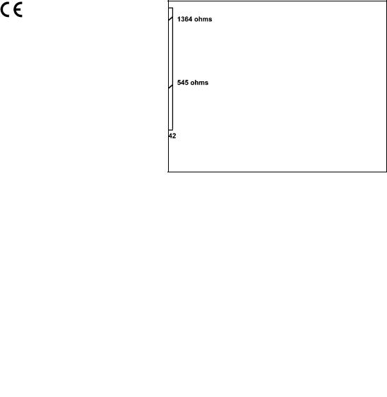
Supply voltage at the transmitter terminals should be at least 12 Vdc. Power supply voltage should cover the voltage drop on the cable plus the external load resistor required for HART communications (250 Ω minimum). Minimum power supply voltage is 12 Vdc. Maximum power supply voltage is 42.4 Vdc (30 Vdc for intrinsically safe operation). The graph shows the supply voltage required to maintain 12 Vdc (upper line) and 30 Vdc (lower line) at the transmitter terminals when the current is 22 mA.
Analog Output: Two-wire, 4-20 mA output with superimposed HART digital signal. Fully scalable over the operating range of the sensor.
Output accuracy: ±0.05 mA
HART option
FOUNDATION FIELDBUS —
Power & Load Requirements: A power supply voltage of 9-32 Vdc at 22 mA is required.
1.2.2 FUNCTIONAL SPECIFICATIONS
Calibration: Calibration is easily accomplished by immersing the sensor in a known solution and entering its value.
Automatic Temperature Compensation:
3-wire Pt 100 RTD
Conductivity: 0 to 200°C (32 to 392°F)
% Concentration: 0 to 100°C (32 to 212°F)
Diagnostics: The internal diagnostics can detect:
Calibration Error |
Zero Error |
Temperature Slope Error |
Low Temperature Error |
High Temperature Error |
Sensor Failure |
Line Failure |
CPU Failure |
ROM Failure |
Input Warning |
Once one of the above is diagnosed, the LCD will display a message describing the failure/default detected.
Digital Communications:
HART: PV, SV, and TV assignable to measurement (conductivity, resistivity, or concentration), temperature, and raw conductivity. Raw conductivity is measured conductivity before temperature correction.
Fieldbus: Three AI blocks assignable to measurement (conductivity, resistivity, or concentration), temperature, and raw conductivity. Raw conductivity is measured conductivity before temperature correction.
Execution time 75 msec. One PID block; execution time 150 msec. Device type: 4084. Device revision: 1. Certified to ITK 4.5.
2

MODEL 5081-T |
SECTION 1.0 |
|
DESCRIPTION AND SPECIFICATIONS |
1.2.3 TRANSMITTER SPECIFICATIONS @ 25°C Measured Range*: 50 to 2,000,000 µS/cm (see chart) Accuracy: ± 1.0% of reading
Repeatability: ± 0.25% of reading
Stability: 0.25% of output range/month, non-cumulative
Ambient Temperature Coefficient: ± 0.2% of FS/°C Temperature Slope Adjustment: 0-5%/° C
%Concentration Ranges:
Sodium Hydroxide: 0 to 15% Hydrochloric Acid: 0 to 16%
Sulfuric Acid: 0 to 25% and 96 to 99.7%
1.2.4 LOOP SPECIFICATIONS
Loop Accuracy: With a standard Model 228 or 225 sensor with 20' cable, laboratory accuracy at 25°C can be as good as ±2% of reading and ±50 µS/cm.
To achieve optimum performance, standardize the sensor in the process at the conductivity and temperature of interest.
Results under real process conditions, at different temperatures, or using other sensors may differ from above.
RTD accuracy: Utilizing a perfect 100 Ohm RTD after 1 point temperature standardization, temperature reading can be as good as ±0.5°C.
1.3 HAZARDOUS LOCATION APPROVAL
Intrinsic Safety:
Class I, II, III, Div. 1
Groups A-G
T4 Tamb = 70°C
Exia Entity
Class I, Groups A-D
Class II, Groups E-G
Class III
T4 Tamb = 70°C
ATEX |
1180 |
II |
1 G |
Baseefa03ATEX0399
EEx ia IIC T4
Tamb = -20°C to +65°C
Non-Incendive:
Class I, Div. 2, Groups A-D
Dust Ignition Proof
Class II & III, Div. 1, Groups E-G
NEMA 4X Enclosure
RECOMMENDED SENSORS:
Model 222 |
Flow-Through |
Class I, Div. 2, Groups A-D |
|
Suitable for |
|||
Model 225 |
Clean-In-Place (CIP) |
||
|
|||
Model 226 |
Submersion/Insertion |
Class II, Div. 2, Groups E-G |
|
|
|||
Model 228 |
Submersion/Insertion/Retractable |
T4 Tamb = 70°C |
Model 242* Flow-Through
*no I.S. approval for loops of 5081-T with 242-06 or 242-08
Explosion-Proof:
Class I, Div. 1, Groups B-D
Class II, Div. 1, Groups E-G
Class III, Div. 1
Class I, Groups B-D
Class II, Groups E-G
Class III
Tamb = 65°C max
RECOMMENDED RANGES FOR TOROIDAL SENSORS |
|
|
|||||
Conductivity Sensor |
|
|
|
|
|
|
|
Model Number |
226 |
228 |
225 |
222 (1in.) |
222 (2 in.) |
242 |
|
Nominal Cell Constant |
1.0 |
3.0 |
3.0 |
6.0 |
4.0 |
* |
|
Minimum Conductivity (µS/cm) |
50 |
200 |
200 |
500 |
500 |
100* |
|
|
|
|
|
|
|
|
|
Maximum Conductivity (µS/cm) |
1,000,000 |
2,000,000 |
2,000,000 |
2,000,000 |
2,000,000 |
2,000,000* |
|
|
|
|
|
|
|
|
|
* Model 242 values depend on sensor configuration and wiring. |
|
|
|
3 |
|||

MODEL 5081-T
1.4 TRANSMITTER DISPLAY DURING CALIBRATION AND PROGRAMMING (FIGURE 1-1)
1.Continuous display of conductivity or resistivity readings.
2.Units: µS/cm, mS/cm, ppm, or %.
3.Current menu section appears here.
4.Submenus, prompts, and diagnostic readings appear hear.
5.Commands available in each submenu or at each prompt appear here.
6.Hold appears when the transmitter is in hold.
7.Fault appears when the transmitter detects a sensor or instrument fault.
8.♥ flashes during digital communication.
1.5 INFRARED REMOTE CONTROLLER (FIGURE 1-2)
1.Pressing a menu key allows the user access to calibrate, program, or diagnostic menus.
2.Press ENTER to store data and settings. Press NEXT to move from one submenu to the next. Press EXIT to leave without storing changes.
3.Use the editing arrow keys to scroll through lists of allowed settings or to change a numerical setting to the desired value.
4.Pressing HOLD puts the transmitter in hold and sends the output current to a pre-programmed value. Pressing RESET causes the transmitter to abandon the present menu operation and return to the main display.
|
|
|
|
|
|
|
|
|
|
SECTION 1.0 |
|
|
|
|
DESCRIPTION AND SPECIFICATIONS |
||||||
|
|
|
|
|
|
|
|
|
|
|
8 |
|
|
|
|
|
|
|
1 |
||
|
|
|
|
|
|
|
|
|||
7 |
|
F |
♥ |
|
|
|
2 |
|||
|
U |
|
|
|
||||||
|
A |
|
|
|
|
|||||
|
|
|
L |
#"c"" mS/cm |
|
|
|
|||
|
|
|
H |
|
|
|
||||
|
|
|
T |
|
|
|
|
|
|
|
|
|
|
O |
|
|
|
|
|
|
|
|
|
|
L |
|
|
|
|
|
|
|
6 |
|
D |
|
|
|
|
3 |
|||
|
|
|
|
|
|
|||||
|
|
|
CALIBRATE PROGRAM |
DIAGNOSE |
|
|
|
|||
|
|
|
|
|
|
|||||
|
|
|
|
/ - [ 5 E S - U 1 |
|
|
|
4 |
||
|
|
|
|
|
|
|||||
|
|
|
|
|
|
|
|
|||
|
|
|
E X I T N E X T |
E N T E R |
|
|||||
|
|
|
|
|||||||
|
5 |
|
|
|
|
|
|
|
|
|
|
|
|
|
|
|
|
|
|||
|
|
|
|
|
|
|
|
|
|
|
FIGURE 1-1. TRANSMITTER DISPLAY DURING
CALIBRATION AND PROGRAMMING
The program display screen allows access to calibration and programming menus.
4.
3.
1. 2.
FIGURE 1-2. INFRARED REMOTE CONTROLLER
4
MODEL 5081-T |
SECTION 1.0 |
|
DESCRIPTION AND SPECIFICATIONS |
1.6 HART COMMUNICATIONS
1.6.1 OVERVIEW OF HART COMMUNICATION
HART (highway addressable remote transducer) is a digital communication system in which two frequencies are superimposed on the 4 to 20 mA output signal from the transmitter. A 1200 Hz sine wave represents the digit 1, and a 2400 Hz sine wave represents the digit 0. Because the average value of a sine wave is zero, the digital signal adds no dc component to the analog signal. HART permits digital communication while retaining the analog signal for process control.
The HART protocol, originally developed by Fisher-Rosemount, is now overseen by the independent HART Communication Foundation. The Foundation ensures that all HART devices can communicate with one another. For more information about HART communications, call the HART Communication Foundation at (512) 794-0369. The internet address is http://www.hartcomm.org.
1.6.2 HART INTERFACE DEVICES
HART communicators allow the user to view measurement data (pH, ORP and temperature), program the transmitter, and download information from the transmitter for transfer to a computer for analysis. Downloaded information can also be sent to another HART transmitter. Either a hand-held communicator, such as the Rosemount Model 375, or a computer can be used. HART interface devices operate from any wiring termination point in the 4 - 20 mA loop. A minimum load of 250 ohms must be present between the transmitter and the power supply. See Figure 1-3.
If your communicator does not recognize the Model 5081-T transmitter, the device description library may need updating. Call the manufacturer of your HART communication device for updates.
4-20 mA + Digital
250 ohm
Model 5081-T-HT
Two-wire
Transmitter |
|
Control System |
|||
|
|
|
|||
|
|
|
|
|
|
|
Hand Held |
|
|
|
|
|
Communicator |
|
Bridge |
|
|
|
(“Configurator”) |
|
|
|
|
|
|
|
|||
|
|
|
|
|
|
|
|
|
|
|
|
|
|
|
|
|
Computer |
|
|
|
|
|
|
FIGURE 1-3. HART Communicators.
Both the Rosemount Model 375 (or 275) and a computer can be used to communicate with a HART transmitter. The 250 ohm load (minimum) must be present between the transmitter and the power supply.
5
MODEL 5081-T |
SECTION 1.0 |
|
DESCRIPTION AND SPECIFICATIONS |
1.7 FOUNDATION FIELDBUS
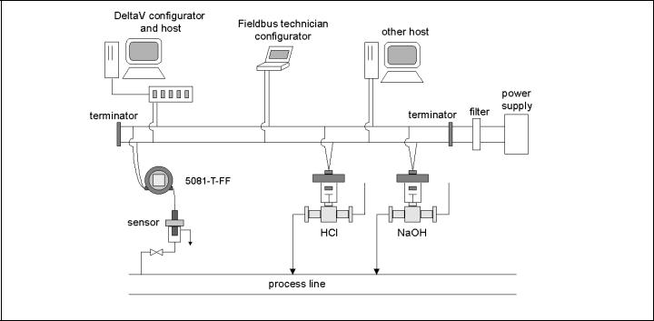
Figure 1-4 shows a 5081-T-FF being used to measure conductivity. The figure also shows three ways in which Fieldbus communication can be used to read process variables and configure the transmitter.
FIGURE 1-4. CONFIGURING MODEL 5081-T TRANSMITTER WITH FOUNDATION FIELDBUS
1.8 ASSET MANAGEMENT SOLUTIONS
Asset Management Solutions (AMS) is software that helps plant personnel better monitor the performance of analytical instruments, pressure and temperature transmitters, and control valves. Continuous monitoring means maintenance personnel can anticipate equipment failures and plan preventative measures before costly breakdown maintenance is required.
AMS uses remote monitoring. The operator, sitting at a computer, can view measurement data, change program settings, read diagnostic and warning messages, and retrieve historical data from any HART-compatible device, including the Model 5081-T transmitter. Although AMS allows access to the basic functions of any HART compatible device, Rosemount Analytical has developed additional software for that allows access to all features of the Model 5081-T transmitter.
AMS can play a central role in plant quality assurance and quality control. Using AMS Audit Trail, plant operators can track calibration frequency and results as well as warnings and diagnostic messages. The information is available to Audit Trail whether calibrations were done using the infrared remote controller, the Model 375 HART communicator, or AMS software.
AMS operates in Windows 95. See Figure 1-5 for a sample screen. AMS communicates through a HART-compatible modem with any HART transmitters, including those from other manufacturers. AMS is also compatible with FOUNDATION™ Fieldbus, which allows future upgrades to Fieldbus instruments.
Rosemount Analytical AMS windows provide access to all transmitter measurement and configuration variables. The user can read raw data, final data, and program settings and can reconfigure the transmitter from anywhere in the plant.
6

MODEL 5081-T |
|
|
|
|
SECTION 1.0 |
||
|
|
|
|
|
DESCRIPTION AND SPECIFICATIONS |
||
|
|
|
|
|
|
|
|
|
|
|
|
|
|
|
|
|
|
|
|
|
|
|
|
|
|
|
|
|
|
|
|
|
|
|
|
|
|
|
|
|
|
|
|
|
|
|
|
FIGURE 1-5. AMS MAIN MENU TOOLS
7
MODEL 5081-T |
SECTION 2.0 |
|
INSTALLATION |
SECTION 2.0
INSTALLATION
2.1Unpacking and Inspection
2.2Orienting the Display Board
2.3Mechanical Installation
2.4Power Supply/Current Loop — Model 5081-T-HT
2.5Power Supply Wiring for Model 5081-T-FF/FI
2.1UNPACKING AND INSPECTION
Inspect the shipping container. If it is damaged, contact the shipper immediately for instructions. Save the box. If there is no apparent damage, remove the transmitter. Be sure all items shown on the packing list are present. If items are missing, immediately notify Rosemount Analytical.
Save the shipping container and packaging. They can be reused if it is later necessary to return the transmitter to the factory.
2.2 ORIENTING THE DISPLAY BOARD
The display board can be rotated 90 degrees, clockwise or counterclockwise, from the original position. To reposition the display:
1.Loosen the cover lock nut until the tab disengages from the circuit end cap. Unscrew the cap.
2.Remove the three bolts holding the circuit board stack.
3.Lift and rotate the display board 90 degrees, clockwise or counterclockwise, into the desired position.
4.Position the display board on the stand offs. Replace and tighten the bolts.
5.Replace the circuit end cap.
2.3 MECHANICAL INSTALLATION
2.3.1 General information
1.The transmitter tolerates harsh environments. For best results, install the transmitter in an area where temperature extremes, vibrations, and electromagnetic and radio frequency interference are minimized or absent.
2.To prevent unintentional exposure of the transmitter circuitry to the plant environment, keep the security lock in place over the circuit end cap. To remove the circuit end cap, loosen the lock nut until the tab disengages from the end cap, then unscrew the cover.
3.The transmitter has two 3/4-inch conduit openings, one on each side of the housing. Run sensor cable through the left side opening (as viewed from the wiring terminal end of the transmitter) and run power wiring through the right side opening.
4.Use weathertight cable glands to keep moisture out of the transmitter.
5.If conduit is used, plug and seal the connections at the transmitter housing to prevent moisture from getting inside the transmitter.
NOTE
Moisture accumulating in the transmitter housing can affect the performance of the transmitter and may void the warranty.
6.If the transmitter is installed some distance from the sensor, a remote junction box with preamplifier in the junction box or in the sensor may be necessary. Consult the sensor instruction manual for maximum cable lengths.
8
MODEL 5081-T |
SECTION 2.0 |
INSTALLATION
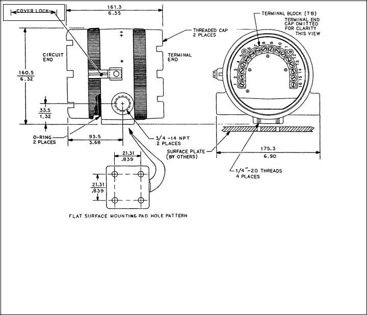
2.3.2 Mounting on a Flat Surface.
See Figure 2-1.
MILLIMETER |
INCH |
FIGURE 2-1. Mounting the Model 5081-T Toroidal Conductivity Transmitter on a Flat Surface
9
MODEL 5081-T |
SECTION 2.0 |
INSTALLATION
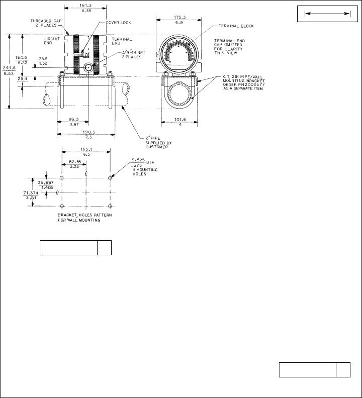
2.3.3 Pipe Mounting.
See Figure 2-2. The pipe mounting kit (PN 2002577) accommodates 1-1/2 to 2 in. pipe.
MILLIMETER |
INCH |
DWG. NO. |
REV. |
40308104 G
DWG. NO. |
REV. |
40308103 C
FIGURE 2-2. Using the Pipe Mounting Kit to Attach the Model 5081-T Conductivity Transmitter to a Pipe
10

MODEL 5081-T |
SECTION 2.0 |
|
INSTALLATION |
2.3.4 Inductive Loops.
The Model 5081-T conductivity transmitter is designed to make accurate measurements while in contact with the process stream. Measurements can also be tailored to high temperature and/or high pressure streams.
2.3.5 Sensor Selection.
All Rosemount Analytical contacting conductivity sensors with PT100 RTD or PT1000 RTD are compatible with the Model 5081-T transmitter. Please refer to Figures 3-5 thru 3-7 for appropriate sensor to transmitter wiring. The sensor cable should be routed through the left inlet closest to the connector.
Choose an inductive conductivity sensor that is appropriate for your process conditions and range of conductivity measurement.
TABLE 2-1. Model 5081-T Sensor Selection
RECOMMENDED RANGES FOR TOROIDAL SENSORS
|
Conductivity Sensor |
|
|
|
|
|
|
|
Model Number |
226 |
228 |
225 |
222 (1in.) |
222 (2 in.) |
242 |
|
|
|
|
|
|
|
|
|
Nominal Cell Constant |
1.0 |
3.0 |
3.0 |
6.0 |
4.0 |
* |
|
Min. Conductivity (µS/cm) |
50 |
200 |
200 |
500 |
500 |
100* |
|
|
|
|
|
|
|
|
|
Max. Conductivity (µS/cm) |
1,000,000 |
2,000,000 |
2,000,000 |
2,000,000 |
2,000,000 |
2,000,000* |
|
|
|
|
|
|
|
|
* Model 242 values depend on sensor configuration and wiring.
NOTE: Values shown are for 25°C conductivity with a temperature slope of 2% per degree C. The maximum range value will be lower for solutions with a higher temperature slope. Minimum conductivity depends on sensor.
RECOMMENDED SENSORS:
Model 222 Flow-Through
Model 225 Clean-In-Place (CIP)
Model 226 Submersion/
Insertion
Model 228 Submersion/
Insertion/
Retractable
Model 242 Flow-Through*
*Model 242-06 or 242-08 with 5081T do not have Intrinsically Safe approvals.
11

MODEL 5081-T |
SECTION 2.0 |
|
INSTALLATION |
2.4POWER SUPPLY/CURRENT LOOP
— MODEL 5081-T-HT
2.4.1 Power Supply and Load Requirements.
Refer to Figure 2-3.
The minimum power supply voltage is 12.5 Vdc and the maximum is 42.4 Vdc. The top line on the graph gives the voltage required to maintain at least 12.5 Vdc at the transmitter terminals when the output signal is 22 mA. The lower line is the supply voltage required to maintain a 30 Vdc terminal voltage when the output signal is 22 mA.
The power supply must provide a surge current during the first 80 milliseconds of start-up. For a 24 Vdc power supply and a 250 ohm load resistor the surge
current is 40 mA. For all other supply voltage and
resistance combinations the surge current is not FIGURE 2-3. Load/Power Supply Requirements expected to exceed 70 mA.
For digital (HART or AMS) communications, the load must be at least 250 ohms. To supply the 12.5 Vdc lift off voltage at the transmitter, the power supply voltage must be at least 18 Vdc.
For intrinsically safe operation the supply voltage should not exceed 30.0 Vdc.
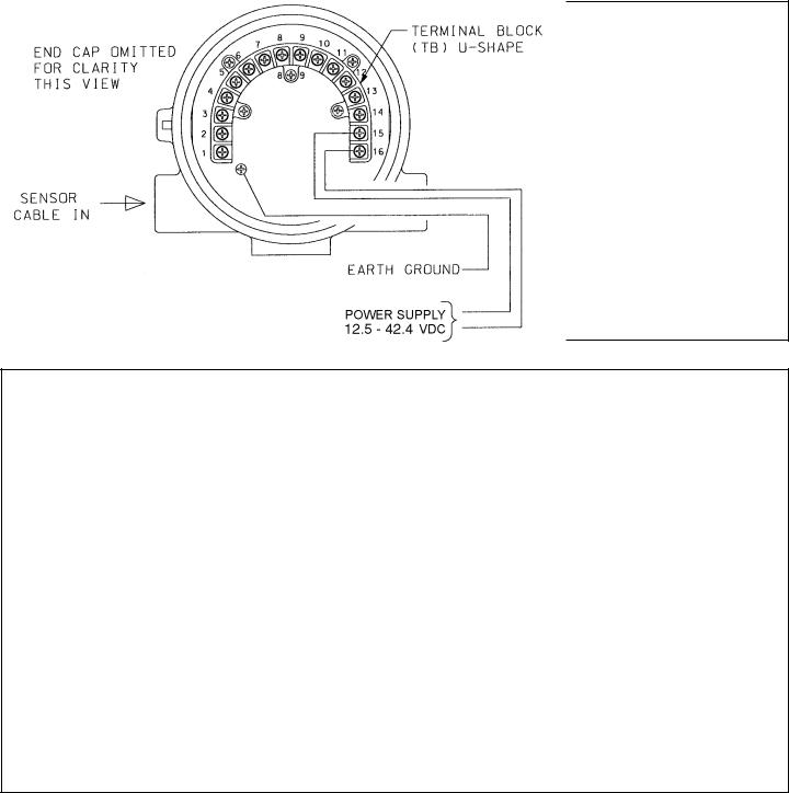
2.4.2 Power Supply-Current Loop Wiring.
Run the power/signal wiring through the opening nearest terminals 15 and 16. Use shielded cable and ground the shield at the power supply. To ground the transmitter, attach the shield to the grounding screw on the inside of the transmitter case. A third wire can also be used to connect the transmitter case to earth ground.
NOTE
For optimum EMI/RFI immunity, the power supply/output cable should be shielded and enclosed in an earthgrounded metal conduit.
Do not run power supply/signal wiring in the same conduit or cable tray with AC power lines or with relay actuated signal cables. Keep power supply/ signal wiring at least 6 ft (2 m) away from heavy electrical equipment.
An additional 0-1 mA current loop is available between TB-14 and TB-15. A 1 mA current in this loop signifies a sensor fault. See Section 3.0 for wiring instructions. See Section 8.4 or 10.6 and Section 12.0 for more information about sensor faults.
Refer to Figure 2-4.
FIGURE 2-4. Model 5081-T-HT Power Wiring Details
12
MODEL 5081-T
2.5POWER SUPPLY WIRING FOR MODEL 5081-T-FF/FI
2.5.1 Power Supply Wiring. Refer to Figure 2-5 and Figure 2-6.
Run the power/signal wiring through the opening nearest terminals 15 and 16. Use shielded cable and ground the shield at the power supply. To ground the transmitter, attach the shield to the grounding screw on the inside of the transmitter case. A third wire can also be used to connect the transmitter case to earth ground.
NOTE
For optimum EMI/RFI immunity, the power supply/output cable should be shielded and enclosed in an earth-grounded metal conduit.
Do not run power supply/signal wiring in the same conduit or cable tray with AC power lines or with relay actuated signal cables. Keep power supply/signal wiring at least 6 ft (2 m) away from heavy electrical equipment.
SECTION 2.0
INSTALLATION
5081-T |
|
5081-T |
Transmitter |
|
Transmitter |
|
|
|
FIGURE 2-5. Typical Fieldbus Network Electrical
Wiring Configuration
9 - 32
FIGURE 2-6. Model 5081-T-FF Power Wiring Details
13
MODEL 5081-T |
SECTION 3.0 |
|
WIRING |
SECTION 3.0
WIRING
3.1Sensor Wiring
3.2Electrical Installation
3.1 SENSOR WIRING
Wire sensor as shown below in Figure 3-1. Keep sensor wiring separate from power wiring. For best EMI/RFI protection, use shielded output signal cable in an earth-grounded metal conduit. Refer to the sensor instruction manual for more details.
FIGURE 3-1. Wiring Model 5081T-HT
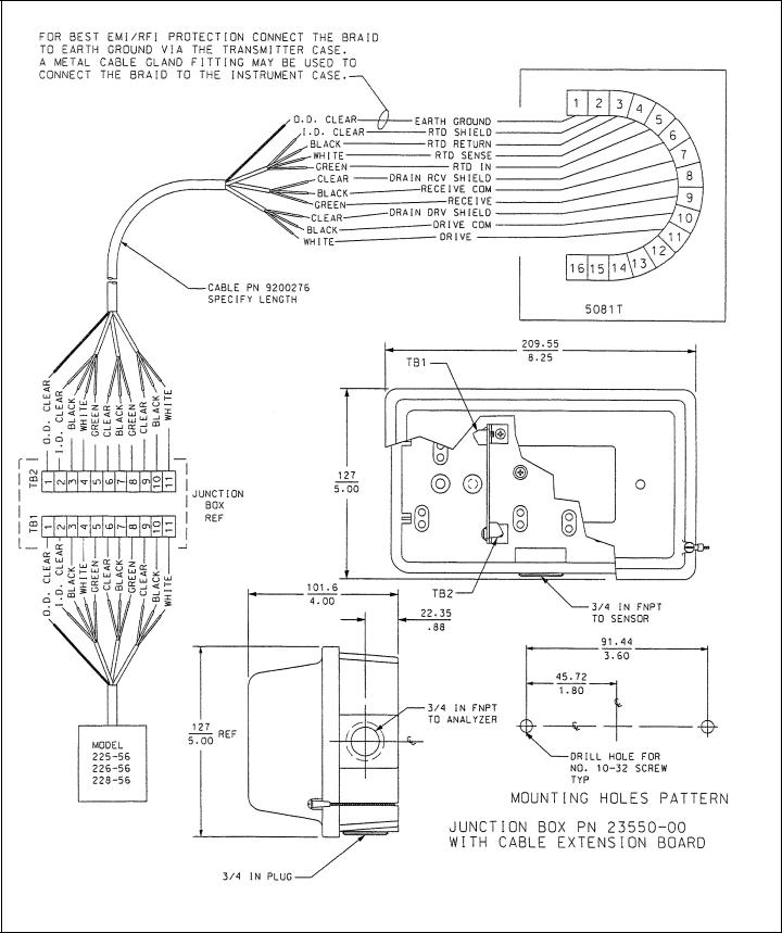
3.1.1 WIRING THROUGH A JUNCTION BOX
The sensor can be wired to the analyzer through a remote junction box (PN 23550-00). Wire the extension cable and sensor cable point-to-point. Refer to the sensor instruction manual for more details.
Factory-terminated (PN 23294-05) and unterminated (PN 9200276) connecting cable are available. The use of factory-termi- nated cable is strongly recommended. To prepare unterminated cable for use, follow the instructions in the sensor instruction manual.
For maximum EMI/RFI protection, the outer braid of the sensor cable should be connected to the outer braided shield of the extension cable. At the instrument, connect the outer braid of the extension cable to earth ground.
14
MODEL 5081-T
3.1.2 POWER WIRING MODEL 5081-T-HT
For general purpose areas, wire power as shown in Figure 3-2. For hazardous areas, please see hazardous area installation drawings.
SECTION 3.0
WIRING
FIGURE 3-2. Power Supply/Current Loop Wiring for Model 5081-T-HT
3.1.3 POWER WIRING MODEL 5081-T-FF
For general purpose areas, wire power as shown in Figure 3-3. For hazardous areas, please see hazardous area installation drawings.
9 - 32
FIGURE 3-3. Power Supply/Current Loop Wiring for Model 5081-T-FF
FIGURE 3-4. Power Supply and Sensor Wiring for Model 5081-T
15
MODEL 5081-T |
SECTION 3.0 |
|
WIRING |
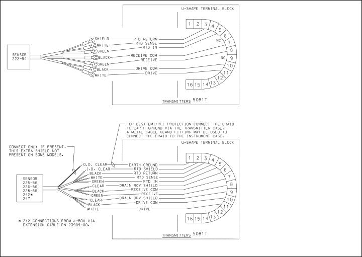
3.2 ELECTRICAL INSTALLATION
All Rosemount Analytical contacting conductivity sensors with PT100 RTD or PT1000 RTD are compatible with the Model 5081-T transmitter. Please refer to Figures 3-5 thru 3-7 for appropriate sensor to transmitter wiring. The sensor cable should be routed through the left inlet closest to the connector.
NOTE
Optimum EMI/RFI immunity may be achieved on sensors whose interconnecting cable has an outer braided shield by utilizing a cable gland fitting that provides for continuity between the braided shield and the transmitter enclosure. An equivalent conduit connector may also be used if the sensor cable is to be enclosed in conduit.
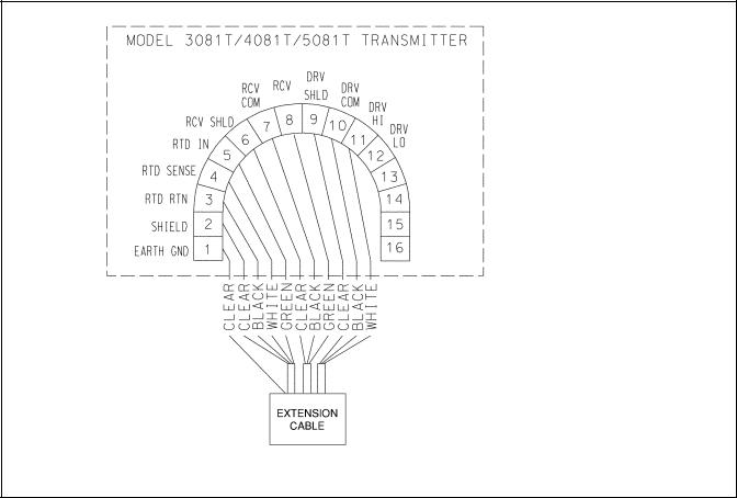
FIGURE 3-5. Wiring Model 242 sensor to Model 5081-T transmitter
16
MODEL 5081-T |
SECTION 3.0 |
|
WIRING |
FIGURE 3-6. Wiring Models 222, 225, 226, 228, 242, & 247 sensors to Model 5081-T transmitter
17
MODEL 5081-T |
SECTION 3.0 |
|
WIRING |
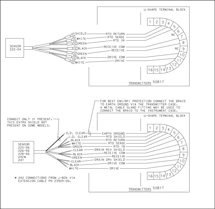
FIGURE 3-7. Wiring Models 222, 225, 226, & 228 sensors to Model 5081-T transmitter
18

MODEL 5081-T |
SECTION 4.0 |
|
INTRINSICALLY SAFE & EXPLOSION PROOF |
SECTION 4.0
INTRINSICALLY SAFE & EXPLOSION PROOF
IRC - INFRARED REMOTE CONTROL
REMOTE CONTROL |
LR 34186 |
|
SUBSTITUTION OF |
|
IS/I/1/A,B,C & D |
YEAR |
|
Exia |
|
COMPONENTS MAY |
|
NI/I/2/A,B,C & D |
|
||
|
|
|
|
||||
INTRINSICALLY SAFE EQUIPMENT |
|
IMPAIR INTRINSIC SAFETY |
|
T4 Tamb = 40°C |
|
||
HAZARDOUS AREA LOCATIONS: |
|
PN 23572-00 |
|
T3A Tamb = 80°C |
|
|
|
|
|
|
|
|
|||
CLASS I, DIV 1, GP A, B, C, D |
|
|
|
|
|
||
|
|
|
Baseefa02ATEX0198 |
|
|
||
CLASS I, DIV 2, GP A, B, C, D |
|
WARNING: |
|
|
|
||
|
|
II 1G EExia IIC T4 |
1180 |
|
|||
T3C Tamb = 40°C T3 Tamb = 80°C |
|
|
|
||||
|
TO PREVENT IGNITION |
|
|
||||
|
|
1.5Vdc AAA BATTERIES |
|
||||
1.5Vdc AAA BATTERIES |
|
|
CHANGE BATTERIES IN |
|
EVEREADY E92/1212 |
|
|
EVEREADY E92/1212 |
|
|
A NONHAZARDOUS AREA |
|
DURACELL MN2400/PC2400 |
|
|
DURACELL MN2400/PC2400 |
|
ONLY |
|
ROSEMOUNT ANALYTICAL 92606 USA |
|||
|
|
|
|
|
|
|
|
FIGURE 4-1. Model 5081-T-HT Infrared Remote Control — CSA, FM, & Baseefa/ATEX approvals
IRC - INFRARED REMOTE CONTROL
REMOTE CONTROL |
LR 34186 |
|
SUBSTITUTION OF |
|
IS/I/1/A,B,C & D |
YEAR |
|
Exia |
|
COMPONENTS MAY |
|
NI/I/2/A,B,C & D |
|
||
|
|
|
|
||||
INTRINSICALLY SAFE EQUIPMENT |
|
IMPAIR INTRINSIC SAFETY |
|
T4 Tamb = 40°C |
|
||
HAZARDOUS AREA LOCATIONS: |
|
PN 23572-00 |
|
T3A Tamb = 80°C |
|
|
|
|
|
|
|
|
|||
CLASS I, DIV 1, GP A, B, C, D |
|
|
|
|
|
||
|
|
|
Baseefa02ATEX0198 |
|
|
||
CLASS I, DIV 2, GP A, B, C, D |
|
WARNING: |
|
|
|
||
|
|
II 1G EExia IIC T4 |
1180 |
|
|||
T3C Tamb = 40°C T3 Tamb = 80°C |
|
|
|
||||
|
TO PREVENT IGNITION |
|
1.5Vdc AAA BATTERIES |
|
|||
1.5Vdc AAA BATTERIES |
|
|
CHANGE BATTERIES IN |
|
EVEREADY E92/1212 |
|
|
EVEREADY E92/1212 |
|
|
A NONHAZARDOUS AREA |
|
DURACELL MN2400/PC2400 |
|
|
DURACELL MN2400/PC2400 |
|
ONLY |
|
ROSEMOUNT ANALYTICAL 92606 USA |
|||
|
|
|
|
|
|
|
|
FIGURE 4-2. Model 5081-T-FF/FI Infrared Remote Control — CSA, FM, & Baseefa/ATEX approvals
19

MODEL 5081-T |
SECTION 4.0 |
|
INTRINSICALLY SAFE & EXPLOSION PROOF |
4.1 INTRINSICALLY SAFE AND EXPLOSION-PROOF INSTALLATION FOR MODEL 5081-T-HT
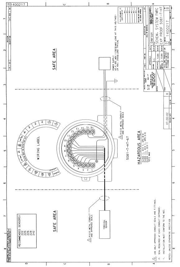 FIGURE 4-3. FM Explosion-Proof Installation for Model 5081-T-HT
20
MODEL 5081-T |
SECTION 4.0 |
|
INTRINSICALLY SAFE & EXPLOSION PROOF |
FIGURE 4-4. FM Intrinsically Safe Installation for Model 5081-T-HT
21

MODEL 5081-T |
SECTION 4.0 |
|
INTRINSICALLY SAFE & EXPLOSION PROOF |
FIGURE 4-5. CSA Intrinsically Safe Installation for Model 5081-T-HT
22
MODEL 5081-T |
SECTION 4.0 |
|
INTRINSICALLY SAFE & EXPLOSION PROOF |
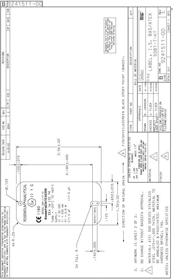
FIGURE 4-6. ATEX Intrisically Safe Label for Model 5081-T-HT
23
MODEL 5081-T |
SECTION 4.0 |
|
INTRINSICALLY SAFE & EXPLOSION PROOF |
FIGURE 4-7. ATEX Intrisically Safe Label for Model 5081-T-HT
24
 Loading...