


 Loading...
System Reference Manual
2-3-9000-744, Rev G
September 2014
700XA Gas Chromatograph
Applies to the Rosemount® Analytical 700XA Gas Chromatograph and the Danalyzer™ 700XA Gas Chromatograph
NOTICE
ROSEMOUNT ANALYTICAL, INC. (“SELLER”) SHALL NOT BE LIABLE FOR TECHNICAL OR EDITORIAL ERRORS IN THIS MANUAL OR OMISSIONS FROM THIS MANUAL. SELLER MAKES NO WARRANTIES, EXPRESSED OR IMPLIED, INCLUDING THE IMPLIED WARRANTIES OF MERCHANTABILITY AND FITNESS FOR A PARTICULAR PURPOSE WITH RESPECT TO THIS MANUAL AND, IN NO EVENT, SHALL SELLER BE LIABLE FOR ANY SPECIAL OR CONSEQUENTIAL DAMAGES INCLUDING, BUT NOT LIMITED TO, LOSS OF PRODUCTION, LOSS OF PROFITS, ETC.
PRODUCT NAMES USED HEREIN ARE FOR MANUFACTURER OR SUPPLIER IDENTIFICATION ONLY AND MAY BE TRADEMARKS/ REGISTERED TRADEMARKS OF THESE COMPANIES.
THE CONTENTS OF THIS PUBLICATION ARE PRESENTED FOR INFORMATIONAL PURPOSES ONLY, AND WHILE EVERY EFFORT HAS BEEN MADE TO ENSURE THEIR ACCURACY, THEY ARE NOT TO BE CONSTRUED AS WARRANTIES OR GUARANTEES, EXPRESSED OR IMPLIED, REGARDING THE PRODUCTS OR SERVICES DESCRIBED HEREIN OR THEIR USE OR APPLICABILITY. WE RESERVE THE RIGHT TO MODIFY OR IMPROVE THE DESIGNS OR SPECIFICATIONS OF SUCH PRODUCTS AT ANY TIME.
SELLER DOES NOT ASSUME RESPONSIBILITY FOR THE SELECTION, USE OR MAINTENANCE OF ANY PRODUCT. RESPONSIBILITY FOR PROPER SELECTION, USE AND MAINTENANCE OF ANY SELLER PRODUCT REMAINS SOLELY WITH THE PURCHASER AND END-USER.
ROSEMOUNT AND THE ROSEMOUNT ANALYTICAL LOGO ARE REGISTERED TRADEMARKS OF ROSEMOUNT ANALYTICAL. THE EMERSON LOGO IS A TRADEMARK AND SERVICE MARK OF EMERSON ELECTRIC CO.
©2014
ROSEMOUNT ANALYTICAL INC.
HOUSTON, TX
USA
All rights reserved. No part of this work may be reproduced or copied in any form or by any means—graphic, electronic, or mechanical—without first receiving the written permission of Rosemount Analytical Inc., Houston, Texas, U.S.A.
Warranty
1.LIMITED WARRANTY: Subject to the limitations contained in Section 2 herein and except as otherwise expressly provided herein, Rosemount Analytical, Inc. (“Seller”) warrants that the firmware will execute the programming instructions provided by Seller, and that the Goods manufactured or Services provided by Seller will be free from defects in materials or workmanship under normal use and care until the expiration of the applicable warranty period. Goods are warranted for twelve (12) months from the date of initial installation or eighteen (18) months from the date of shipment by Seller, whichever period expires first. Consumables and Services are warranted for a period of 90 days from the date of shipment or completion of the Services. Products purchased by Seller from a third party for resale to Buyer (“Resale Products”) shall carry only the warranty extended by the original manufacturer. Buyer agrees that Seller has no liability for Resale Products beyond making a reasonable commercial effort to arrange for procurement and shipping of the Resale Products. If Buyer discovers any warranty defects and notifies Seller thereof in writing during the applicable warranty period, Seller shall, at its option, promptly correct any errors that are found by Seller in the firmware or Services, or repair or replace F.O.B. point of manufacture that portion of the Goods or firmware found by Seller to be defective, or refund the purchase price of the defective portion of the Goods/Services. All replacements or repairs necessitated by inadequate maintenance, normal wear and usage, unsuitable power sources, unsuitable environmental conditions, accident, misuse, improper installation, modification, repair, storage or handling, or any other cause not the fault of Seller are not covered by this limited warranty, and shall be at Buyer's expense. Seller shall not be obligated to pay any costs or charges incurred by Buyer or any other party except as may be agreed upon in writing in advance by an authorized Seller representative. All costs of dismantling, reinstallation and freight and the time and expenses of Seller's personnel for site travel and diagnosis under this warranty clause shall be borne by Buyer unless accepted in writing by Seller. Goods repaired and parts replaced during the warranty period shall be in warranty for the remainder of the original warranty period or ninety (90) days, whichever is longer. This limited warranty is the only warranty made by Seller and can be amended only in a writing signed by an authorized representative of Seller. Except as otherwise expressly provided in the Agreement, THERE ARE NO REPRESENTATIONS OR WARRANTIES OF ANY KIND, EXPRESSED OR IMPLIED, AS TO MERCHANTABILITY, FITNESS FOR PARTICULAR PURPOSE, OR ANY OTHER MATTER WITH RESPECT TO ANY OF THE GOODS OR SERVICES. It is understood that corrosion or erosion of materials is not covered by our guarantee.
2.LIMITATION OF REMEDY AND LIABILITY: SELLER SHALL NOT BE LIABLE FOR DAMAGES CAUSED BY DELAY IN PERFORMANCE. THE SOLE AND EXCLUSIVE REMEDY FOR BREACH OF WARRANTY HEREUNDER SHALL BE LIMITED TO REPAIR, CORRECTION, REPLACEMENT OR REFUND OF PURCHASE PRICE UNDER THE LIMITED WARRANTY CLAUSE IN SECTION 1 HEREIN. IN NO EVENT, REGARDLESS OF THE FORM OF THE CLAIM OR CAUSE OF ACTION (WHETHER BASED IN CONTRACT, INFRINGEMENT, NEGLIGENCE, STRICT LIABILITY, OTHER TORT OR OTHERWISE), SHALL SELLER'S LIABILITY TO BUYER AND/OR ITS CUSTOMERS EXCEED THE PRICE TO BUYER OF THE SPECIFIC GOODS MANUFACTURED OR SERVICES PROVIDED BY SELLER GIVING RISE TO THE CLAIM OR CAUSE OF ACTION. BUYER AGREES THAT IN NO EVENT SHALL SELLER'S LIABILITY TO BUYER AND/OR ITS CUSTOMERS EXTEND TO INCLUDE INCIDENTAL, CONSEQUENTIAL OR PUNITIVE DAMAGES. THE TERM “CONSEQUENTIAL DAMAGES” SHALL INCLUDE, BUT NOT BE LIMITED TO, LOSS OF ANTICIPATED PROFITS, LOSS OF USE, LOSS OF REVENUE AND COST OF CAPITAL.

Contents
Contents
Chapter 1 |
Introduction ................................................................................................................... |
|
1 |
|
|
1.1 |
Description of manual .................................................................................................................. |
1 |
|
|
1.2 |
System description ...................................................................................................................... |
1 |
|
|
|
1.2.1 |
Analyzer assembly ......................................................................................................... |
1 |
|
|
1.2.2 |
Electronics assembly ..................................................................................................... |
1 |
|
|
1.2.3 |
Sample conditioning system (SCS) ................................................................................ |
2 |
|
1.3 |
Functional description ................................................................................................................. |
2 |
|
|
1.4 |
Software description .................................................................................................................... |
3 |
|
|
|
1.4.1 |
Embedded GC firmware ................................................................................................ |
3 |
|
|
1.4.2 |
MON2020 ..................................................................................................................... |
4 |
|
1.5 |
Theory of operation ..................................................................................................................... |
5 |
|
|
|
1.5.1 |
Thermal conductivity detector ...................................................................................... |
5 |
|
|
1.5.2 |
Flame ionization detector .............................................................................................. |
7 |
|
|
1.5.3 |
Liquid sample injection valve ......................................................................................... |
7 |
|
|
1.5.4 |
Methanator ................................................................................................................... |
8 |
|
|
1.5.5 |
Data acquisition ............................................................................................................ |
9 |
|
|
1.5.6 |
Peak detection .............................................................................................................. |
9 |
|
1.6 |
Basic analysis computations ....................................................................................................... |
10 |
|
|
|
1.6.1 |
Concentration analysis - response factor ..................................................................... |
10 |
|
|
1.6.2 |
Concentration calculation - mole percentage (without normalization) ........................ |
11 |
|
|
1.6.3 |
Concentration calculation in mole percentage (with normalization) ........................... |
12 |
|
1.7 |
Glossary |
..................................................................................................................................... |
12 |
Chapter 2 |
Equipment description and specifications .................................................................... |
15 |
||
|
2.1 |
Equipment description .............................................................................................................. |
15 |
|
|
|
2.1.1 |
Front panel assembly .................................................................................................. |
15 |
|
|
2.1.2 |
Upper compartment ................................................................................................... |
19 |
|
|
2.1.3 |
Lower compartment ................................................................................................... |
19 |
|
|
2.1.4 |
Mechanical pressure regulators ................................................................................... |
20 |
|
2.2 |
Equipment specifications ........................................................................................................... |
21 |
|
|
|
2.2.1 |
Utilities ........................................................................................................................ |
21 |
|
|
2.2.2 |
Electronic hardware .................................................................................................... |
22 |
|
|
2.2.3 |
Airless analytical oven ................................................................................................. |
23 |
|
|
2.2.4 |
Software ..................................................................................................................... |
23 |
|
|
2.2.5 |
Corrosion protection ................................................................................................... |
24 |
|
|
2.2.6 |
Archived Data Storage Capabilities .............................................................................. |
24 |
Chapter 3 |
Installation and setup ................................................................................................... |
27 |
||
|
3.1 |
Precautions and warnings .......................................................................................................... |
27 |
|
|
|
3.1.1 |
Installation considerations .......................................................................................... |
29 |
|
3.2 |
XA mounting arrangements ...................................................................................................... |
29 |
|
|
|
3.2.1 |
Wall mount ................................................................................................................. |
30 |
|
|
3.2.2 |
Pole mount ................................................................................................................. |
31 |
|
|
3.2.3 |
Floor mount ................................................................................................................ |
32 |
|
3.3 |
Gas chromatograph wiring ........................................................................................................ |
33 |
|
|
|
3.3.1 |
Power source wiring .................................................................................................... |
33 |
|
|
3.3.2 |
Signal wiring ............................................................................................................... |
33 |
i

Contents
|
|
3.3.3 |
Electrical and signal ground ......................................................................................... |
34 |
|
|
3.3.4 |
Electrical conduit ......................................................................................................... |
35 |
|
|
3.3.5 |
Sample system requirements ...................................................................................... |
36 |
|
3.4 |
Preparation ................................................................................................................................ |
37 |
|
|
|
3.4.1 |
Site selection ............................................................................................................... |
37 |
|
|
3.4.2 |
Unpacking the unit ...................................................................................................... |
37 |
|
|
3.4.3 |
Required tools and components .................................................................................. |
38 |
|
|
3.4.4 |
Supporting tools and components .............................................................................. |
39 |
|
3.5 |
Installation ................................................................................................................................. |
39 |
|
|
|
3.5.1 |
DC power supply ......................................................................................................... |
39 |
|
|
3.5.2 |
Optional AC/DC power converter ................................................................................ |
41 |
|
|
3.5.3 |
Connect the sample and other gas lines ...................................................................... |
42 |
|
|
3.5.4 |
Maximum effective distance by communication protocol type ................................... |
45 |
|
|
3.5.5 |
RS-485 serial port terminals ........................................................................................ |
45 |
|
|
3.5.6 |
Installing and connecting to an analog modem card ................................................... |
45 |
|
|
3.5.7 |
Connecting to the GC via the analog modem .............................................................. |
46 |
|
|
3.5.8 |
Connecting directly to a PC using the GC’s Ethernet port ............................................ |
47 |
|
|
3.5.9 |
Troubleshooting DHCP connectivity issues ................................................................. |
50 |
|
|
3.5.10 |
Connecting directly to a PC using the GC’s serial port .................................................. |
51 |
|
|
3.5.11 |
Connecting directly to a PC using the GC’s wired Ethernet terminal ............................ |
53 |
|
|
3.5.12 |
Assigning a static IP address to the GC ......................................................................... |
55 |
|
|
3.5.13 |
Discrete digital I/O wiring ............................................................................................ |
57 |
|
|
3.5.14 |
Analog input wiring ..................................................................................................... |
63 |
|
|
3.5.15 |
Analog output wiring .................................................................................................. |
67 |
|
3.6 |
Leak checking and purging for first calibration ........................................................................... |
72 |
|
|
|
3.6.1 |
Checking the GC for leaks ............................................................................................ |
72 |
|
|
3.6.2 |
Purging carrier gas lines .............................................................................................. |
73 |
|
|
3.6.3 |
Purging calibration gas lines ........................................................................................ |
74 |
|
3.7 |
System startup .......................................................................................................................... |
74 |
|
Chapter 4 |
Operation and maintenance ......................................................................................... |
75 |
||
|
4.1 |
Warning and precautions ........................................................................................................... |
75 |
|
|
4.2 |
Start a two-point calibration ...................................................................................................... |
75 |
|
|
4.3 |
Troubleshooting and repair concept .......................................................................................... |
76 |
|
|
4.4 |
Routine maintenance ................................................................................................................ |
76 |
|
|
|
4.4.1 |
Maintenance checklist ................................................................................................. |
76 |
|
|
4.4.2 |
Routine maintenance procedures ............................................................................... |
78 |
|
|
4.4.3 |
Precautions for handling PC assemblies ....................................................................... |
78 |
|
|
4.4.4 |
General troubleshooting ............................................................................................. |
78 |
|
|
4.4.5 |
Checking the GC for leaks ............................................................................................ |
89 |
|
|
4.4.6 |
Valves ......................................................................................................................... |
90 |
|
|
4.4.7 |
Detector maintenance ................................................................................................ |
93 |
|
|
4.4.8 |
Removing the FID ........................................................................................................ |
95 |
|
|
4.4.9 |
LSIV maintenance ....................................................................................................... |
97 |
|
|
4.4.10 |
Methanator maintenance .......................................................................................... |
103 |
|
|
4.4.11 |
Measure vent flow ..................................................................................................... |
105 |
|
|
4.4.12 |
Electrical components ............................................................................................... |
105 |
|
|
4.4.13 |
Factory settings for jumpers and switches ................................................................. |
110 |
|
|
4.4.14 |
Communications ....................................................................................................... |
111 |
|
|
4.4.15 |
Installing or replacing a FOUNDATION fieldbus module ............................................ |
119 |
|
|
4.4.16 |
Analog inputs and outputs ........................................................................................ |
126 |
|
|
4.4.17 |
Discrete digital inputs and outputs ............................................................................ |
126 |
ii
|
|
|
|
Contents |
|
|
|
|
|
|
|
4.4.18 |
Recommended spare parts ....................................................................................... |
127 |
|
|
4.4.19 |
Upgrading the embedded software ........................................................................... |
127 |
Appendices and reference |
|
|||
Appendix A |
Local operator interface ............................................................................................. |
129 |
||
|
A.1 |
Interface components for displaying and entering data ........................................................... |
129 |
|
|
|
A.1.1 |
Light emitting diode indicators ................................................................................. |
129 |
|
|
A.1.2 |
LCD screen ................................................................................................................ |
130 |
|
|
A.1.3 |
Keypad ...................................................................................................................... |
130 |
|
A.2 |
Using the local operator interface ............................................................................................ |
131 |
|
|
|
A.2.1 |
Start up ..................................................................................................................... |
131 |
|
|
A.2.2 |
Navigating menus ..................................................................................................... |
132 |
|
|
A.2.3 |
Navigating the screen ............................................................................................... |
132 |
|
|
A.2.4 |
Editing numeric fields ................................................................................................ |
134 |
|
|
A.2.5 |
Editing non-numeric fields ........................................................................................ |
135 |
|
A.3 |
Screen navigation and interaction tutorial ............................................................................... |
139 |
|
|
A.4 |
The LOI screens ........................................................................................................................ |
145 |
|
|
|
A.4.1 |
The Chromatogram menu ......................................................................................... |
147 |
|
|
A.4.2 |
The Hardware menu .................................................................................................. |
152 |
|
|
A.4.3 |
The Application menu ............................................................................................... |
157 |
|
|
A.4.4 |
The Logs/Reports menu ............................................................................................ |
162 |
|
|
A.4.5 |
The Control menu ..................................................................................................... |
166 |
|
|
A.4.6 |
The Manage menu .................................................................................................... |
170 |
|
A.5 |
Troubleshooting a blank LOI screen ......................................................................................... |
172 |
|
Appendix B |
Carrier gas installation and maintenance .................................................................... |
175 |
||
|
B.1 |
Carrier gas ............................................................................................................................... |
175 |
|
|
B.2 |
Installation and line purging .................................................................................................... |
176 |
|
|
B.3 |
Replacing carrier cylinder ......................................................................................................... |
177 |
|
|
B.4 |
Calibration gas ......................................................................................................................... |
177 |
|
Appendix C |
Recommended spare parts ......................................................................................... |
179 |
||
|
C.1 |
Recommended spare parts for 700XA TCD analyzers ............................................................... |
179 |
|
|
C.2 |
Recommended spare parts for 700XA FID/TCD analyzers ........................................................ |
180 |
|
|
C.3 |
Recommended spare parts for 700XA FID analyzers ................................................................ |
181 |
|
Appendix D |
Shipping and long-term storage recommendations .................................................... |
183 |
||
Appendix E |
Engineering drawings ................................................................................................ |
185 |
||
|
E.1 |
List of engineering drawings .................................................................................................... |
185 |
|
iii

Contents
iv

Introduction
1 Introduction
This section describes the contents and purpose of the 700XA Gas Chromatograph System Reference Manual, a description of the Model 700XA system, an explanation of the theory of operation, and a glossary of chromatograph terminology.
Use this section to get acquainted with the basic engineering of the 700XA.
1.1Description of manual
The 700XA Gas Chromatograph System Reference Manual (P/N 3-9000-744) consists of installation, operations, maintenance, and troubleshooting procedures.
1.2System description
The 700XA is a high-speed gas chromatograph (GC) system that is engineered to meet specific field application requirements based on typical hydrocarbon stream composition and anticipated concentration of the selected components. In its standard configuration, the 700XA gas chromatograph can handle up to eight streams: seven for sample streams and one calibration stream.
The 700XA system consists of two major parts: the analyzer assembly and the electronics assembly. Depending upon the particular GC, there may also be a third, optional, assembly called the sample conditioning system (SCS).
The 700XA’s electronics and hardware are housed in an explosion-proof enclosure that meets the approval guidelines of various certification agencies for use in hazardous environments. See the certification tag on the GC for specific details about agency approvals.
1.2.1Analyzer assembly
The analyzer assembly includes the columns, TCDs/FIDs, a preamplifier, a preamplifier power supply, stream switching valves, analytical valves and solenoids. Additionally, the 700XA can be equipped with a liquid sample injection valve or a methanator.
For more information, see Section 2.1.2.
1.2.2Electronics assembly
The electronics assembly includes the electronics and ports necessary for signal processing, instrument control, data storage, personal computer (PC) interface, and telecommunications. This assembly allows the user to use MON2020 to control the GC. Refer to Section 2.2.2 for more details.
1 Introduction
1

Introduction
The GC-to-PC interface provides the user with the greatest capability, ease-of-use, and flexibility. MON2020 can be used to edit applications, monitor operations, calibrate streams, and display analysis chromatograms and reports, which can then be stored as files on the PC’s hard drive or printed from a printer connected to the PC.
 WARNING!
Do not use a PC or a printer in a hazardous area. Serial ports and Modbus communication links are provided to connect the unit to the PC and to connect to other computers and printers in a safe area. Failure to follow this warning may result in injury or death to personnel or cause damage to the equipment.
1.2.3Sample conditioning system (SCS)
The optional sample conditioning system is located between the process stream and the sample inlet, which is often mounted below the GC. The standard SCS configuration includes a stream switching system and filters.
1.3Functional description
A sample of the gas to be analyzed is taken from the process stream by a sample probe installed in the process line. The sample passes through a sample line to the SCS where it is filtered or otherwise conditioned. After conditioning, the sample flows to the Analyzer Assembly for separation and detection of the gas components.
The chromatographic separation of the sample gas into its components is accomplished in the following manner. A precise volume of sample gas is injected into one of the analytical columns. The column contains a stationary phase (packing) that is either an active solid or an inert solid support that is coated with a liquid phase (absorption partitioning). The sample gas is moved through the column by means of a mobile phase (carrier gas). The selective retardation of the components takes place in the column, causing each component to move through the column at a different rate. This separates the sample into its constituent gases and vapors.
A detector located at the outlet of the analytical column senses the elution of components from the column and produces electrical outputs proportional to the concentration of each component.
Note
For additional information, see Section 1.4.
Output from the electronic assembly is normally displayed on a remotely located PC or a printer. Connection between the GC and the PC can be accomplished via a direct serial line, an optional ethernet cable, or via a Modbus-compatible communication interface.
Several chromatograms may be displayed via MON2020, with separate color schemes, allowing the user to compare present and past data.
2
Introduction
In most cases it is essential to use MON2020 to configure and troubleshoot the GC. The PC may be remotely connected via ethernet, telephone, radio or satellite communications. Once installed and configured, the GC can operate independently for long periods of time.
Figure 1-1: Gas chromatography process model
1 Introduction
1.4Software description
The GC uses three distinct types of software. This enables total flexibility in defining the calculation sequence, printed report content, format, type and amount of data for viewing, control and/or transmission to another computer or controller assembly. The three types are:
•Embedded GC firmware
•Application configuration software
•Maintenance and operations software (MON2020)
The BOS and the Application configuration software are installed when the 700XA is shipped. The application configuration is tailored to the customer’s process and shipped on a CD-ROM. Note that the hardware and software are tested together as a unit before the equipment leaves the factory. MON2020 communicates with the GC and can be used to initiate site system setup (i.e., operational parameters, application modifications, and maintenance).
1.4.1Embedded GC firmware
The GC’s embedded firmware supervises operation of the 700XA through its internal microprocessor-based controller; all direct hardware interface is via this control software. It consists of a multi-tasking program that controls separate tasks in system operation, as well as hardware self-testing, user application downloading, start-up, and communications. Once configured, the 700XA can operate as a stand alone unit.
3

Introduction
1.4.2MON2020
MON2020 is a Windows-based program that allows the user to maintain, operate, and troubleshoot a gas chromatograph. Individual GC functions that can be initiated or controlled by MON2020 include, but are not limited to, the following:
•Valve activations
•Timing adjustments
•Stream sequences
•Calibrations
•Baseline runs
•Analyses
•Halt operation
•Stream/detector/heater assignments
•Stream/component table assignments
•Stream/calculation assignments
•Diagnostics
•Alarm and event processing
•Event sequence changes
•Component table adjustments
•Calculation adjustments
•Alarm parameters adjustments
•Analog scale adjustments
•LOI variable assignments (optional)
•Foundation Fieldbus variable assignments (optional)
Reports and logs that can be produced, depending upon the GC application in use, include, but are not limited to, the following:
•Configuration report
•Parameter list
•Analysis chromatogram
•Chromatogram comparison
•Alarm log (unacknowledged and active alarms)
•Event log
•Various analysis reports
For a complete list of the GC functions, reports, and logs available through MON2020, consult the software manual (P/N 2-3-9000-745).
MON2020 provides operator control of the 700XA, monitors analysis results, and inspects and edits various parameters that affect 700XA operation. It also controls display and printout of the chromatograms and reports, and it stops and starts automatic analysis cycling or calibration runs.
4

Introduction
After the equipment/software has been installed and the operation stabilized, automatic operation can be initiated via an ethernet network.
1.5Theory of operation
The following sections discuss the theory of operation for the GC, the engineering principles and the concepts used.
Note
See Section 1.7 for definitions of the terminology used in the following explanations.
1.5.1Thermal conductivity detector
One of the detectors available on the 700XA is a thermal conductivity detector (TCD) that consists of a balanced bridge network with heat sensitive thermistors in each leg of the bridge. Each thermistor is enclosed in a separate chamber of the detector block.
One thermistor is designated the reference element and the other thermistor is designated the measurement element. See Figure 1-2 for a schematic diagram of the thermal conductivity detector.
Figure 1-2: Analyzer assembly with TCD bridge
1 Introduction
5
Introduction
In the quiescent condition, prior to injecting a sample, both legs of the bridge are exposed to pure carrier gas. In this condition, the bridge is balanced and the bridge output is electrically nulled.
The analysis begins when the sample valve injects a fixed volume of sample into the column. The continuous flow of carrier gas moves the sample through the column. As successive components elute from the column, the temperature of the measurement element changes.
The temperature change unbalances the bridge and produces an electrical output proportional to the component concentration.
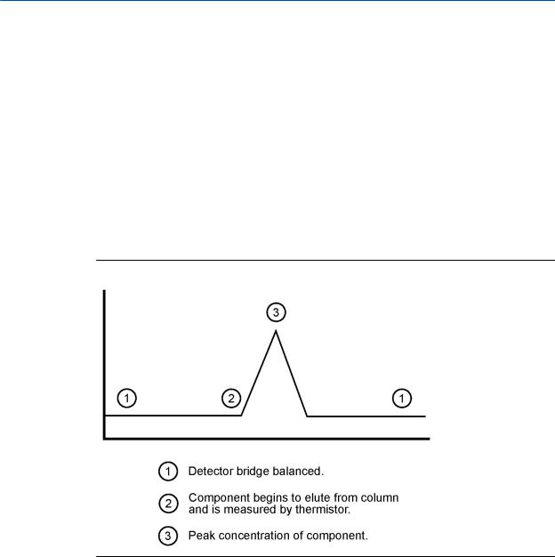
The differential signal developed between the two thermistors is amplified by the preamplifier. Figure 1-3 illustrates the change in detector electrical output during elution of a component.
Figure 1-3: Detector output during component elution
In addition to amplifying the differential signal developed between the two thermistors, the preamplifier supplies drive current to the detector bridge.
The signal is proportional to the concentration of a component detected in the gas sample. The preamplifier provides four different gain channels as well as compensation for baseline drift.
The signals from the preamplifier are sent to the electronic assembly for computation, recording on a printer, or viewing on a PC monitor with MON2020.
6
Introduction
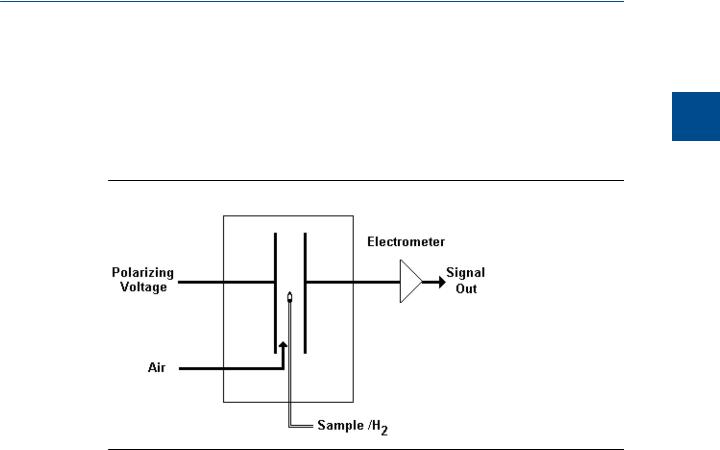
1.5.2Flame ionization detector
The other detector available for the 700XA is the flame ionization detector (FID). The FID requires a polarization voltage and its output is connected to the input to a high impedance amplifier that is called an electrometer. The burner uses a mixture of hydrogen and air to maintain the flame. The sample of gas to be measured is also injected into the burner. See Figure 1-4 for a schematic diagram of the FID.
Figure 1-4: Analyzer assembly with FID detector bridge
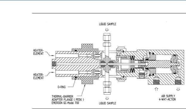
1.5.3Liquid sample injection valve
The optional liquid sample injection valve (LSIV) converts a liquid sample into a gas sample for GC analysis.
1 Introduction
7
Introduction
Figure 1-5: LSIV cross section
The LSIV penetrates the wall of the lower compartment and is held in place by a retaining ring. The mounting arrangement is designed to ensure integrity of the flameproof enclosure.
The outermost end houses an air-operated piston. Air at 60 PSI is directed by a solenoid valve to either advance the stem to inject the sample or to retract the stem.
The next section houses sample input connections and stem sealing components. There are two 1/8-inch O.D. tubing ports in this section; one port is for sample input, the other is the exhaust for sample flow.
Within the enclosure cavity are the flash chamber components surrounded with insulating covers. At working temperatures, the surfaces of these covers become very hot to the touch.
The tip of the cylindrical flash chamber is the port where flashed sample is taken to the oven system.
The port near the outer diameter of the end of the heated flash chamber block is the input for carrier gas.
The flash chamber block is stainless steel and is surrounded by an insulating mounting adapter. It houses the heater and an RTD.
1.5.4Methanator
After all other components have been separated from the sample, carbon monoxide and carbon dioxide, which are normally present in quantities too small to be detected by the GC, can be sent through the optional methanator, where the two gases are combined with hydrogen to make methane in a heat-generated catalytic reaction. The methanator is also known as a methanizer or a catalytic converter.
8

Introduction
1.5.5Data acquisition
Every second, exactly 50 equally spaced data samples are taken (i.e., one data sample every 20 milliseconds) for analysis by the controller assembly.
As a part of the data acquisition process, groups of incoming data samples are averaged together before the result is stored for processing. Non-overlapping groups of N samples are averaged and stored, and thus reduce the effective incoming data rate to 40/N samples per second. For example, if N = 5, then a total of 40/5 or 8 (averaged) data samples are stored every second.
The value for the variable N is determined by the selection of a Peak Width parameter (PW). The relationship is
N = PW
where PW is given in seconds. Allowable values of N are 1 to 63; this range corresponds to PW values of 2 to 63 seconds.
The variable N is known as the integration factor. This term is used because N determines how many points are averaged, or integrated, to form a single value. The integration of data upon input, before storing, serves two purposes:
•The statistical noise on the input signal is reduced by the square root of N. In the case of N = 4, a noise reduction of two would be realized.
•The integration factor controls the bandwidth of the chromatograph signal. It is necessary to match the bandwidth of the input signal to that of the analysis algorithms in the controller assembly. This prevents small, short-duration perturbations from being recognized as true peaks by the program. It is therefore important to choose a Peak Width that corresponds to the narrowest peak in the group under consideration.
1.5.6Peak detection
For normal area or peak height concentration evaluation, the determination of a peak's start point and end point is automatic. The manual determination of start and end points is used only for area calculations in the Forced Integration mode. Automatic determination of peak onset or start is initiated whenever Integrate Inhibit is turned off. Analysis is started in a region of signal quiescence and stability, such that the signal level and activity can be considered as baseline values.
Note
The controller assembly software assumes that a region of signal quiescence and stability will exist.
Having initiated a peak search by turning Integrate Inhibit off, the controller assembly performs a point by point examination of the signal slope. This is achieved by using a digital slope detection filter, a combination low pass filter and differentiator. The output is continually compared to a user-defined system constant called Slope Sensitivity. A default value of 8 is assumed if no entry is made. Lower values make peak onset detection more sensitive, and higher values make detection less sensitive. Higher values (20 to 100) would be appropriate for noisy signals, e.g. high amplifier gain.
1 Introduction
9

Introduction
Onset is defined where the detector output exceeds the baseline constant, but peak termination is defined where the detector output is less than the same constant.
Sequences of fused peaks are also automatically handled. This is done by testing each termination point to see if the region immediately following it satisfies the criteria of a baseline. A baseline region must have a slope detector value less than the magnitude of the baseline constant for a number of sequential points. When a baseline region is found, this terminates a sequence of peaks.
A zero reference line for peak height and area determination is established by extending a line from the point of the onset of the peak sequence to the point of the termination. The values of these two points are found by averaging the four integrated points just prior to the onset point and just after the termination points, respectively.
The zero reference line will, in general, be non-horizontal, and thus compensates for any linear drift in the system from the time the peak sequence starts until it ends.
In a single peak situation, peak area is the area of the component peak between the curve and the zero reference line. The peak height is the distance from the zero reference line to the maximum point on the component curve. The value and location of the maximum point is determined from quadratic interpolation through the three highest points at the peak of the discrete valued curve stored in the controller assembly.
For fused peak sequences, this interpolation technique is used both for peaks, as well as, valleys (minimum points). In the latter case, lines are dropped from the interpolated valley points to the zero reference line to partition the fused peak areas into individual peaks.
The use of quadratic interpolation improves both area and height calculation accuracy and eliminates the effects of variations in the integration factor on these calculations.
For calibration, the controller assembly may average several analyses of the calibration stream.
1.6Basic analysis computations
Two basic analysis algorithms are included in the controller assembly:
•Area Analysis – calculates area under component peak
•Peak Height Analysis – measures height of component peak
Note
For additional information about other calculations performed, see the MON2020 user manual.
1.6.1Concentration analysis - response factor
Concentration calculations require a unique response factor for each component in an analysis. These response factors may be manually entered by an operator or determined automatically by the system through calibration procedures (with a calibration gas mixture that has known concentrations).
10

Introduction
The response factor calculation, using the external standard, is:
ARFn |
= |
Arean |
or |
HRFn = |
H tn |
|
|||
Cal |
n |
|
Cal |
n |
|||||
|
|
|
|
|
|
|
|||
where |
|
|
|
|
|
|
|
|
|
|
|
|
|
|
|||||
ARFn |
|
|
|
area response factor for component “n” in area per mole percent |
|||||
Arean |
|
|
|
area associated with component “n” in calibration gas |
|||||
Caln |
|
|
|
amount of component “n” in mole percent in calibration gas |
|||||
Htn |
|
|
|
peak height associated with component “n” mole percent in calibration gas |
|||||
HRFn |
|
|
|
peak height response factor for component “n” |
|||||
Calculated response factors are stored by the controller assembly for use in the concentration calculations, and are printed out in the configuration and calibration reports.
Average response factor is calculated as follows:
|
k |
||
|
R Fi |
||
RFAV G = |
i=1 |
|
|
|
k |
||
n |
|
||
where |
|
|
|
|
|
|
|
RFAVGn |
|
area or height average response factor for component “n” |
|
RFi |
|
area or height average response factor for component “n” from the calibration run |
|
k |
|
number of calibration runs used to calculate the response factors |
|
|
|
|
|
The percent deviation of new RF averages from old RF average is calculated in the following manner:
deviation = |
|
|
R Fnew |
R Fold |
× 100 |
|
|||||
|
|
R Fold |
|||
|
|
|
|
||
|
|
|
|||
where the absolute value of percent deviation has been previously entered by the operator.
1.6.2Concentration calculation - mole percentage (without normalization)
Once response factors have been determined by the controller assembly or entered by the operator, component concentrations are determined for each analysis by using the following equations:
1 Introduction
11

Introduction
CON Cn = |
Arean |
or CON Cn = |
H tn |
|
|||
AR F |
n |
HR F |
n |
||||
|
|
|
|
|
|||
where |
|
|
|
|
|
|
|
|
|
|
|||||
ARFn |
|
Area response factor for component “n” in area per mole percent. |
|||||
Arean |
|
Area associated with component “n” in unknown sample. |
|||||
CONCn |
|
Concentration of component “n” in mole percent. |
|||||
Htn |
|
Peak height associated with component “n” mole percent in unknown sample. |
|||||
HRFn |
|
Peak height response factor for component “n”. |
|||||
Component concentrations may be input through analog inputs 1 to 4 or may be fixed. If a fixed value is used, the calibration for that component is the mole percent that will be used for all analyses.
1.6.3Concentration calculation in mole percentage (with normalization)
The normalized concentration calculation is:
CONC Nn = |
|
CON Cn |
× 100 |
|
k |
CON Ci |
|||
|
|
|||
|
i=1 |
|
||
where |
|
|
||
|
|
|
||
CONCNn |
|
Normalized concentration of component “n” in percent of total gas concentration. |
||
CONCi |
|
Non-normalized concentration of component “n” in mole percent for each “k” |
||
|
|
|
component. |
|
|
|
|
||
CONCn |
|
Non-normalized concentration of component “n” in mole percent. |
||
k |
|
Number of components to be included in the normalization. |
||
|
|
|
|
|
Note
The average concentration of each component will also be calculated when data averaging is requested.
1.7Glossary
Auto Zero |
Automatic zeroing of the TCD preamplifier can be configured to take |
|
place at any time during the analysis if the component is not eluting or |
|
the baseline is steady.The FID will auto zero at each new analysis run |
12
Introduction
|
and can be configured to auto zero anytime during the analysis if the |
||
|
component is not eluting or the baseline is steady. The TCD is only |
||
|
auto zeroed at the start of a new analysis. |
||
Baseline |
Signal output when there is only carrier gas going across the |
||
|
detectors. In a chromatogram you should only see Baseline when |
||
|
running an analysis without injecting a sample. |
||
Carrier gas |
The gas used to push the sample through the system during an |
||
|
analysis. In C6+ analysis we use Ultra Pure (zero grade) Carrier Gas for |
||
|
the carrier. This gas is 99.995 percent pure. |
||
Chromatogram |
A permanent record of the detector output. A chromatogram is |
||
|
obtained from a PC interfaced with the detector output through the |
||
|
controller assembly. A typical chromatogram displays all component |
||
|
peaks, and gain changes. It may be viewed in color as it is processed |
||
|
on a PC VGA display. Tick marks recorded on the chromatogram by |
||
|
the controller assembly indicate where timed events take place. |
||
Component |
Any one of several different gases that may appear in a sample |
||
|
mixture. For example, natural gas usually contains the following |
||
|
components: nitrogen, carbon dioxide, methane, ethane, propane, |
||
|
isobutane, normal butane, isopentane, normal pentane, and hexanes |
||
|
plus. |
||
CTS |
Clear to send. |
||
DCD |
Data carrier detect. |
||
DSR |
Data set ready. |
||
DTR |
Data terminal ready. |
||
FID |
Flame ionization detector. The optional FID may be used in place of a |
||
|
TCD for the detection of trace compounds. The FID requires a |
||
|
polarization voltage and its output is connected to the input to a high |
||
|
impedance amplifier, an electrometer. The sample of gas to be |
||
|
measured is injected into the burner with a mixture of hydrogen and |
||
|
air to maintain the flame. |
||
LSIV |
Liquid sample injection valve. The optional LSIV is used to convert a |
||
|
liquid sample to a gas sample by vaporizing the liquid in a heated |
||
|
chamber, then analyzing the flashed sample. |
||
Methanator |
The optional methanator, also known as a catalytic converter, |
||
|
transforms otherwise undetectable carbon dioxide and/or carbon |
||
|
monoxide into methane by adding hydrogen and heat to the sample. |
||
Response factor |
Correction factor for each component as determined by the following |
||
|
calibration: |
||
|
RF = |
RawArea |
|
|
Calibration Concentration |
|
|
Retention time |
Time, in seconds, that elapses between the start of analysis and the |
||
|
sensing of the maximum concentration of each component by the |
||
|
detector. |
||
RI |
Ring indicator. |
||
RLSD |
Received line signal detect. A digital simulation of a carrier detect. |
||
RTS |
Request to send. |
||
1 Introduction
13

Introduction
RxD, RD, or Sin |
Receive data, or signal in. |
TCD |
Thermal conductivity detector. A detector that uses the thermal |
|
conductivity of the different gas components to produce an |
|
unbalanced signal across the bridge of the preamplifier. The higher |
|
the temperature, the lower the resistance on the detectors. |
TxD, TD, or Sout |
Transmit data, or signal out. |
14
Equipment description and specifications
2 Equipment description and specifications
Use the following sections to reference the 700XA equipment description or specifications.
2.1Equipment description
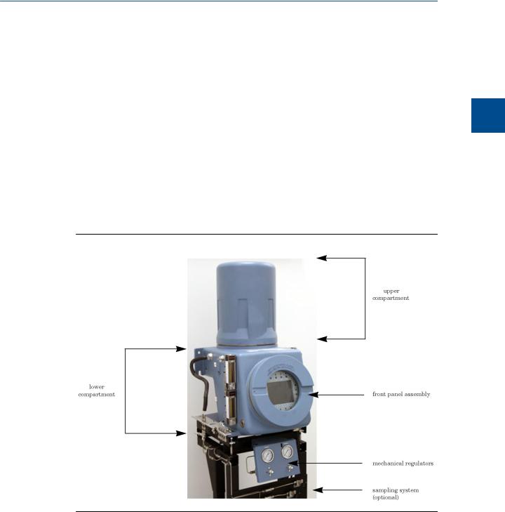
The 700XA consists of a copper-free aluminum explosion-proof chamber, and a front panel assembly. The chamber is divided into two compartments that together house the GC’s major components. This unit is designed for hazardous locations.
Figure 2-1: 700XA gas chromatograph
2.1.1Front panel assembly
The front panel assembly is located on the front section of the lower enclosure and consists of a removable, explosion-proof panel that shields either a switch panel or a local operator interface (LOI).
2 Equipment description and specificat
15
Equipment description and specifications
The switch panel
The switch panel contains a network of on/off switches that allow you to manually control the GC’s stream and analytical valves.
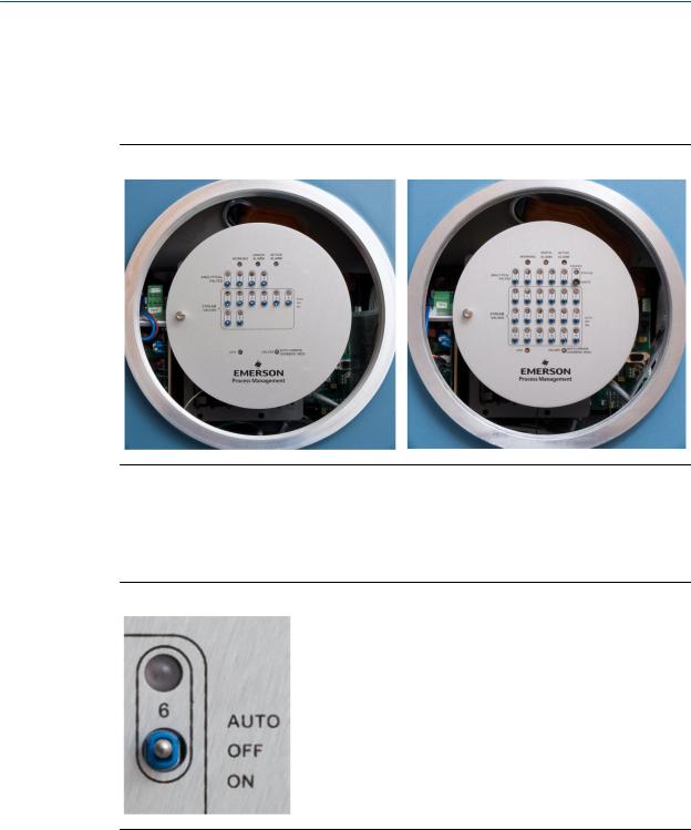
Figure 2-2: 8-stream switch panel (left) and 18-stream switch panel (right)
There are two types of switch panels: 8-stream and 18-stream. The 8- stream switch panel is the standard panel, and is used when the GC has only one heater/solenoid board installed; if two heater/solenoid boards are installed, then the 18-stream switch panel is used.
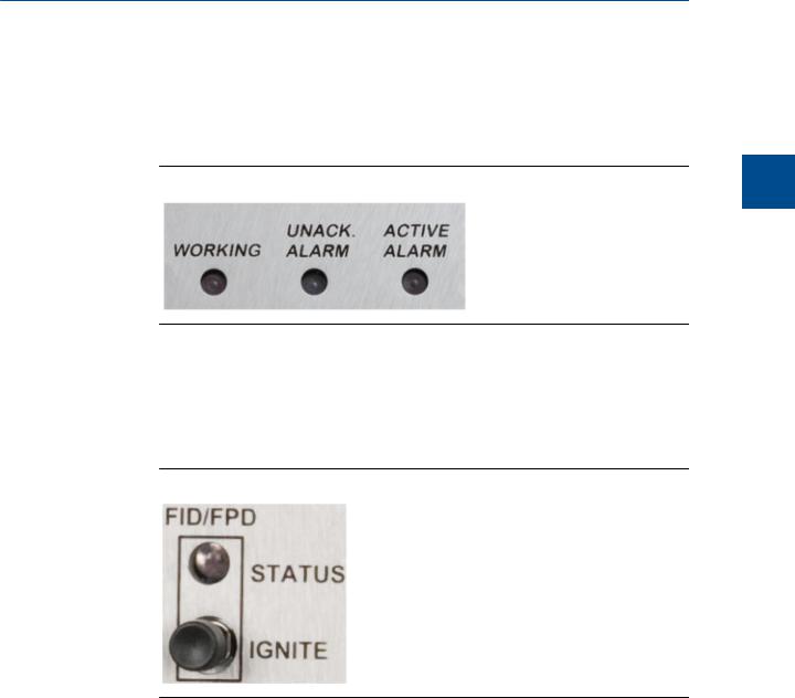
Figure 2-3: Valve switch from switch panel set to “OFF”
A valve has the following three operational modes:
•AUTO - The valve turns on and off according to the Timed Events table that is accessible through MON2020. To set a valve to AUTO mode, set its switch on the switch panel to the “up” position.
16
Equipment description and specifications
•OFF - The valve turns off and remains off until the operational mode is changed. To set a valve to OFF mode, set its switch on the switch panel to the “center” position—that is, the switch is neither flipped “up” nor “down”.
•ON - The valve turns on and remains on until the operational mode is changed. To set a valve to ON mode, set its switch on the switch panel to the “down” position.
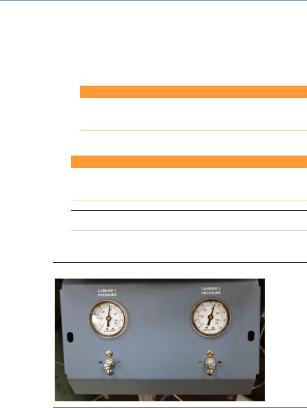
Figure 2-4: Status LEDs (Top of switch panel)
The switch panels also contain the following status lights that allow you to monitor the GC’s condition:
• Working - Turns green when the GC is in analysis mode.
• Unack. Alarm - Turns yellow if there is an unacknowledged alarm.
• Active Alarm - Turns red if there is an active alarm.
Figure 2-5: FID/FPD Status LED
•FID/FPD - The 18-stream switch panel contains a FID or FPD status LED that can indicate the following:
-A green light means the flame has ignited.
-A flashing yellow light means an attempt is being made to ignite the flame.
-A red light means the flame as gone out or that the FID or FPD is overtemperature.
2 Equipment description and specificat
17

Equipment description and specifications
Figure 2-6: Status LEDs (Bottom of switch panel)
•CPU - Green light blinks continuously while the GC is running.
•Valves - Turns green if the valves are functioning automatically; turns red if the valves’ automatic settings have been overridden.
Note
During GC start up, all LEDs turn on for approximately ten seconds.
The local operator interface
The optional local operator interface (LOI) gives you more in-depth control over the GC’s functions than does the switch panel. It has a high resolution color display that is touch key activated and allows you to operate a 700XA GC without a laptop or a PC.
Figure 2-7: The local operator interface
The LOI includes the following features:
•Color LCD with VGA (640 x 480 pixels) resolution.
•ASCII text and graphics modes.
•Adjustable auto-backlighting.
18

Equipment description and specifications
•8 infrared-activated touch screen keys that eliminate the requirement for a magnetic pen.
•Complete GC status, control and diagnostics, including full chromatogram display.
See Appendix A for more information about operating the LOI.
2.1.2Upper compartment
The upper compartment contains the following components:
•Valves. There are two types of XA valves: 6-port and 10-port. A 700XA can have a maximum of four XA valves consisting of any combination of the two types.
•Column module. Either capillary or micro-packed.
•Thermal conductivity detector (TCD). The 700XA has a minimum of one TCD and a maximum of two TCDs.
•Two heating elements: a “top hat” heater and a column heater.
•One temperature switch for each heating element. The switch turns off its heating element if the heating element reaches 257° F (160° C).
•Pressure switch. The pressure switch activates when the carrier pressure falls below a predetermined set point. When activated, the switch triggers a general alarm that displays on the front panel or LOI and in MON2020.
•Flame ionization detector (FID). The optional FID, which detects trace levels of hydrocarbons, can be used in place of one TCD.
•Flame photometric detector (FPD). The optional FPD, which detects trace levels of sulphur compounds, can be used in place of a TCD. Installed as a "side car" component. For more information, refer to the FPD for Gas Chromatographs Hardware Reference Manual.
•Methanator. The methanator, or catalytic converter, is an optional component that converts otherwise undetectable carbon dioxide and/or carbon monoxide into methane by adding hydrogen and heat to the sample.
•Liquid sample injection valve (LSIV). The optional LSIV is used to vaporize a liquid sample, thereby expanding the GC’s capability to measure liquids.
2.1.3Lower compartment
The lower compartment consists of the following components:
•Backplane. The backplane is the GC’s central printed circuit board (PCB). Its main function is as a connection point for the GC’s specialized plug-in PCBs. The backplane also hosts connections for analog outputs and analog inputs, serial ports and an Ethernet port.
•Card cage. The card cage holds the specialized PCBs that plug into the backplane. The following PCBs are housed in the card cage:
-Preamp board
-CPU board
-Base I/O board
2 Equipment description and specificat
19
Equipment description and specifications
-Heater/Solenoid board
The card cage also has four additional slots for the following optional PCBs:
-A second preamp board
-A second heater/solenoid board
-Two optional communications boards
 WARNING!
The explosion-proof housing should not be opened when the unit is exposed to an explosive environment. If access to the explosion-proof housing is required, take precautions to ensure that an explosive environment is not present. Failure to do so may result in injury or death to personnel or cause damage to the equipment.
•Optional AC/DC power supply.
 WARNING!
See power supply label prior to connection. Check the unit power design to determine if it is equipped for AC or DC power. Applying 110/220 VAC to a DC power input unit will severely damage the unit. Failure to do so may result in injury or death to personnel or cause damage to the equipment.
Note
The 700XA CSA-certified unit is equipped with 3/4-inch NPT-thread adapters.
2.1.4Mechanical pressure regulators
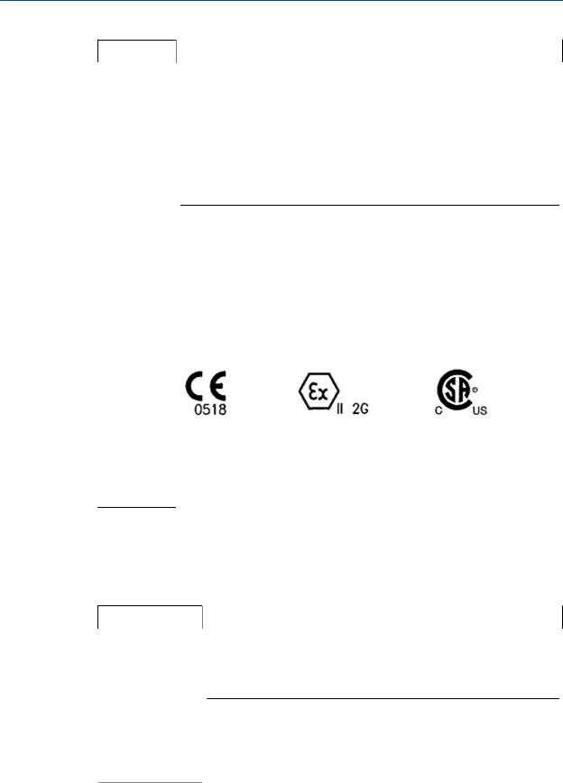
Figure 2-8: The mechanical pressure regulators
20

Equipment description and specifications
The mechanical pressure regulators and gauges are used to set and monitor the pressure of the carrier gas flow through the GC's columns, as well as the pressure of the FID air and fuel (H2).
The regulators and gauges are located beneath the GC.
2.2Equipment specifications
2.2.1Utilities
Use the following table to determine the utility specifications.
Type |
Specification |
|
|
|
|
Unit dimen- |
• |
Basic unit envelope |
sions |
|
W - 15.2” (387 mm) |
|
|
|
|
|
H - 41.5” (1054 mm) |
|
|
D - 19.2” (488 mm) |
|
• |
Wall mount |
|
|
W - 18.2” (463 mm) |
|
|
H - 41.5” (1054 mm) |
|
|
D - 19.2” (488 mm) |
|
• |
Pole mount |
|
|
W - 18.2” (463 mm) |
|
|
H - 41.5” (1054 mm) |
|
|
D - 25.0” (635 mm) |
|
• |
Floor mount |
|
|
W - 18.2” (463 mm) |
|
|
H - 58.0” (1470 mm) |
|
|
D - 19.2” (488 mm) |
|
Note |
|
|
Allow 14” (360 mm additional) clearance for removal of dome. |
|
|
|
|
|
|
|
Unit weight |
• Wall mount - 110 lbs (59 kg) |
|
|
• Pole mount - 135 lbs (61 kg) |
|
|
• Floor mount - 180 lbs (82 kg) |
|
|
|
|
Tubing |
• 316 stainless steel |
|
|
• 316 stainless steel and Kapton® in contact with sample |
|
|
• Sulfinert® steel (optional) |
|
2 Equipment description and specificat
21
Equipment description and specifications
Type |
Specification |
||
|
|
|
|
Mounting |
• |
Floor mount |
|
|
• |
Pole mount: |
|
|
|
- |
2” (60.3 mm) |
|
|
- |
3” (89.0 mm) |
|
|
- |
4” (114.3 mm) |
|
• |
Direct wall mount |
|
|
|
|
|
Power |
• |
24V DC standard (21-30 V DC operating voltage range); MAX 150 watts |
|
|
• (optional) 100-120/240 V AC; 50-60 Hz |
||
|
Note |
|
|
Voltage range includes line voltage variations. |
|
|
|
|
|
|
|
Instrument air |
Not required; optional for valve actuation, minimum pressure of 90 psig |
|
|
|
|
Environment |
• Hazardous area certified: -20o C to 60o C (-4o F to 140o F) |
|
|
• 0 to 95% RH (non-condensing) |
|
|
• Indoor/outdoor |
|
|
• Pollution - degree 2 (The unit can withstand some non conductive environ- |
|
|
mental pollutants e.g., humidity.) |
|
|
|
|
Approvals |
|
|
FOR USE IN HAZARDOUS LOCATIONS:
•For Canada: Class I, Zone 1, EX d IIC T6, Enclosure Type 4 Class I, Division 1, Group B, C and D.
•For USA: Class I, Zone 1, EX d IIC T6, Enclosure Type 4 Class I, Division 1, Group B, C and D.
2.2.2Electronic hardware
Use the following table to determine the electronic hardware specifications:
Type |
Specification |
|
|
Rating |
Division 1; no purge required |
|
|
Communication |
3 configurable Modbus ports that support RS-232/422/485 protocols; 2 op- |
ports |
tional ports in expansion slots; 9-pin RS-232 port. |
|
Note |
|
|
The maximum number of simultaneous Modbus TCP/IP connections from |
|
|
Modbus Master is 10. |
|
|
|
|
|
|
|
Optional modem |
56K Baud Telephone |
|
22
Loading...