


Instruction Manual
Form 5464
July 2010
Type 289RC
Type 289RC Exhaust Booster
W7313
W7322
Figure 1. Type 289RC Exhaust Booster
Introduction
Scope of the Manual
This manual describes the principles of operation and provides installation instructions and a parts list for the Type 289RC exhaust booster.
Product Description
The Type 289RC high-capacity exhaust booster provides “release control (RC)” control pressure to actuators, other pneumatic devices, and related
systems that require rapid response, such as surge valves or recycle valves on compressors. This exhaust booster is normally used on control valve actuators to speed up the proportional operation of a
control valve in response to sudden pressure changes from pneumatic output devices, such as solenoid valves or pneumatic instruments. By carefully matching the instrument and actuator performance with the bypass valve adjustment, the Type 289RC reduces overshoot and related problems while allowing very fast positioning response to system requirements (i.e., compressor surge control). The one-way throttling action offers superior control with exceptional stability and the specially designed boosting system provides high flow rates with minimum buildup.
Specifications
Specifications for the Type 289RC exhaust booster are listed on page 2. Specifications for a given exhaust booster as it originally comes from the factory are stamped on the nameplate.
D102588X012
www.fisherregulators.com

Type 289RC
Specifications
Body Size(1)
1 NPT
Inlet and Outlet Connections
Inlet: Connect to the outlet via a bypass valve, adjustable from 0 to 0.3 Cv. (Piping is normally configured by the customer.) See Figure 3.
Signal: 1/8 NPT (standard) Outlet: 1 NPT
Maximum Pressure(1)
125 psig (8,6 bar)
Input to Output Pressure Ratio
Fixed at 1 to 1
Dead Band
0.5 psid (0,034 bar d) pressure across the bypass valve
Maximum Exhaust Flow Capacity
Cv = 22. System capacity limited by the smallest restriction between the exhaust valve and pressure source (actuator).
Temperature Capabilities(1)
-20° to 180°F (-29° to 82°C)
Approximate Weight
4 pounds (2 kg)
1. The pressure/temperature limits in this Instruction Manual and any applicable standard or code limitation should not be exceeded.
Principle of Operation
The Type 289RC 1 NPT outlet port is connected directly to a spring return actuator and the 1/8 NPT inlet connection on the spring case is connected to the controlling instrument (I/P transducer, controller, positioner, etc.). The assembly of the Type 289RC to a control valve requires the inlet and outlet chambers be connected via a bypass valve. The bypass valve should be installed between the two
1/8 NPT connections on the Type 289RC or any other convenient location per the customer’s preference. The Type 289RC exhaust booster has a factory set opening threshold of 0.5 psid (0,03 bar d). The adjustment screw in the booster body is not field adjustable. The bypass valve is adjusted on the control valve system
to account for differences in various instrument and actuator performance characteristics. Once adjusted, the control valve action is as described in the following paragraph.
As the output pressure of the instrument increases the actuator moves the valve normally since the exhaust booster cannot be actuated with an increasing signal. When the output pressure of the instrument decreases the actuator will move the valve until the rate of change of the output pressure develops 0.5 psid (0,034 bar d) across the bypass valve. When this occurs, the pressure differential in the Type 289RC causes the exhaust booster valve to begin opening and begin reducing the pressure in the actuator. The greater the differential pressure develops across the bypass valve, the further the exhaust booster will
open. The booster exhaust valve closes as the pressure difference between the instrument and actuator decreases.
Installation
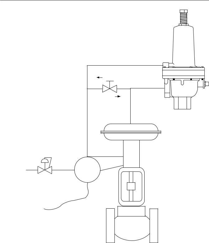
The schematic on page 3 (Figure 2) shows the typical Type 289RC installation. Connect the instrument supply to the 1/8 NPT spring case inlet and the actuator to the 1 NPT side port outlet. The inlet and outlet must be connected via an adjustable bypass valve. Flow through the exhaust valve must be in the same direction as the flow arrow on the body.
Note
Mounting is recommended with the outlet exhaust connection pointing down. If it is necessary to pipe this outlet away from the area, remove the outlet screen.
caution
Protect the outlet exhaust connection against the entrance of rain, snow, insects, or any other foreign material that may block the outlet or affect the opening and closing of the valve.
2
Type 289RC
|
METERED FLOW |
|
FREE FLOW |
|
Adjustable |
|
bypass valve |
|
(0 to 0.3 Cv) |
Instrument Supply |
I/P |
45 to 125 psig |
|
(3,1 to 8,6 bar) |
|
4 to 20 mA
A7208
Type 289RC
Figure 2. Typical Type 289RC Exhaust Booster and Control Valve Installation
3
 Loading...