


TM UNVENTED (VENT-FREE) GAS FIREPLACE
OWNER’S OPERATION AND INSTALLATION MANUAL


 For
For


 visit
visit
 .
.

 .com
.com


Shown with optional cabinet mantel, |
Shown with optional hearth |
hearth base, and trim accessories. |
base accessory. |
CGEFP33PR, CGEFP33NR, EFP33PR, EFP33NR,
VTGF33NR, and VTGF33PR
Gas Fireplace with Total Control System (TCS)
WARNING: If the information in this manual is not followed exactly, a fire or explosion may result causing property damage, personal injury, or loss of life.
—Do not store or use gasoline or other flammable vapors and liquids in the vicinity of this or any other appliance.
—WHAT TO DO IF YOU SMELL GAS
•Do not try to light any appliance.
•Do not touch any electrical switch; do not use any phone in your building.
•Immediately call your gas supplier from a neighbor’s phone. Follow the gas supplier’s instructions.
•If you cannot reach your gas supplier, call the fire department.
—Installation and service must be performed by a qualified installer, service agency, or the gas supplier.
WARNING: Improper installation, adjustment, alteration, service, or maintenance can cause injury or property damage. Refer to this manual for correct installation and operational procedures. For assistance or additional information consult a qualified installer, service agency, or the gas supplier.
WARNING: This is an unvented gasfired heater. It uses air (oxygen) from the room in which it is installed. Provisions for adequate combustion and ventilation air must be provided. Refer to Air for Combustion and Ventilation section on page 5 of this manual.
This appliance may be installed in an aftermarket,* permanently located, manufactured (mobile) home, where not prohibited by local codes.
This appliance is only for use with the type of gas indicated on the rating plate. This appliance is not convertible for use with other gases.
* Aftermarket: Completion of sale, not for purpose of resale, from the manufacturer

 Save this
 for future

 .
.


TABLE OF CONTENTS 2 SAFETY INFORMATION
TABLE OF CONTENTS |
|
SAFETY INFORMATION ............................................................ |
2 |
PRODUCT IDENTIFICATION ..................................................... |
3 |
LOCAL CODES ........................................................................... |
4 |
UNPACKING ............................................................................... |
4 |
PRODUCT FEATURES .............................................................. |
4 |
AIR FOR COMBUSTION AND VENTILATION ........................... |
5 |
INSTALLATION ........................................................................... |
7 |
OPERATING FIREPLACE ........................................................ |
24 |
INSPECTING BURNERS .......................................................... |
27 |
CLEANING AND MAINTENANCE ............................................ |
28 |
TROUBLESHOOTING .............................................................. |
29 |
SPECIFICATIONS .................................................................... |
|
32 |
SERVICE HINTS ....................................................................... |
|
32 |
TECHNICAL SERVICE ............................................................. |
|
32 |
REPLACEMENT PARTS .......................................................... |
|
32 |
WIRING DIAGRAM ................................................................... |
|
33 |
ILLUSTRATED PARTS BREAKDOWN AND PARTS LIST ....... |
34 |
|
ACCESSORIES ........................................................................ |
|
42 |
TEMPLATES ............................................................................. |
|
45 |
OWNER’S REGISTRATION FORM .......................................... |
|
47 |
WARRANTY INFORMATION ...................................... |
Back Cover |
|
SAFETY INFORMATION
 WARNINGS
IMPORTANT: Read this owner’s manual carefully and completelybeforetryingtoassemble,operate,orservice this fireplace. Improper use of this fireplace can cause serious injury or death from burns, fire, explosion, electrical shock, and carbon monoxide poisoning.
 DANGER: Carbon monoxide poisoning may lead to death!
Carbon Monoxide Poisoning: Early signs of carbon monoxide poisoning resemble the flu, with headaches, dizziness, or nausea. If you have these signs, the fireplace may not be working properly. Get fresh air at once! Have fireplace serviced. Some people are more affected by carbon monoxide than others. These include pregnant women, people with heart or lung disease or anemia, those under the influence of alcohol, and those at high altitudes.
Natural and Propane/LP Gas: Natural and Propane/LP gases are odorless. An odor-making agent is added to these gases. The odor helps you detect a gas leak. However, the odor added to the gas can fade. Gas may be present even though no odor exists.
Make certain you read and understand all warnings. Keep this manual for reference. It is your guide to safe and proper operation of this fireplace.
 WARNING: Any change to this heater or its controls can be dangerous.
 WARNING: Do not allow fans to blow directly into the fireplace. Avoid any drafts that alter burner flame patterns. Ceiling fans can create drafts that alter burner flame patterns. Altered burner patterns can cause sooting.
 WARNING: Do not use a blower insert, heat exchanger insert, or other accessory not approved for use with this fireplace.
Due to high temperatures, the appliance should be located out of traffic and away from furniture and draperies.
Do not place clothing or other flammable material on or near the appliance. Never place any objects on the heater.
Fireplace front and screen become very hot when running fireplace. Keep children and adults away from hot surfaces to avoid burns or clothing ignition. Fireplace will remain hot for a time after shutdown. Allow surfaces to cool before touching.
Carefully supervise young children when they are in the room with fireplace. When using the hand-held remote accessory, keep selector switch in the OFF position to prevent children from turning on burners with remote.
You must operate this fireplace with the fireplace screen and hood in place. Make sure fireplace screen and hood are in place before running fireplace.
Keep the appliance area clear and free from combustible materials, gasoline, and other flammable vapors and liquids.


 For
For


 visit
visit
 .
.

 .com
.com


108117-01G
SAFETY INFORMATION |
3 |
PRODUCT IDENTIFICATION |
SAFETY INFORMATION
Continued
1.This appliance is only for use with the type of gas indicated on the rating plate. This appliance is not convertible for use with other gases.
2.Do not place propane/LP supply tank(s) inside any structure. Locate propane/LP supply tank(s) outdoors.
3.If you smell gas
•shut off gas supply
•do not try to light any appliance
•do not touch any electrical switch; do not use any phone in your building
•immediately call your gas supplier from a neighbor’s phone. Follow the gas supplier’s instructions
•if you cannot reach your gas supplier, call the fire department
4.This fireplace shall not be installed in a bedroom or bathroom.
5.Do not use this fireplace as a wood-burning fireplace. Use only the logs provided with the fireplace.
6.Do not add extra logs or ornaments such as pine cones, vermiculite, or rock wool. Using these added items can cause sooting. Do not add lava rock around base. Rock and debris could fall into the control area of fireplace.
7.To prevent the creation of soot, follow the instructions in Cleaning and Maintenance, page 28.
8.Before using furniture polish, wax, carpet cleaner, or similar products, turn heater off. If heated, the vapors from these products may create a white powder residue within burner box or on adjacent walls or furniture.
9.This fireplace needs fresh air ventilation to run properly. This fireplace has an Oxygen Depletion Sensing (ODS) safety shutoff system. The ODS shuts down the fireplace if not enough fresh air is available. See Air for Combustion and Ventilation, pages 5 through 7. If fireplace keeps shutting off, see Troubleshooting, pages 29 through 31.
10.Do not run fireplace
•where flammable liquids or vapors are used or stored
•under dusty conditions
11.Do not use this fireplace to cook food or burn paper or other objects.
12.Do not use fireplace if any part has been exposed to or under water. Immediately call a qualified service technician to inspect the fireplace and to replace any part of the control system and any gas control which has been under water.
13.Do not operate fireplace if any log is broken. Do not operate fireplace if a log is chipped (dime-sized or larger).
14.Turn fireplace off and let cool before servicing. Only a qualified service person should service and repair fireplace.
15.Operating fireplace above elevations of 4,500 feet could cause pilot outage.
16.To prevent performance problems with propane/LP units, do not use propane/LP fuel tanks of less than 100 lb. capacity.
17.Provide adequate clearances around air openings.
PRODUCT IDENTIFICATION
Manual |
|
Log Set |
|
Override |
|
|
|
Handle |
|
|
|
Remote |
Piezo |
|
|
Control |
|
||
Ignitor |
Manual Ignition |
||
|
|||
|
|
||
|
Wall Switch/Plate |
Bypass Switch |
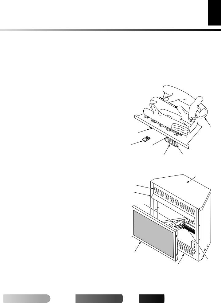
Figure 1 - Fireplace Floor Assembly (EFP33PR Shown)
Top Outer
Casing
Top Louver
Assembly
Firebox
Hood
Firebox Support
Screen
Assembly
|
Blower |
|
Bottom Louver |
Assembly |
|
(Optional) |
||
Assembly |
||
|
Figure 2 - Fireplace (EFP33PR Shown)
 For more

 visit www.

 .com
.com


108117-01G

LOCAL CODES 4 UNPACKING
PRODUCT FEATURES
LOCAL CODES
Install and use fireplace with care. Follow all local codes. In the absence of local codes, use the latest edition of The National Fuel Gas Code, ANSI Z223.1/NFPA 54*.
*Available from:
American National Standards Institute, Inc.
1430 Broadway
New York, NY 10018
National Fire Protection Association, Inc.
Batterymarch Park
Quincy, MA 02269
UNPACKING
 CAUTION: Do not remove the data plates attached to the heater base assembly. The data plates contain important warranty and safety information.
1.With utility knife, cut the carton all the way around above the staples on the bottom tray. Lift the carton off the heater. Remove packing. Note: The hood is located in the packing on the right hand side of the heater front. Lift the heater off the bottom tray.
2.Locate two screws above top corners of the fireplace screen. Remove and discard these screws. Lift fireplace screen up and pull out to remove.
3.Remove protective packaging applied to logs, log base assembly, and fireplace.
4.Remove fireplace hood from carton insert.
5.Check all items for any shipping damage. If damaged, promptly inform dealer where you bought fireplace.
PRODUCT FEATURES
OPERATION
This vent-free fireplace is clean burning. It requires no outside venting. There is no heat loss out a vent or up a chimney. Heat is generated by both realistic flames and glowing embers. When used without the optional blower, the fireplace requires no electricity making it ideal for emergency backup heat.
SAFETY DEVICE
This fireplace has a pilot with an Oxygen Depletion Sensing (ODS) safety shutoff system. The ODS/pilot is a required feature for ventfree room heaters. The ODS/pilot system shuts off the fireplace if there is not enough fresh air.
PIEZO IGNITION SYSTEM
This fireplace has a piezo ignitor. This system requires no matches, batteries, or other sources to light fireplace.
WIRELESS REMOTE CONTROL
This fireplace features an infrared wireless remote control. This control system can be used to automatically light the pilot and adjust the burner flame height at the push of a button.
WIRED WALL-MOUNTED REMOTE CONTROL
This fireplace features a two-button wall switch and wall plate with glowing LED’s. The wall switch performs the same functions as the wireless hand-held remote control with the added feature of LED’s for visual feedback of operation and status.
OPTIONAL BLOWER ASSEMBLY
ACCESSORY
This fireplace accepts an optional blower assembly (not included). The GA3650T/GA3700T Series blower operates thermostatically and features a variable speed control. The GA3700/GA3750 Series operates manually and also features a variable speed control. The blower circulates heated air from the fireplace into the room. Use of blower is optional. See Accessories, pages 42 and 43.


 For
For


 visit
visit
 .
.

 .com
.com


108117-01G

AIR FOR COMBUSTION AND VENTILATION |
5 |
Providing Adequate Ventilation |
AIR FOR COMBUSTION AND
VENTILATION
 WARNING: This heater shall not be installed in a confined space or unusually tight construction unless provisions are provided for adequate combustion and ventilation air. Read the following instructions to insure proper fresh air for this and other fuelburning appliances in your home.
Today’s homes are built more energy efficient than ever. New materials, increased insulation, and new construction methods help reduce heat loss in homes. Home owners weather strip and caulk around windows and doors to keep the cold air out and the warm air in. During heating months, home owners want their homes as airtight as possible.
While it is good to make your home energy efficient, your home needs to breathe. Fresh air must enter your home. All fuel-burning appliances need fresh air for proper combustion and ventilation.
Exhaust fans, fireplaces, clothes dryers, and fuel burning appliances draw air from the house to operate. You must provide adequate fresh air for these appliances. This will insure proper venting of vented fuel-burning appliances.
PROVIDING ADEQUATE VENTILATION
The following are excerpts from National Fuel Gas Code, ANSI Z223.1/NFPA 54, Section 5.3, Air for Combustion and Ventilation.
All spaces in homes fall into one of the three following ventilation classifications:
1.Unusually Tight Construction
2.Unconfined Space
3.Confined Space
The information on pages 5 through 7 will help you classify your space and provide adequate ventilation.
Unusually Tight Construction
The air that leaks around doors and windows may provide enough fresh air for combustion and ventilation. However, in buildings of unusually tight construction, you must provide additional fresh air.
Unusually tight construction is defined as construction where:
a.walls and ceilings exposed to the outside atmosphere have a continuous water vapor retarder with a rating of one perm (6 x 10-11 kg per pa-sec-m2) or less with openings gasketed or sealed and
b.weather stripping has been added on openable windows and doors and
c.caulking or sealants are applied to areas such as joints around window and door frames, between sole plates and floors, between wall-ceiling joints, between wall panels, at penetrations for plumbing, electrical, and gas lines, and at other openings.
If your home meets all of the three criteria above, you must provide additional fresh air. See Ventilation Air From Outdoors, page 7.
If your home does not meet all of the three criteria above, proceed to Determining Fresh-Air Flow for Fireplace Location on page 6.
Confined Space and Unconfined Space
The National Fuel Gas Code, ANSI Z223.1/NFPA 54 defines a confined space as a space whose volume is less than 50 cubic feet per 1,000 Btu per hour (4.8 m3 per kw) of the aggregate input rating of all appliances installed in that space and an unconfined space as a space whose volume is not less than 50 cubic feet per 1,000 Btu per hour (4.8 m3 per kw) of the aggregate input rating of all appliances installed in that space. Rooms communicating directly with the space in which the appliances are installed*, through openings not furnished with doors, are considered a part of the unconfined space.
* Adjoining rooms are communicating only if there are doorless passageways or ventilation grills between them.
 For more

 visit www.

 .com
.com


108117-01G
6 |
AIR FOR COMBUSTION AND VENTILATION |
Determining Fresh-Air Flow For Heater Location |
|
|
Ventilation Air |
|
|
AIR FOR COMBUSTION AND VENTILATION
Continued
DETERMINING FRESH-AIR FLOW FOR HEATER LOCATION
Determining if You Have a Confined or Unconfined Space
Use this work sheet to determine if you have a confined or unconfined space.
Space: Includes the room in which you will install heater plus any adjoining rooms with doorless passageways or ventilation grills between the rooms.
1.Determine the volume of the space (length x width x height). Length x Width x Height = ___________ cu. ft. (volume of space)
Example: Space size 20 ft. (length) x 18 ft. (width) x 8 ft. (ceiling height) = 3168 cu. ft. (volume of space)
If additional ventilation to adjoining room is supplied with grills or openings, add the volume of these rooms to the total volume of the space.
2.Multiply the space volume by 20 to determine the maximum Btu/Hr the space can support.
__________ (volume of space) x 20 = (Maximum Btu/Hr the space can support)
Example: 3168 cu. ft. (volume of space) x 20 = 63,360 (maximum Btu/Hr the space can support)
3.Add the Btu/Hr of all fuel burning appliances in the space.
Vent-free heater |
|
_____________ Btu/Hr |
Gas water heater* |
|
_____________ Btu/Hr |
Gas furnace |
|
_____________ Btu/Hr |
Vented gas heater |
|
_____________ Btu/Hr |
Gas fireplace logs |
|
_____________ Btu/Hr |
Other gas appliances* + |
_____________ Btu/Hr |
|
Total |
= |
_____________ Btu/Hr |
* Do not include direct-vent gas appliances. Direct-vent draws combustion air from the outdoors and vents to the outdoors.
Example: |
|
|
Gas water heater |
|
40,000 |
|
_____________ Btu/Hr |
|
Vent-free heater |
+ |
33,000 |
_____________ Btu/Hr |
||
Total |
= |
73,000 |
_____________ Btu/Hr |
4.Compare the maximum Btu/Hr the space can support with the actual amount of Btu/Hr used.
__________________ Btu/Hr (maximum the space can support)
__________________ Btu/Hr (actual amount of Btu/Hr used)
Example: 63,360 Btu/Hr (maximum the space can support) 73,000 Btu/Hr (actual amount of Btu/Hr used)
The space in the above example is a confined space because the actual Btu/Hr used is more than the maximum Btu/Hr the space can support. You must provide additional fresh air. Your options are as follows:
A.Rework worksheet, adding the space of an adjoining room. If the extra space provides an unconfined space, remove door to adjoining room or add ventilation grills between rooms. See Ventilation Air From Inside Building.
B.Vent room directly to the outdoors. See Ventilation Air From Outdoors, page 7.
C.Install a lower Btu/Hr heater, if lower Btu/Hr size makes room unconfined.
If the actual Btu/Hr used is less than the maximum Btu/Hr the space can support, the space is an unconfined space. You will need no additional fresh air ventilation.
 WARNING: If the area in which the heater may be operated is smaller than that defined as an unconfined space or if the building is of unusually tight construction, provide adequate combustion and ventilation air by one of the methods described in the
National Fuel Gas Code, ANSI Z223.1/NFPA 54 Section 5.3 or applicable local codes.
VENTILATION AIR
Ventilation Air From Inside Building
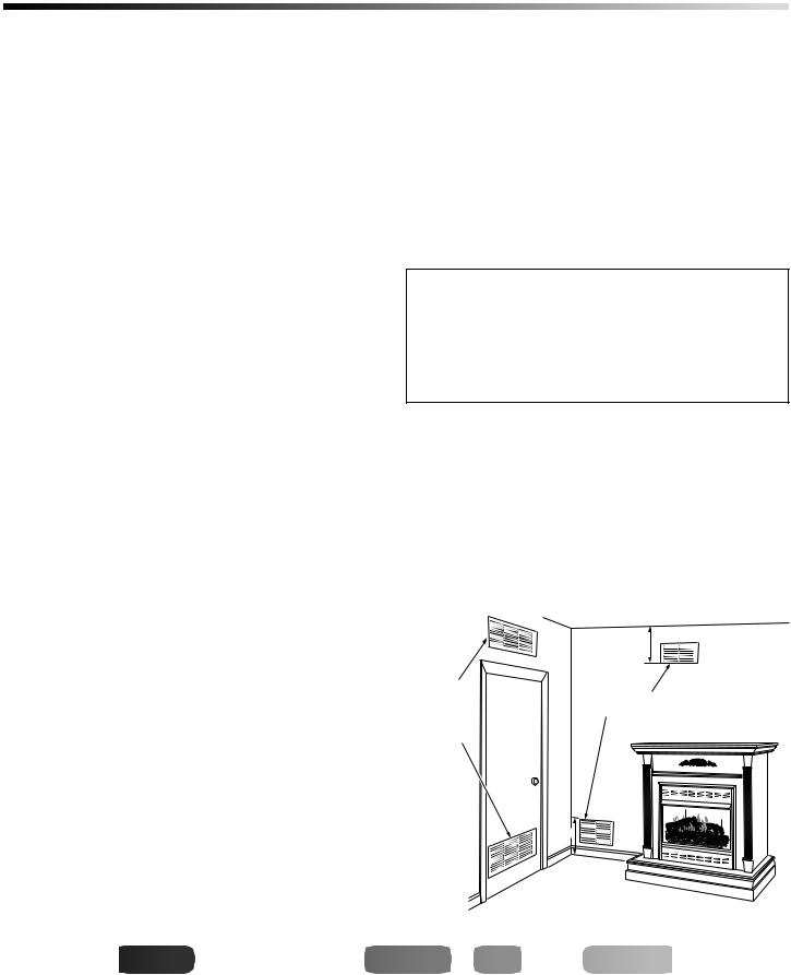
This fresh air would come from an adjoining unconfined space. When ventilating to an adjoining unconfined space, you must provide two permanent openings: one within 12" of the ceiling and one within 12" of the floor on the wall connecting the two spaces (see options 1 and 2, Figure 3). You can also remove door into adjoining room (see option 3, Figure 3). Follow the National Fuel Gas Code, ANSI Z223.1/NFPA 54, Section 5.3, Air for Combustion and Ventilation for required size of ventilation grills or ducts.
|
|
12" |
|
Ventilation |
|
Ventilation Grills |
|
Grills |
|
||
Into Adjoining |
Or |
Into Adjoining Room, |
|
Room, |
Option 2 |
||
Remove |
|||
Option 1 |
|
||
Door into |
|
||
|
|
||
|
Adjoining |
|
|
|
Room, |
|
|
|
Option |
|
|
|
3 |
|
|
|
|
12" |
Figure 3 - Ventilation Air from Inside Building (EFP33PR Shown)


 For
For


 visit
visit
 .
.

 .com
.com


108117-01G
AIR FOR COMBUSTION AND VENTILATION |
7 |
Ventilation Air (Cont.) |
|
INSTALLATION |
|
|
|
AIR FOR COMBUSTION AND VENTILATION
Continued
Ventilation Air From Outdoors
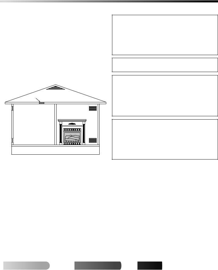
Provide extra fresh air by using ventilation grills or ducts. You must provide two permanent openings: one within 12" of the ceiling and one within 12" of the floor. Connect these items directly to the outdoors or spaces open to the outdoors. These spaces include attics and crawl spaces. Follow the National Fuel Gas Code, ANSI Z223.1/NFPA 54, Section 5.3, Air for Combustion and Ventilation for required size of ventilation grills or ducts.
IMPORTANT: Do not provide openings for inlet or outlet air into attic if attic has a thermostat-controlled power vent. Heated air entering the attic will activate the power vent.
Ventilated
Outlet Attic
Air
Outlet 

Air
To Attic
To
Crawl
Space
Inlet
Air
|
|
Inlet Air |
|
Ventilated |
|
|
|
|
|
|
Crawl Space |
|
|
|
|
|
|
|
|
Figure 4 - Ventilation Air from Outdoors (EFP33PR Shown)
INSTALLATION
NOTICE: This heater is intended for use as supplemental heat. Use this heater along with your primary heating system. Do not install this heater as your primary heat source. If you have a central heating system, you may run system’s circulating blower while using heater. This will help circulate the heat throughout the house. In the event of a power outage, you can use this heater as your primary heat source.
 WARNING: A qualified service person must install fireplace. Follow all local codes.
 WARNING: Never install the fireplace
•in a bedroom or bathroom
•in a recreational vehicle
•where curtains, furniture, clothing, or other flammable objects are less than 42 inches from the front, top, or sides of the fireplace
•in high traffic areas
•in windy or drafty areas
 CAUTION: This fireplace creates warm air currents. These currents move heat to wall surfaces next to fireplace. Installing fireplace next to vinyl or cloth wall coverings or operating fireplace where impurities (such as, but not limited to, tobacco smoke, aromatic candles, cleaning fluids, oil or kerosene lamps, etc.) in the air exist, may discolor walls or cause odors.
Note: Your fireplace is designed to be used in zero clearance installations. Wall or framing material can be placed directly against any exterior surface on the rear, sides, or top of your fireplace, except where standoff spacers are integrally attached. If standoff spacers are attached to your fireplace, these spacers can be placed directly against wall or framing materials.
Use the dimensions shown for rough openings to create the easiest installation (see Built-In Fireplace Installation, pages 19 and 20).
IMPORTANT: Vent-free heaters add moisture to the air. Although this is beneficial, installing fireplace in rooms without enough ventilation air may cause mildew to form from too much moisture. See Air for Combustion and Ventilation, pages 5 through 7.
IMPORTANT: Make sure the fireplace is level. If fireplace is not level, log set will not work properly.
 For more

 visit www.

 .com
.com


108117-01G
INSTALLATION
8 Check Gas Type
Electrical Hookup
Installation Clearances
Installation Sequence
Removing Fireplace Screen And Floor Assembly
INSTALLATION
Continued
CHECK GAS TYPE
Use the correct gas type (natural or propane/LP) for your unit. If your gas supply is not correct, do not install fireplace. Call dealer where you bought fireplace for proper type fireplace.
ELECTRICAL HOOKUP
This fireplace normally operates under 120 VAC/60 Hz line voltage. The electrical cord supplied with your fireplace is five feet in length. You must locate fireplace within reach of a 120 volt grounded electrical outlet. If not, you must install an electrical outlet within reach of the fireplace power cord. The GA3555 outlet accessory may be used for built-in applications.
INSTALLATION CLEARANCES
 WARNING: Maintain the minimum clearances. If you can, provide greater clearances from floor, ceiling, and adjoining wall.
Carefully follow the instructions below. This will ensure safe installation.
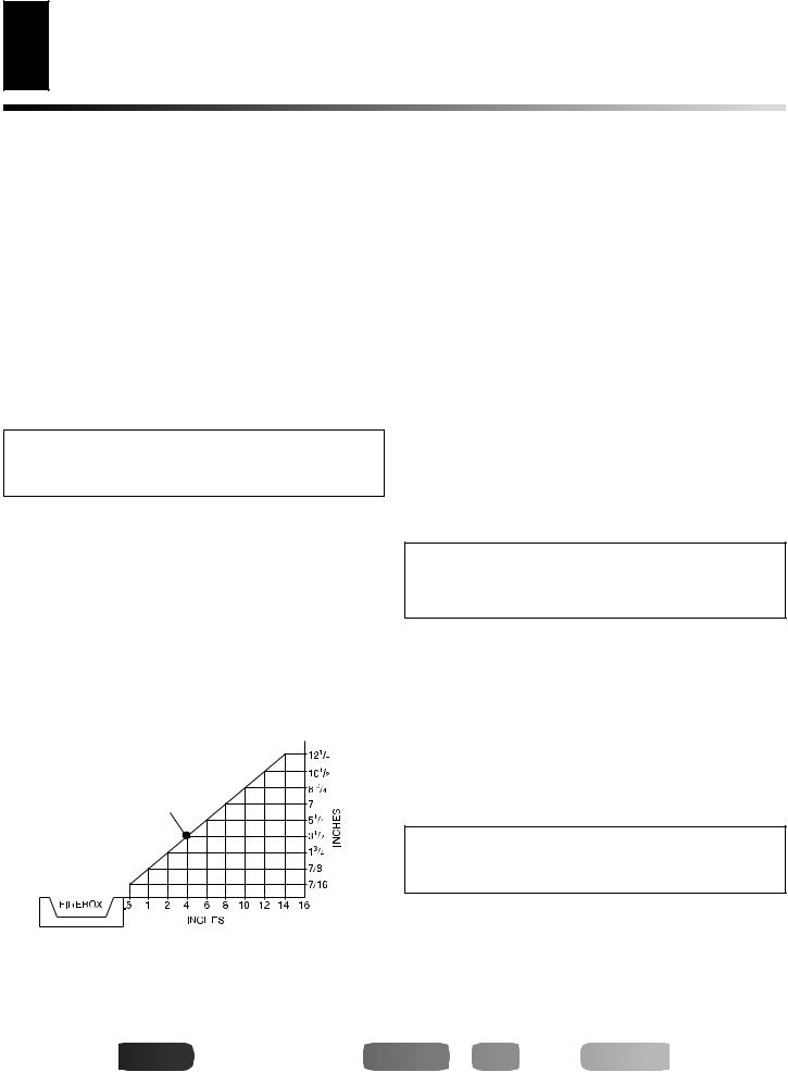
Minimum Clearances For Side Combustible
Material, Side Wall, and Ceiling
A.Clearances from the side of the fireplace cabinet to any combustible material and wall should follow diagram in Figure 5.
Example: The face of a mantel, bookshelf, etc. is made of combustible material and protrudes 3 1/2" from the wall. This combustible material must be 4" from the side of the fireplace cabinet (see Figure 5).
B.Clearances from the top of the fireplace opening to the ceiling should not be less than 42 inches.
Example |
* |
*Minimum 16 inches from Side Wall
Figure 5 - Minimum Clearance for Combustible to Wall
INSTALLATION SEQUENCE
After unpacking fireplace (see Unpacking, page 4), we suggest that you install your fireplace system in the following sequence:
1.Removal of fireplace floor assembly (required)
2.Electrical connections for power cord (required)
3.Relocating wall switch (optional)
4.Installing blower accessory (optional)
5.Connecting fireplace to gas supply (required)
6.Checking gas connections (required)
7.Firebox installation, conventional or built-in (required)
8.Installing brass perimeter trim (optional)
9.Installing fireplace hood (required)
10.Installing logs (required)
11.Installing fireplace screen (required)
Use the following instructions to complete each step.
REMOVING FIREPLACE SCREEN AND FLOOR ASSEMBLY
NOTICE: Shutoff gas supply and disconnect heater from gas supply if installing blower into previously installed fireplace. Contact a qualified service person to do this.
1.Remove fireplace screen. Remove two screws that hold fireplace screen in place for shipping. These screws are located near top of screen. Discard screws. Lift fireplace screen up and pull out to remove.
2.If logs are installed, carefully remove the logs and set aside, noting the properly mounted location of each.
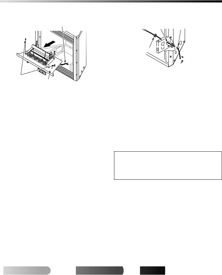
3.Remove screws that attach fireplace floor assembly to fireplace. Open lower louver door. Carefully lift up fireplace floor assembly and remove from fireplace, taking care to pull flexible gas line through the access holes (see Figure 6, page 9). Note: Be careful of all wires on underside of log base.
 CAUTION: Do not pick up fireplace floor assembly by burners. This could damage burners. Only handle base by grates.


 For
For


 visit
visit
 .
.

 .com
.com


108117-01G
INSTALLATION |
9 |
Removing Fireplace Screen And Floor Assembly (Cont.) |
|
Electrical Connections for Power Cord |
|
Relocating Wall Switch |
|
|
|
INSTALLATION
Continued
Flexible Gas Line
Screws
Fireplace Floor
Assembly
Figure 6 - Removing Fireplace Floor Assembly (VTGF33N/PR
Shown)
ELECTRICAL CONNECTIONS FOR POWER CORD
This fireplace operates on 120 VAC, 60 Hz power. An electrical power cord is supplied with this unit.
For Mantel Installation
1.Determine from which side of the fireplace the power cord will exit. Locate the 1.5" diameter hole near the center of floor support bracket on appropriate side of lower cavity (see Figure 7).
2.Locate power cord. Remove wire tie or tape holding plug end of power cord.
3.Power cord has 2 plastic hole bushings threaded onto it. Route cord's 3-prong plug through the 1.5" diameter hole in appropriate floor support bracket.
4.Push first plastic bushing completely through hole. Squeeze bushing as needed to do this.
5.Install the second plastic bushing into the hole in the floor support bracket by snapping into place.
6.Route the 3-prong plug through the 1.5" hole in fireplace outer casing.
7.Install the first plastic bushing into this hole by snapping into place.
8.After you have connected to gas supply and checked your gas connections (see pages 15 through 18), plug power cord into any convenient 3-prong grounded wall receptacle near fireplace.
For Recessed Installation
If an outlet is not installed in fireplace, install model GA3555 - Outlet Kit with Cover. This kit will supply a convenient 3-prong grounded electrical outlet for power. Refer to installation manual provided with this optional accessory for instructions on wiring. Note: A qualified installer must make all electrical connections.
Hole in Floor |
Hole in Outer |
Support Bracket |
Casing |
Bushings 

 Power Cord
Figure 7 - Routing Power Cord
RELOCATING WALL SWITCH
Note: The decorative wall switch plate supplied is white. The wall switch plate may be painted to match your decor.
The push-button switch and decorative wall plate assembly supplied with your fireplace is pre-mounted at the factory in the lower cavity of the fireplace. You may relocate this switch/plate assembly to a more convenient location such as the side of your mantel or directly onto the wall near the fireplace. To mount the wall switch/ plate assembly, you must first cut openings in the mantel or wall where the switch will be located.
Note: If you choose to relocate the wall switch, do so before final installation into a mantel or recessing into a wall. If you are installing an optional blower accessory, install it at the same time you relocate the wall switch.
 CAUTION: The wall switch must never be mounted directly above the fireplace where heat may damage it. If you relocate wall switch from lower fireplace cavity, it must be mounted either on side wall of mantel or on wall to side of fireplace.
For Recessed Installation
If fireplace is to be recessed into a wall (see Built-In Fireplace Installation, pages 19 and 20), we recommend mounting wall switch to left side of fireplace. The wall switch should be mounted approximately 12" from left edge of fireplace, and less than 60" from the floor. IMPORTANT: Do not locate wall switch directly in front of wall stud - there must be room behind wall board for wires from switch. If you choose to locate wall switch to right side of fireplace, the length of the cord restricts you to less than 6" from right edge of fireplace and less than 48" from floor.
 For more

 visit www.

 .com
.com


108117-01G
10 |
INSTALLATION |
Relocating Wall Switch (Cont.) |
INSTALLATION
Continued
For Mantel Installation
If fireplace is to be installed into a mantel, (see Conventional Fireplace Installation, pages 18 and 19) the wall switch may be mounted on either side of the mantel, facing to the side. Do not locate wall switch anywhere on the front face of the mantel.
 CAUTION: Be careful of gas lines and wiring when moving floor.
1.Determine the new location for the wall switch. The wires attached to switch are six feet long.
2.Remove 2 screws securing plastic wall plate to bracket in fireplace lower cavity. Save screws.
3.Remove wire tie holding coiled wire attached to wall switch (see Figure 8).
4.Remove wall switch/plate assembly from bracket.
5.Carefully pass wall plate and cord through large elongated hole in rear of either left or right floor support bracket, depending on desired location of switch. Pass wall plate and cord through 1.5" diameter hole in side of fireplace outer casing (see Figure 9).
6.Pull wall plate and cord from fireplace making sure wall switch/ plate assembly will reach desired mounting location without straining cord assembly.
If you are mounting wall switch to a wall, continue reading. If you are mounting your wall switch to the side of the mantel, see page 11.
 CAUTION: Do not apply excessive pull on cord.
Burner |
|
Firebox |
Outlet |
Wire Tie |
Bottom |
Tube |
|
|
Gas Control Valve |
Switch with |
|
Wall Plate |
||
|
||
Figure 8 - Relocating Switch and Wall Plate |
|
|
Hole in Outer |
|
|
Casing |
Hole in |
|
|
Floor |
|
|
Support |
|
|
Bracket |
Wall Switch/Plate Assy
Figure 9 - Routing Wall Switch/Plate Through Fireplace for Relocation
Mounting Wall Switch to Wall for Recessed Fireplace
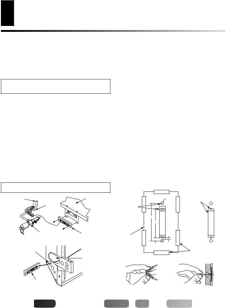
7.Create three openings on wall according to Template 1, page 45. This is best done by making a pattern to work with on your wall. Carefully cut page 45/46 from manual and tape paper template vertically onto wall at preferred location. Pierce the paper at the centers of the 2 holes with a nail or sharp pencil, leaving a mark on the wall. Do the same at centers of the four circles near the corners of the rectangle.
8.Remove paper template from wall.
9.Drill 3/8" holes at each mark.
10.Using a straight edge and pencil, connect the outer edges of the 4 holes for the rectangle (see Figure 10). This will give you cutting lines for the rectangle you will cut in the wall.
11.Using a keyhole saw, hack saw blade, drill, file, or other suitable tool, carefully cut out the rectangular opening. Note: The corners of the rectangle may be round. IMPORTANT: Do not exceed the size of the rectangle on template.
12.From inside the recessed opening for the fireplace, carefully pass switch/plate assembly through the rectangular opening to the outside of the wall.
13.Using wall anchors supplied in hardware package, fold wall anchor as shown in Figure 11.
14.Insert wall anchor, wings first, into hole. Tap anchor flush to wall.
15.For thin walls (1/2" or less), insert red key into wall anchor. Push red key to “pop” open anchor wings. See Figure 12. IMPORTANT: Do not hammer key! For thick walls (over 1/2" thick), do not pop open wings.
|
3/8" Diameter |
Cutting |
|
2 Holes |
Lines |
Make Marks |
3/4" |
|
at Centers |
|
|
of Holes |
4 3/4" |
|
|
|
|
|
3 3/4" |
|
Template |
|
|
from This |
3/8" |
|
3/16" |
|
|
Manual |
|
|
|
|
Tape |
Figure 10 - Using Template for Wall Switch Installation
Figure 11 - Folding Anchor Figure 12 - Popping Open Anchor Wings for Thin Walls


 For
For


 visit
visit
 .
.

 .com
.com


108117-01G
INSTALLATION |
11 |
Relocating Wall Switch (Cont.) |
|
Installing Variable Speed Blower Accessory |
|
|
|
INSTALLATION
Continued
16.Position switch/plate assembly vertically over wall openings with decal lettering upright (see Figure 13).
17.Insert mounting screws, removed in step 2 of Relocating Wall Switch on pages 9 and 10, through holes in wall plate and into wall anchors.
18.Tighten screws until wall plate is firmly attached to wall. Do not overtighten.
Opening in
Wall or
Mantel Wall
Wall Plate/
 Switch
Screws
Figure 13 - Securing Wall Switch
Mounting Wall Switch to Side of Mantel
7.Create three openings in the mantel wall according to Template 2, page 45. This is best done by making a pattern to work with on the mantel. Carefully cut page 45/46 from manual and tape paper template vertically onto mantel wall at preferred location. Pierce the paper at the centers of the 2 holes with a nail or sharp pencil, leaving a mark on the wall. Do the same at centers of the four circles near the corners of the rectangle.
8.Remove paper template from mantel wall.
9.Drill 1/8" pilot holes at each mark for top and bottom screw holes. Drill 3/8" holes at each mark for centers of four circles near corners of rectangle.
10.Using a straight edge and pencil, connect the outer edges of the 4 holes for the rectangle (see Figure 10, page 10). This will give you cutting lines for the rectangle you will cut in the mantel wall.
11.Using a keyhole saw, hack saw blade, drill, file, or other suitable tool, carefully cut out the rectangular opening. Note: The corners of the rectangle may be round. IMPORTANT: Do not exceed the size of the rectangle on template.
12.Carefully pass switch/plate assembly through rectangular opening from inside mantel (see Figure 13).
13.Position switch/plate assembly vertically over opening with decal lettering upright. Make sure wires freely pass through wall without binding. Align holes in wall plate with 1/8" pilot holes in mantel wall.
14.Drive mounting screws, removed in step 2 of Relocating Wall Switch on pages 9 and 10, through wall plate holes and into pilot holes in mantel wall.
15.Tighten screws until wall plate is firmly attached to mantel. Do not overtighten.
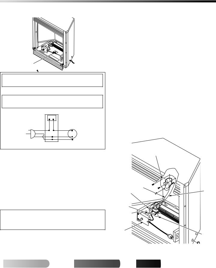
INSTALLING VARIABLE SPEED BLOWER ACCESSORY
NOTICE: Shut off gas supply and disconnect heater from gas supply if installing blower into previously installed fireplace. Contact a qualified service person to do this.
1.If fireplace screen and floor are still installed, see Removing Fireplace Screen and Floor Assembly, page 8.
2.Attach the power cord to the blower motor by firmly pushing the two female terminals at the end of the power cord onto the two spade terminals on the blower motor.
3.Attach green ground wire from power cord to blower housing using screw provided (see Figure 14). Tighten screws securely.
4.Place the blower against lower rear wall of firebox outer wrapper with the exhaust port directed upward. Align the holes in top mounting tabs of blower with holes in wall of wrapper (see Figure 14). Using 2 screws provided, mount blower and tighten screws securely.
Blower
Lower Rear
Wall of
 Firebox
Screws
Exhaust

 Port
Port
Top
Mounting
Tab
Screw
Green Ground Wire
Figure 14 - Mounting Blower to Firebox (VTGF33NR/VTGF33PR Shown)
 For more

 visit www.

 .com
.com


108117-01G
12 |
INSTALLATION |
Installing Variable Speed Blower Accessory (Cont.) |
INSTALLATION
Continued
5.Be certain that all wire terminals are securely attached to ter10. Peel off backing paper and stick supplied wiring diagram de-
minals on blower motor and that the screw retaining the green ground wire is tight.
6.Place control knob provided on plastic control shaft of speed control.
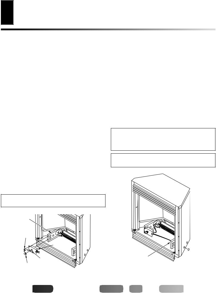
7.Mount the speed control on the front leg of the left floor support bracket using 2 screws provided (see Figure 15).
8.Plug in blower power cord.
a.If your fireplace system is installed as a freestanding unit with an accessory mantel, determine whether the power cord will exit the left side or the right side of the firebox. Install 1 plastic bushing provided into the 1.5" hole in the floor support bracket on the exit side (see Figure 16). Install the second plastic bushing provided into the 1.5" hole in the outer casing through which the power cord will exit. Route power cord through both plastic bushings and plug the power cord into a properly grounded 3-prong wall receptacle near the firebox.
b.If your fireplace system installation is recessed and if an outlet is not installed in your fireplace, you must install the GA3555 Outlet kit with cover in your fireplace which will supply a convenient 3-prong grounded electrical outlet for your blower. Refer to the installation manual provided with the model GA3555 accessory for instructions on wiring the duplex outlet.
Note:A qualified installer must make all electrical connections.
9.Check to make sure that all electrical cords are completely clear of the blower wheel and that there are no other foreign objects in blower wheel. Turn blower on and check for operation. Turn blower off by rotating knob fully counterclockwise before continuing.
 CAUTION: Never touch the blower wheel while in operation.
Left Floor
Support
Bracket
Screws
Speed
 Control
|
Control |
Control Knob |
Shaft |
|
cal near center of firebox bottom (Figure 17, page 13).
11.If gas connections have been made and checked, replace fireplace floor assembly. Feed flexible gas supply line into fireplace base area while replacing fireplace floor assembly. Make sure the entire flexible gas line is in fireplace base area.
IMPORTANT: Do not pick up fireplace floor assembly by burners. This could damage burners. Only handle base by grates. Note: Be careful of all wires and components on underside of floor assembly.
12.Reattach fireplace floor assembly with screws removed in step 3 of Removing Fireplace Screen and Floor Assembly, page 8.
Note: Discard the remaining hardware items. After assembly, make sure all wires are completely clear of blower wheel.
13.Install logs (see Installing Logs, pages 21 through 23) and fireplace screen (see Installing Screen, page 24).
 WARNING: Failure to position the parts in accordance with supplied diagrams or failure to use only parts specifically approved with this heater may result in damage or personal injury.
 WARNING: A qualified service person must connect fireplace to gas supply. Follow all local codes.

 Plastic
Right Floor 
 Bushing
Support Bracket
Figure 15 - Attaching Speed Control to Firebox (VTGF33NR/ VTGF33PR Shown)
Figure 16 - Installing Plastic Bushing for Power Cord (VTGF33NR/ VTGF33PR Shown)


 For
For


 visit
visit
 .
.

 .com
.com


108117-01G
INSTALLATION |
13 |
Installing Variable Speed Blower Accessory (Cont.) |
|
Installing Thermostatic Blower Accessory |
|
|
|
INSTALLATION
Continued
Wiring
Diagram 
 WARNING: Never attempt to service heater while it is plugged in, operating, or hot. Burns and electrical shock could result. Only a qualified service person should service or repair heater.
If any of the original wire as supplied with the appliance must be replaced, it must be replaced with 105°C wire or it’s equivalent.
 WARNING: Label all wires prior to disconnection when servicing controls.Wiring errors can cause improper and dangerous operation.Verify proper operation after servicing.
|
|
Variable |
|
|
|
|
Fan Switch |
|
|
|
|
Off |
On |
|
110/115 |
|
Black |
Black |
Blower |
V.A.C. |
Black |
|
|
Motor |
|
|
|
Black |
|
|
Green |
|
|
|
|
|
White |
White |
||||||
120 Vac. 60 Hz. . 78 Amps |
|
|
|
|
|
|
|||
|
|
|
|
|
|
||||
101584-05 |
|||||||||
DESA International, Bowling Green, KY |
|||||||||
Figure 17 - Location of Wiring Diagram Decal 3" from Blower (VTGF33NR/VTGF33PR Shown)
Operating the Blower
Light your gas appliance with the blower off. After about 15 minutes, turn the blower on to deliver heated air at the top louvers. The blower features a variable control which allows you to select the speed you desire. Note: Periodically check the louvers of the firebox and remove any dust, dirt, or other obstructions.
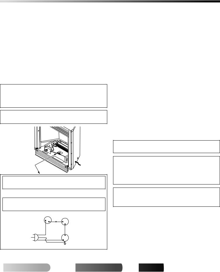
INSTALLING THERMOSTATIC BLOWER ACCESSORY
NOTICE: Shut off gas supply and disconnect heater from gas supply if installing blower in previously installed fireplace. Contact a qualified service person to do this.
1.If fireplace screen and floor are still installed, see Removing Fireplace Screen and Floor Assembly, page 8.
2.Using screw provided, attach green ground wire from speed control cord to blower housing. Tighten screw securely (see Figure 18).
3.Place the blower against lower rear wall of firebox outer wrapper with the exhaust port directed upward. Align the holes in top mounting tabs of blower with holes in wall of wrapper (see Figure 19, page 14). Using two #8 screws provided, mount blower and tighten screws firmly.
4.Remove the three screws (do not discard) and cover plate from center of firebox wrapper rear wall. Discard this cover plate (see Figure 18).
5.Mount the supplied thermostatic switch and cover assembly into firebox wrapper wall. Do this by feeding terminal ends of wire harness into the hole. Allow wires to fall to bottom of firebox cavity (see Figure 18).
6.Using three screws from step 7, attach switch and cover assembly to firebox wrapper rear wall. Tighten screws firmly (see Figure 18).
7.Firmly attach red wire from the thermostatic switch and cover assembly to either of the terminals on the blower motor (see Figure 18).
8.Firmly attach black wire from speed control cord to blue wire from thermostatic switch and cover assembly (see Figure 18).
9.Firmly attach white wire from speed control cord to remaining terminal on blower motor (see Figure 18).
Thermostatic Switch
and Cover Assembly
Blue |
|
Black Wire |
Red |
Wire |
Wire |
White |
|
Wire |
|
Speed |
|
Control |
Green |
|
Wire |
Figure 18 - Installing Switch and Cover Assembly, and Speed Control (VTGF33NR/VTGF33PR Shown)
 For more

 visit www.

 .com
.com


108117-01G

14 |
INSTALLATION |
Installing Thermostatic Blower Accessory (Cont.) |
INSTALLATION
Continued
10.Place control knob provided on plastic control shaft of speed control (see Figure 20).
11.Mount the speed control onto the front leg of the left floor support bracket using 2 screws provided (see Figure 20).
 WARNING: Failure to connect all wires properly as indicated may cause electrical short circuit or personal injury. A qualified electrician should check that all connections are made properly.
12.Plug in blower power cord.
a.If your firebox is installed as a freestanding unit with an accessory mantel, determine whether the power cord will exit the left side or the right side of the firebox. Install one plastic bushing provided into the 1 1/2" hole in the floor support on the exit side. Install the second bushing provided into the 1 1/2" hole in the outer casing through which the power cord will exit (see Figures 21 and 22). Route power cord through plastic bushings and plug the power cord into a properly grounded three-prong wall receptacle near the firebox.
b.If your fireplace system installation is recessed and if an outlet is not installed in your fireplace, you must install the GA3555 Outlet kit with cover in your fireplace which will supply a convenient 3-prong grounded electrical outlet for your blower. Refer to the installation manual provided with the model GA3555 accessory for instructions on wiring the duplex outlet.
Note:A qualified installer must make all electrical connections.
Blower
Lower
Rear Wall
of Firebox
#8 Screws
Exhaust
 Port
Port
Top
 Mounting
Tab
13.Check to make sure that the power cord and all wires are completely clear of the blower wheel and that there are no other foreign objects in blower wheel.
 CAUTION: Never touch the blower wheel while in operation.
14.Peel off backing paper and stick supplied wiring diagram decal near center of firebox bottom (see Figure 23, page 15).
Floor
Support
Bracket
Speed
Control
Screws
Control Knob
Figure 20 - Attaching Speed Control (VTGF33NR/VTGF33PR
Shown)
Right Floor |
Plastic |
Support Bracket |
Bushing |
Figure 21 - Installing Plastic Bushing for Power Cord (Right Side Exit Shown) (VTGF33NR/VTGF33PR Shown)
Bushing |
Plastic |
|
Bushing |
||
Location for |
||
|
||
Freestanding |
Bushing Location |
|
Installation |
||
|
for Recessed |
|
|
Installation |
Figure 19 - Mounting Blower to Firebox (VTGF33NR/VTGF33PR |
Figure 22 - Installing Bushings (Left Side Exit shown) |
|
Shown) |
||
(VTGF33NR/VTGF33PR Shown) |
||
|


 For
For


 visit
visit
 .
.

 .com
.com


108117-01G
INSTALLATION |
15 |
Installing Thermostatic Blower Accessory (Cont.) |
|
Installing Gas Piping to Fireplace Location |
|
|
|
INSTALLATION
Continued
15.If gas connections have been made and checked, replace fireplace floor assembly in fireplace. Feed flexible gas supply line into fireplace base area while replacing fireplace floor assembly. Make sure the entire flexible gas line is in fireplace base area. IMPORTANT: Do not pick up fireplace floor assembly by burners. This could damage burners. Only handle base by grates. Note: Be careful of all wires and components on underside of floor assembly.
16.Reattach fireplace floor assembly with screws removed in step 3 of Removing Fireplace Screen and Floor Assembly, page 8.
Note: Discard the remaining hardware items. After assembly, make sure all wires are completely clear of blower wheel.
17.Install logs (see Installing Logs, pages 21 through 23) and fireplace screen (see Installing Screen, page 24).
 WARNING: Failure to position the parts in accordance with supplied diagrams or failure to use only parts specifically approved with this heater may result in damage or personal injury.
 WARNING: A qualified service person must connect fireplace to gas supply. Follow all local codes.
If any of the original wire as supplied with the appliance must be replaced, it must be replaced with 105˚C wire or it's equivalent.
Operating the Blower
After final installation of your fireplace, light your gas appliance with the blower off. After about 15 minutes, turn the blower on to deliver heated air at the top louvers. The blower features a variable control which allows you to select the speed you desire. In the OFF position, the blower will not operate. In the ON position, the blower will start when the thermostat senses a sufficient increase in firebox temperature (approximately 10 to 20 minutes depending on heat setting).
Your gas logs and thermostat blower will not turn on and off at the same time. The fireplace may run for several minutes before the blower turns on. After the heater modulates to the pilot position, the blower will continue to run. The blower will shut off after the firebox temperature decreases.
It is safe to operate fireplace with blower turned off. However, the blower helps distribute heated air from the fireplace.
Note: Periodically check the louvers of the firebox and remove any dust, dirt, or other obstructions.
Wiring
Diagram
 WARNING: Never attempt to service heater while it is plugged in, operating, or hot. Burns and electrical shock could result. Only a qualified service person should service or repair heater.
If any of the original wire as supplied with the appliance must be replaced, it must be replaced with 105°C wire or it’s equivalent.
 WARNING: Label all wires prior to disconnection when servicing controls. Wiring errors can cause improper and dangerous operation. Verify proper operation after servicing.
Variable
Fan Switch Fan Switch
(N.O.)
Off 1 |
2 Black |
|
|
On |
Blue |
|
|
Red
110/115
V.A.C.
Black
Green |
Blower |
White |
Motor |
120 Vac. 60 Hz. .90 Amps
DESA International, Bowling Green, KY
Figure 23 - Location of Wiring Diagram Decal 3" from Blower (VTGF33NR/VTGF33PR Shown)
INSTALLING GAS PIPING TO FIREPLACE LOCATION
 WARNING: A qualified service person must connect fireplace to gas supply. Follow all local codes.
 WARNING: For propane/LP units, never connect fireplace directly to propane/LP supply. This fireplace requires an external regulator (not supplied). Install the external regulator between the heater and propane/LP supply.
 WARNING: For natural gas units, never connect fireplace to private (non-utility) gas wells. This gas is commonly known as wellhead gas.
 For more

 visit www.

 .com
.com


108117-01G
 Loading...