


Desa CD36M, CD42M-A, CD32M User Manual
DIRECT-VENT FIREPLACE
OWNER’S OPERATION AND
INSTALLATION MANUAL
For more information, visit www.desatech.com
For more information, visit www.desatech.com
CD32M (-1)(-2), CD36M (-A1)(-A2), CD42M-A
WARNING: If the information in this manual is not
followed exactly, a fire or explosion may result causing property damage, personal injury, or loss of life.
FOR YOUR SAFETY
Do not store or use gasoline or other flammable
vapors and liquids in the vicinity of this or any other
appliance.
FOR YOUR SAFETY
WHAT TO DO IF YOU SMELL GAS
• Do not try to light any appliance.
• Do not touch any electrical switch
• Do not use any phone in your building.
• Immediately call your gas supplier from a
neighbor’s phone. Follow the gas supplier’s
instructions.
• If you cannot reach your gas supplier, call the fire
department.
This fireplace is manufactured for Stylecrest Inc. under the Coleman brand name by DESA.
This book is valuable. In addition to instructing you on
how to install and maintain your appliance, it also contains information that will enable you to obtain replacement parts or optional accessory items when needed.
Keep it with your other important papers.
WARNING: Improper installation, adjustment, alteration, service, or maintenance can cause injury or property
damage. Refer to this manual for correct installation and operational procedures. For assistance or additional information consult a qualified installer,
service agency, or the gas supplier.
WARNING: This direct-vent gas fireplace is intended for use with natural
or propane/LP gas only. Do not attempt to burn any solid fuels in this
appliance.
SAVE THIS BOOK
This fireplace may be installed as an OEM installation in a manufactured (mobile) home and
must be installed in accordance with the manufacturers instructions and the
Home Construction and Safety Standard, Title 24 CFR, Part 3280
Mobile Home Standard, CAN/CSA Z240 MH Series
the type(s) of gas indicated on the rating plate. A conversion kit is supplied with the fireplace.
Save this manual for future reference.
Save this manual for future reference.
, in Canada. This fireplace is only for use with
in the United States or the
Manufactured
TABLE OF CONTENTS
INTRODUCTION
2
Before You Begin
TABLE OF CONTENTS
INTRODUCTION......................................................................... 2
SELECTING LOCATION............................................................. 3
PRE-INSTALLATION PREPARATION ........................................ 3
INSTALLATION ........................................................................... 6
BURNER FLAME ADJUSTMENT..............................................11
OPERATING FIREPLACE ........................................................ 12
CONVERTING FIREPLACE FROM NATURAL GAS
TO PROPANE/LP GAS ........................................................ 13
INTRODUCTION
TROUBLESHOOTING .............................................................. 15
ILLUSTRATED PARTS BREAKDOWN AND PARTS LIST....... 16
SPECIFICATIONS .................................................................... 20
WIRING DIAGRAM ................................................................... 20
OWNER’S REGISTRATION FORM .......................................... 21
ACCESSORY AND REPLACEMENT PARTS........................... 23
WARNING: This product contains and/or generates
chemicals known to the State of California to cause
cancer or birth defects, or other reproductive harm.
Models CD32M sereies, CD36M-A series and CD42M-A are heat
circulating gravity direct-vent fireplaces with sealed combustion
chamber. These fireplaces use millivolt gas control valve and
millivolt ignition system.
These fireplaces are convertible with the standard setup as natural
gas. Conversion may be performed by the O.E.M. mobile home
builder or by a qualified service person on-site. If you are uncertain
as to what gas your unit is equipped for, please check the rating plate
located inside of the appliance opening or consult your mobile home
supplier or your local distributor of DESA/Coleman products.
NOTICE: Check local building codes for area requirements before installing this appliance.
BEFORE YOU BEGIN
Before beginning the installation of your appliance, read these
instructions through completely.
This DESA/Col eman fireplace and its components are safe when
installed according to this installation manual and operated as recommended. Unless you use DESA/Coleman components designed and
tested for this fireplace system, YOU MAY CAUSE A SAFETY
HAZARD!
The DESA/Coleman warranty will be voided by, and DESA/
Coleman disclaims any responsibility for the following actions:
A) Modification to the fireplace, components, doors, blower, fans
or vent system.
B) Use of any component part not manufactured or approved by
DESA/Coleman in combination with a DESA/Coleman fireplace system.
Proper installation is the most important step in ensuring safe and
continuous operation of the fireplace. Consult the local building
codes as to the particular requirements concerned with the installation of all factory built fireplaces. This fireplace, when installed,
must be electrically grounded in accordance with local codes, or in
the absence of local codes, with the National Electrical Code, ANSI/
NFPA 70 or the Canadian Electrical Code, CSA C22.1.
The installation must conform with local codes or, in the absence of
local codes, with the National Fuel Gas Code, ANSI Z223.1 or the
Canadian Installation Code, CAN/CGA B149. This appliance complies with ANSI Z21.88-1998 and CSA 2.33-M98 as a VENTED
GAS FIREPLACE HEATER.
For more information, visit www.desatech.com
For more information, visit www.desatech.com
111916-01A
SELECTING LOCATION
PRE-INSTALLATION PREPARATION
Clearances to Combustibles
Mantel Clearances
3
3
SELECTING LOCATION
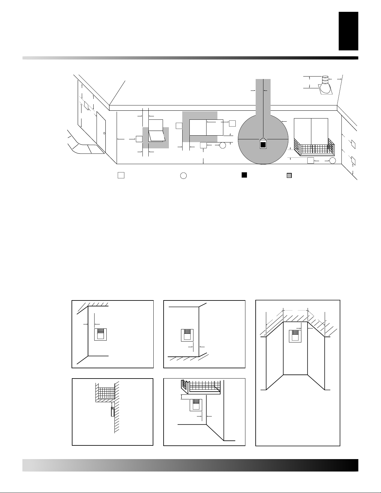
To determine the safest and most efficient location for your fireplace, consider the following guidelines:
1. The location must allow for proper clearances (see Figure 1).
2. Consider a location where the firepace would not be affected
by drafts, air conditioning ducts, windows or doors.
3. A location that avoids the cutting of joists or roof rafters makes
ventilation installation easier.
In selecting a location, the following precautions must be observed:
• Do not connect this appliance to a chimney system used for solid
fuel burning fireplace.
• Due to high temperatures, do not locate this appliance in high
traffic areas or near furniture and draperies.
• Never obstruct the openings of the appliance or flow of ventila-
tion air. Keep the control compartments accessible.
• Do not locate appliance close to where gasoline or other flam-
mable liquids may be stored. The appliance must be kept clear
and free from combustible materials.
• Do not use this appliance if any part has been under water. Imme-
diately contact a local service technician to examine the appliance and to replace any part(s) of the control ignition system and
other related components that have been submerged under water .
FULL
PROJECTION
CORNER
INSTALLATION
FLUSH
INSTALLATION
PRE-INSTALLATION
PREPARATION
CAUTION: Do not block required air spaces with
insulation or any other material. Do not obstruct the
effective opening of the appliance with any type of
facing material.
CLEARANCES TO COMBUSTIBLES
Minimum clearances to combustibles for the fireplace are:
• Back and Sides of Fireplace .................................................. 0"
• Floor ......................................................................................0"
• Perpendicular Wall................................................................ 6"
• Front ....................................................................................36"
• Top of Standoffs.................................................................... 0"
MANTEL CLEARANCES
Woodwork, such as wood trims, mantles, and other combustible
materials should be placed within the required clearance specified
in Figure 2.
Mantel Mantel From Top
Depth of Opening
(1) 14" (A) 16"
(2) 12" (B) 14"
1
2
A
B
C
D
E
3
4
5
6
7
F
G
(3) 10" (C) 12"
(4) 8" (D) 10"
(5) 6" (E) 8"
(6) 4" (F) 6"
Wall
(7) 2" (G) 4"
Figure 1 - Common Fireplace Locations
Flush installation is recommended where living space is limited.
Projected installation may be ideal for a new addition to an
existing finished wall.
Corner installation makes use of a space that may not normally be
used and provides a wider and more efficient range for radiant heat
transfer.
For more information, visit www.desatech.com
For more information, visit www.desatech.com
111916-01A
Top of Louver Opening
Figure 2 - Mantel Clearances
B
A
C
PRE-INSTALLATION PREPARATION
4
Vent Termination Clearances
Framing
PRE-INSTALLATION
PREPARATION
Continued
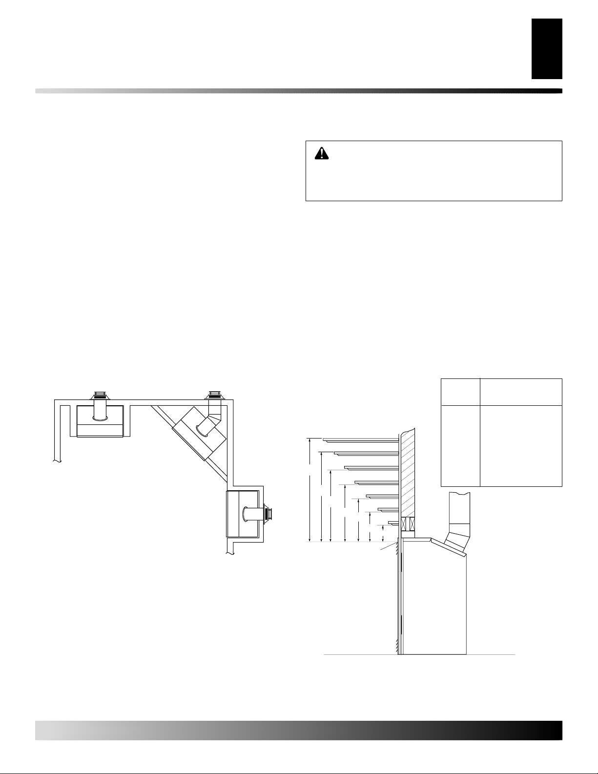
VENT TERMINATION CLEARANCES
The final position of your fireplace depends on the location of the
vent termination in relation to the clearances that must be observed
as shown in Figure 5 on page 5.
The vent system serves as the “chimney” as well as the combustion
air supply (air intake). The horizontal run must have a rise of 1/4"
(.6 cm) for every 12" (30.48 cm) of horizontal run towards the
termination. The maximum horizontal run depends on the vertical
rise from the fireplace adapter collar to the vent termination (see
table below).
VERTICAL HORIZONTAL
0 to 1 ft (30.48 cm)
1 ft (30.48 cm) to 4 ft (121.92 cm)
2 ft (60.96 cm) to 8 ft (243.84 cm)
3 ft (91.44 cm) to 12 ft (365.76 cm)
4 ft (121.92 cm) to 16 ft (487.68 cm)
5 ft (152.40 cm) to 15 ft (457.20 cm)
6 ft (182.88 cm) to 14 ft (426.72 cm)
7 ft (213.36 cm) to 13 ft (396.24 cm)
8 ft (243.84 cm) to 12 ft (365.76 cm)
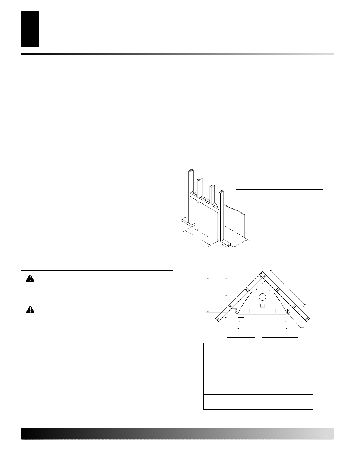
FRAMING
Once the final location has been determined, observing height clearances for vent termination, you may construct framing using dimensions shown in Figures 3 and 4, depending on your installation.
If the appliance is to be installed directly on carpeting, tile (other
than ceramic), or any combustible material other than wood flooring, the appliance must be installed on a metal or wood panel
extending the full width and depth of the appliance.
CD32M CD36M-A CD42M-A
A 32 3/8" 36 1/8" 40 1/8"
B 34 5/8" 41 1/4" 48 1/4"
C 19" 23 1/2" 25 5/8"
Figure 3 - Framing Dimension
WARNING: Never allow the vent to run downward
as this may cause excessive temperatures which
could cause a fire.
WARNING: Horizontal sections of this vent system require a minimum clearance of 2" from the top
of the pipe and 1" minimum to the sides and bottom.
Vertical sections of this system require a minimum
of 1" clearance to combustible materials on all sides
of the pipe.
For more information, visit www.desatech.com
For more information, visit www.desatech.com
B
A
E
CD32M CD36M-A CD42M-A
A 28 1/2" 35 3/4" 41 5/8"
B 13 5/8" 15" 21 5/8"
C 39 3/8" 49 5/8" 58 1/2"
D9 1/2" 10 3/8" 13 1/2"
E9 7/8" 13 3/4" 16 3/4"
F 34 1/2" 41 1/8" 48"
G 35 1/2" 42 1/8" 48 1/4"
H 54 3/8" 68 1/4" 81 1/2"
Figure 4 - Corner Installation
D
F
G
H
C
Nailing Tabs
111916-01A
PRE-INSTALLATION PREPARATION
Continued
D
E
V
B
L
V
A = clearance above grade, veranda, porch, deck, or balcony
[*12 inches (30.5cm) minimum]
B = clearance to window or door that may be opened
[12 inches (30.5cm) minimum]
C = clearance to permanently closed window [minimum 12 inches
(30.5cm) recommended to prevent condensation on window]
D = vertical clearance to ventilated soffit located above the terminal
within a horizontal distance of 24 inches (61cm) from the
center-line of the terminal [18 inches (45.7cm) minimum]
E = clearance to unventilated soffit [12 inches (30.5cm) minimum]
F = clearance to outside corner (see below)
G = clearance to inside corner (see below)
H = *not to be installed above a meter/regulator assembly within
36 inches (91.4cm) horizontally from the center-line of the regulator
vent shall not terminate directly above a side-walk or paved driveway which is located between two
single family dwellings and serves both dwellings*
only permitted if veranda, porch, deck or balconey is fully open on a minimum of 2 sides beneath the floor*
* as specified in CAN/SGA B149 (.1 or .2) Installation Codes (1991) for Canada or for U.S.A. installation follow
the current
Note: Local codes or regulations may require different clearances
Termination Clearances for Buildings with Combustible and Noncombustible Exteriors
Inside Corner
C
Fixed
Closed
F
TERMINATION CAP
Openable
V
B
National Fuel Gas Code, ANSI Z223.1
V
X
Outside Corner Recessed Location
Openable
V
B
A
AIR SUPPLY INLET
PRE-INSTALLATION PREPARATION
N
H
B
Fixed
Closed
J
V
B
X
G
I = clearance to service regulator vent outlet [*72 inches (182.9cm)
minimum]
J = clearance to non-mechanical air supply inlet to building or the
combustion air inlet to any other fireplace [*12 inches (30.5cm)
minimum]
K = clearance to a mechanical air supply inlet [*72 inches (182.9cm)
minimum]
L = clearance above paved side-walk or a paved driveway located on
public property [*84 inches (213.4cm) minimum]
M = clearance under veranda, porch, deck [*12 inches (30.5cm) minimum ]
N = clearance above a roof shall extend a minimum of 24 inches (61cm)
above the highest point when it passes through the roof surface and
any other obstruction within a horizontal distance of 18 inches (45.7cm)
G
GAS METER RESTRICTED AREA
I
M
V
(TERMINATION PROHIBITED)
N
X
K
5
5
G
V
G
V
A
A
Balcony with No Side Wall
G = Combustible 24" (61cm)
Noncombustible 18" (45.7cm)
A = 6" (15.2cm)
V
G
V
Figure 5 - Minimum Clearances for Vent Terminations
For more information, visit www.desatech.com
For more information, visit www.desatech.com
111916-01A
V
B = 6" (15.2cm)
B
Balcony with Perpendicular Side Wall
H
V
J
Combustible &
Noncombustible
H = 24" (61cm)
J = 20" (50.8cm)
D
C
V
C = Maximum depth of 48" (121.9cm) for
recessed location
D = Minimum width for back wall of
recessed location Combustible - 38" (96.5cm)
Noncombustible - 24" (61cm)
E = Clearance from corner in
recessed locationCombustible - 6" (15.2cm)
Noncombustible - 2" (5.1cm)
C
E
INSTALLATION
6
Venting Installation Precautions
Venting Installation
INSTALLATION
WARNING: Read all instructions completely and
thoroughly before attempting installation. Failure to
do so could result in serious injury, property damage
or loss of life. Operation of improperly installed and
maintained venting system could result in serious
injury, property damage or loss of life.
NOTICE: Failure to follow these instructions will void
the warranty.
VENTING INSTALLATION PRECAUTIONS
Consult local building codes before beginning the installation. The
installer must make sure to select the proper vent system for installation . Before installing vent kit, the installer must read this fireplace
manual and vent kit instructions.
Only a qualified service person should install venting system. The
installer must follow these safety rules:
• Wear gloves and safety glasses for protection
• Use extreme caution when using ladders or when on roof tops
• Be aware of electrical wiring locations in walls and ceilings
The following actions will void the warranty on your venting system:
• Installation of any damaged venting component
• Unauthorized modification of the venting system
• Installation of any component part not manufactured or approved
by DESA
• Installation other than as instructed by these instructions
WARNING: This gas fireplace and vent assembly
must be vented directly to the outside. The venting
system must NEVER be attached to a chimney serving a separate solid fuel burning appliance. Each gas
appliance must use a separate vent system. Do not
use common vent systems.
WARNING: Horizontal sections of this vent system require a minimum clearance of 2" from the top
of the pipe and 1" minimum to the sides and bottom.
Vertical sections of this system require a minimum
of 1" clearance to combustible materials on all
sides of the pipe.
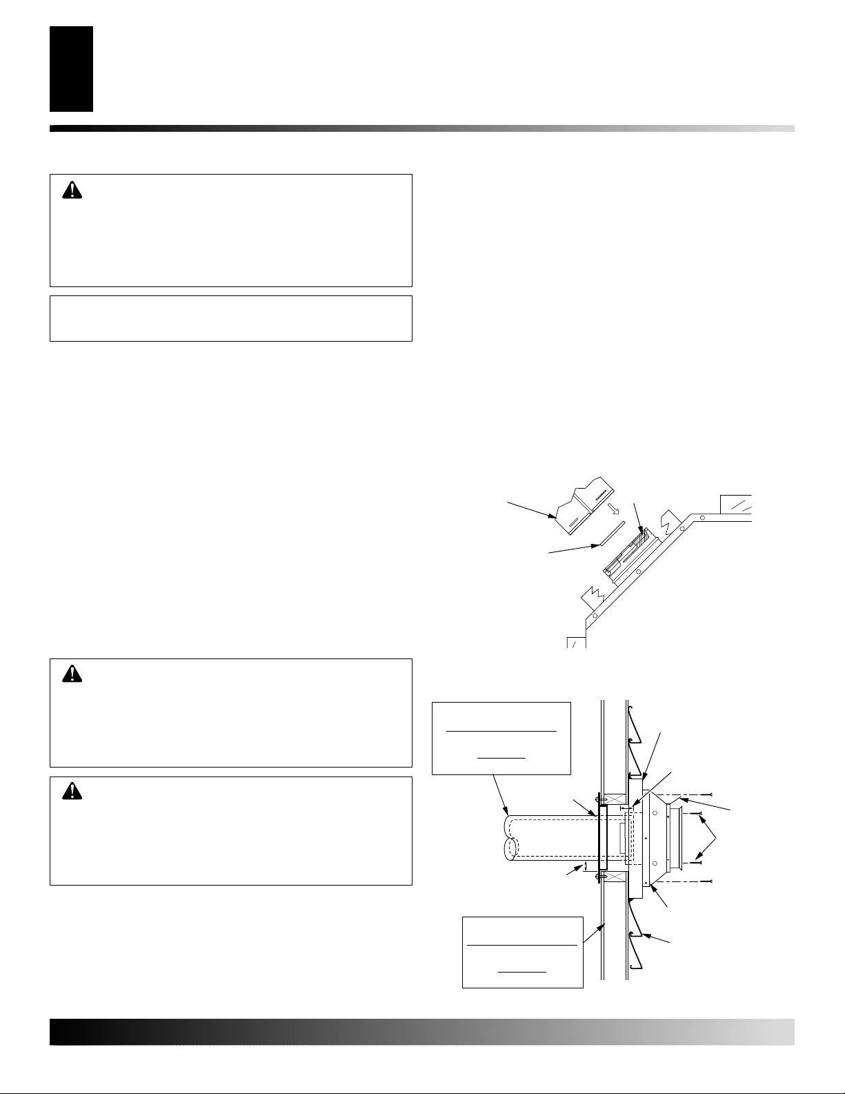
VENTING INSTALLATION
1. Install elbow to fireplace collar adapter located on back of the
unit at a 45° angle. Slide elbow over collar and twist to lock.
Check to insure proper connection (see Figure 6).
2. Continue to install remainder of pipe for desired installation.
Make sure each section is twist-locked securely.
3. When installation of vent pipe is complete, in stall vent termination. Depending on the location of your fireplace, you will
vent vertically or horizontally.
4. Allow 1" of pipe to protrude from internal wall, depending on
wall thickness. See Figure 7.
5. For horizontal installation, an optional siding standoff may be
installed between the vent cap and the exterior wall. Secure
horizontal vent cap to standoff. Secure standoff/vent cap assembly to wall (see Figure 7). Do not seal termination to vent
pipe. The vent termination must be removable for service pipe
inspection.
6. For vertical installation, a vertical termination is available. Also
for vertical venting application, install vertical flue restrictor
into inner collar of fireplace as shown in Figure 6.
When installing a length of pipe for vertical termination that is
over 3 ft., support the pipe every 3 ft. using metal wall straps.
Vertical to horizontal pipe must be kept at a 1 ft. to 4 ft. ratio
with a maximum run of no more than 20 ft.
Female Locking Lugs
Vertical Flue Restrictor
(For Vertical Venting
Application)
Figure 6 - Venting Installation
Direct-Vent Pipe
CD32M and CD36M-A
4 1/4" Inner and 7 1/4" Outer
CD42M-A
5" Inner and 8" Outer
Wall
Firestop
Maintain 1" Minimum Air
Space Around Outer Pipe
when Penetrating a Wall
Framed Openings
CD32M and CD36M-A
10" x 10"
CD42M-A
10 3/4" x 10 3/4"
Figure 7 - Vent Termination (Horizontal)
Male Locking
Lugs
Siding Standoff
(Optional)
Minimum Pipe
Overlap 1
Horizontal
Termination
(Vent Cap)
Exterior Wall with
Vinyl Siding
1
/4"
Deflector
Shield
Screws
For more information, visit www.desatech.com
For more information, visit www.desatech.com
111916-01A
INSTALLATION
Continued
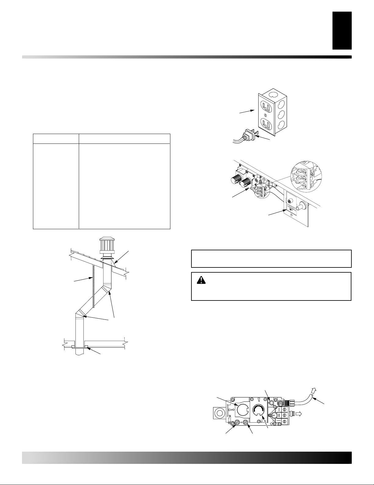
If an offset is necessary in the attic to avoid obstruction, it
is important to support the vent pipe every 3 ft. to avoid
excessive stress on the elbows and possible separation (see
Figure 8, page 7).
Clearances must be maintained between the roof and the termination. Refer to chart below.
INSTALLATION
Venting Installation (Con.)
Electrical Gookup and Remote Reeiver Diagram
Gas Supply Testing
Outlet Box
7
7
Roof Pitch Minimum Height Above Roof
Flat - 7/12 1 ft. (30.48 cm)
7/12 - 8/12 1 1/2 ft. (45.72 cm)
8/12 - 9/12 2 ft (60.96 cm)
9/12 - 10/12 2 1/2 ft (76.20 cm)
10/12 - 11/12 4 ft (121.92 cm)
11/12 - 14/12 5 ft (152.40 cm)
14/12 - 16/12 6 ft (182.88 cm)
16/12 - 18/12 7 ft (213.36 cm)
18/12 - 20/12 7 1/2 ft (228.60 cm)
20/12 - 21/12 8 ft (243.84 cm)
Roof Flashing
Wall Strap
45° Elbows
Ceiling Firestop
Figure 8 - Vertical Termination with Offset and Wall Strap
ELECTRICAL HOOKUP AND REMOTE
RECEIVER DIAGRAM
An outlet box with two receptacles (see Figure 9) has been supplied
for your convenience and is located inside on the lower right side of
the fireplace.
The remote control receiver is factory wired and connected to the
convertible gas valve as shown in Figure 10.
Three-prong Plug
Figure 9 - Duplex Outlet
H
T
P
T
H
T
P
T
F
F
O
N
Convertible
Gas Valve
L
I
P
O
O
N
T
O
L
I
P
F
F
O
T
H
T
P
T
H
T
P
T
R
E
M
O
T
E
O
Remote Control
Receiver
Figure 10 - Remote Control Receiver
GAS SUPPLY TESTING
NOTICE: This section is intended as a guide for
qualified technicians installing gas to the appliance.
WARNING: Do not connect appliance before pressure testing gas piping. Damage to gas valve may
result and an unsafe condition may be created.
The appliance and its individual shutoff valve must be disconnected
from the gas supply piping system during any pressure testing of that
system at test pressures in excess of 1/2 psig (3.5 kPa).
The appliance must be isolated from the gas supply piping system
by closing its individual shutoff valve during any pressure testing of
the gas supply piping system at test pressures equal to or less than
1/2 psig (3.5 kPa).
The gas control valve is secured underneath the firebox. Two 1/8"
ports are provided on the gas control valve for pressure test gauge
connections (see Figure 11).
Pilot Adjustment
ON/OFF
Knob
Inlet
Pressure
N
O
T
O
L
I
P
L
F
O
F
EA
I
O
H
Outlet Pressure
Figure 11 - Gas Control Valve
O
T
L
I
P
16AI
7
Flame Adjustment Knob
To Pilot Burner
To Main
Burner
TPTH TP TH
Pilot Gas
Line Do
Not Kink
111916-01A
For more information, visit www.desatech.com
For more information, visit www.desatech.com
 Loading...