

CANADIAN PORTABLE FORCED AIR HEATERS
OWNER’S MANUAL
MODELS: BC40, RC40, BC55CT, RC55CT, UKC55CT, BC70ET,
RC70ET, UKC70ET, BC115DT, RC115DT, UKC115DT, BC165DT,
RC165DT AND UKC165DT
HEATER SIZES: 40/55/70/115/165,000 BTU/HR MODELS
H.S.I. SERIES
IMPORTANT: Read and understand this manual before
assembling, starting or servicing heater. Improper use
of heater can cause serious injury. Keep this manual for
future reference.
TABLE OF CONTENTS
Safety Information ............................................... 2
Unpacking ........................................................... 3
Product Identification ...........................................
Fuels .................................................................... 4
Ventilation ............................................................
Theory of Operation ............................................ 4
Assembly ............................................................. 5
Operation ............................................................. 6
Operation With Portable Generator ..................... 7
Fill In For Your Records
Model No. ___________________________
(Located on side panel)
Serial No. ____________________________
(Located on fuel tank)
Date of Purchase: _____________________
Save this manual for future reference.
For more information, visit www.desatech.com
3
4
Storing, Transporting or Shipping ........................
Preventative Maintenance Schedule ................... 8
Troubleshooting ...................................................
Service Procedures ........................................... 10
Specifications ....................................................
Illustrated Parts Breakdown and Parts List ....... 16
Wiring Diagrams ................................................ 25
Accessories ....................................................... 26
Warranty and Repair Service ..............Back Cover
7
8
15
SAFETY INFORMATION
WARNING: This product
contains and/or generates
chemicals known to the State
of California to cause cancer or
birth defects or other reproductive harm.
IMPORTANT: Read this owner’s
manual carefully and completely
before trying to assemble,
operate or service this heater.
Improper use of this heater can
cause serious injury or death
from burns, fire, explosion,
electrical shock, and carbon
monoxide poisoning.
DANGER: Carbon monoxide
poisoning may lead to death!
Carbon Monoxide Poisoning: Early signs of
carbon monoxide poisoning resemble the flu, with
headaches, dizziness, and/or nausea. If you have
these signs, the heater may not be working properly.
Get fresh air at once! Have heater serviced. Some
people are more affected by carbon monoxide than
others. These include pregnant women, persons
with heart or lung disease or anemia, those under the
influence of alcohol, and those at high altitudes.
Make certain you read and understand all warn
ings. Keep this manual for reference. It is your
guide to safe and proper operation of this heater.
1. Use only kerosene, #1#2 diesel/fuel oil, JET A
or JP-8 fuels to avoid risk of fire or explosion.
Never use gasoline, naphtha, paint thinners,
alcohol or other highly flammable fuels.
2. Fueling
a) Personnel involved with fueling shall be
qualified and thoroughly familiar with the
manufacturerʼs instructions and applicable
regulations regarding the safe fueling of
heating units.
b) Only the type of fuel specified on the
heaterʼs data plate shall be used.
c) All flame, including the pilot light, if any,
shall be extinguished and the heater allowed
to cool, prior to fueling.
d) During fueling, all fuel lines and fuel-line
connections shall be inspected for leaks. Any
leaks shall be repaired prior to returning the
heater to service.
e) At no time shall more than one dayʼs supply
of heater fuel be stored inside a building in
the vicinity of the heater. Bulk fuel storage
shall be outside the structure.
f) All fuel storage shall be located a minimum
of 25 feet (762 cm) from heaters, torches,
welding equipment, and similar sources
of ignition (exception: the fuel reservoir
integral with the heater unit).
g) Whenever possible, fuel storage shall be
confined to areas where floor penetrations
do not permit fuel to drip onto or be ignited
by a fire at lower elevation.
h) Fuel storage shall be in accordance with the
authority having jurisdiction.
3. Use only the electrical voltage and frequency
specified on model plate.
4. Heater must be grounded. Use only a properly
grounded three-wire extension cord. Plug into
grounded outlet only.
5. Use only in areas free of flammable vapors or
high dust content.
6. Minimum clearance from any combustible
materials: 8 feet (244 cm) from hot air outlet;
4 feet (122 cm) from top; and 4 feet (122 cm)
from sides and inlet.
7. Locate heater on a stable and level surface
while hot or operating or a fire may occur.
8. Use only in well-vented areas. Before using
heater, provide at least a three-square-foot
(2800 square cm) opening of fresh, outside air
for each 100,000 Btu/Hr (30 kw) of rating.
9. Keep children and animals away from heater
at all times.
10. Never start heater when combustion chamber
is hot or if fuel has accumulated in combustion
chamber.
11. When used with thermostat, heater may start
at anytime.
12. When heater is moved or stored, it must be in
a level position or fuel spillage may occur.
13. Use heater only in accordance with local
ordinances and codes.
14. Never use gasoline, crankcase drainings,
naphtha, paint thinners, alcohol or other highly
flammable fuels.
15. Never use heater where gasoline, paint thinner
or other highly flammable vapors are present.
2 116170-01A
www.desatech.com
SAFETY INFORMATION
Continued
16. Never use heater in living or sleeping areas.
17. Never leave a heater plugged in without adult
supervision if children or animals are likely to
be present.
18. Never move, handle, refuel or service a hot,
operating or plugged-in heater.
19. Never attach duct work to front or rear of
heater.
20. Never attach heater to external fuel tank.
21. Heaters used in the vicinity of tarpaulins,
canvas or similar enclosure materials shall be
located a safe distance from such materials.
The recommended minimum safe distance is
10 feet (304.8 cm). It is further recommended
that these enclosure materials be of a fire
retardant nature. These enclosure materials
shall be securely fastened to prevent them
from igniting or from upsetting the heater due
to wind action.
22. Unplug heater when not in use.
23. Never block air inlet (rear) or air outlet (front)
of heater.
UNPACKING
1. Remove all packing items applied to heater
for shipment.
2. Remove all items from carton.
3. Check items for any shipping damage. If
heater is damaged, promptly inform dealer
where you bought heater.
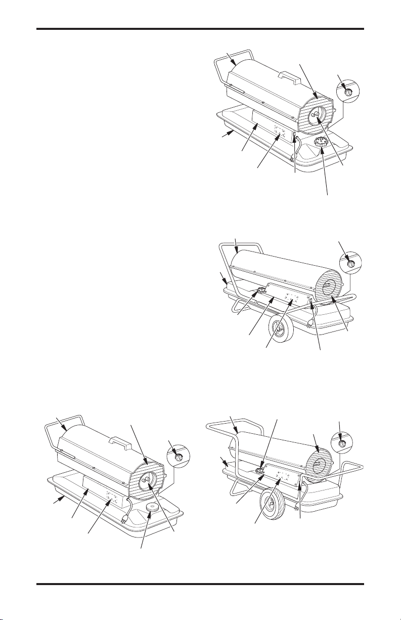
PRODUCT
IDENTIFICATION
Hot Air
Outlet
Fan Guard
Thermostat
Knob
Hot Air
Outlet
Fuel
Tank
Side Cover
Ignition Control
Assembly (On
Inside of Side
Cover)
Hot Air Outlet
Fuel
Tank
Fuel Cap/
Gauge
Side Cover
Ignition Control
Assembly (On Inside
of Side Cover)
Hot Air Outlet
Fuel
Tank
ON/OFF Switch
with Light
Figure 2 - 55/70 Model
Figure 3 - 115 Model
Fuel Cap/
Gauge
Fan Guard
Fuel Cap/Gauge
Thermostat Knob
ON/OFF Switch
with Light
Thermostat Knob
Fan Guard
Thermostat
Knob
Air Filter
End
Cover
Fan
Guard
Fuel
Tank
Side Cover
Ignition Control
Assembly (On Inside
of Side Cover)
Figure 1 - 40 Model
116170-01A 3
Fuel Cap
Air Filter
End
Cover
www.desatech.com
Side Cover
Ignition Control
Assembly (On Inside
of Side Cover)
Figure 4 - 165 Model
ON/OFF Switch
with Light
FUELS
VENTILATION
WARNING: Use only kerosene, #1/#2 diesel/fuel oil, JET A
or JP-8 fuels to avoid risk of fire or
explosion. Never use gasoline, oil
drained from crankcases, naphtha, paint thinners, alcohol or
other highly flammable fuels.
Use only kerosene, #1/#2 diesel/fuel oil, JET A or
JP-8 fuels. Heavier fuels such as No. 2 fuel oil or No.
2 diesel fuel may also be used but will result in:
• noticeable odor
• additional fuel filter maintenance
• the need for nontoxic, anti-icer additives in very
cold weather
Do not use fuels heavier than No. 2 grade or
heavy oils such as oil drained from crankcases.
These heavy oils will not ignite properly and will
contaminate the heater.
IMPORTANT: Use a KEROSENE ONLY (blue) or
DIESEL ONLY (yellow) storage container. Be sure
storage container is clean. Foreign matter such as rust,
dirt or water will cause the ignition control assembly
to shut down heater. Foreign matter may also require
heaterʼs fuel system to be frequently cleaned.
WARNING: Provide a fresh air
opening of at least three square
feet (2,800 square cm) for each
100,000 Btu/hr rating. Provide
extra fresh air if more heaters
are being used. The minimum
ventilation requirements must
be followed to avoid risks associated with carbon monoxide
poisoning. Make certain these
requirements are met prior to
operating heater.
Example: A 200,000 Btu/Hr (58.6 kw) heater
requires one of the following:
• a two-car garage door [16 feet (4.88 meter)
opening] raised 5 inches (12.7 cm)
• a single-car garage door [9 feet (2.74 meter)
opening] raised 8 inches (20.3 cm)
• two, 30 inch (76.2 cm) windows raised 15 inches
(38.1 cm)
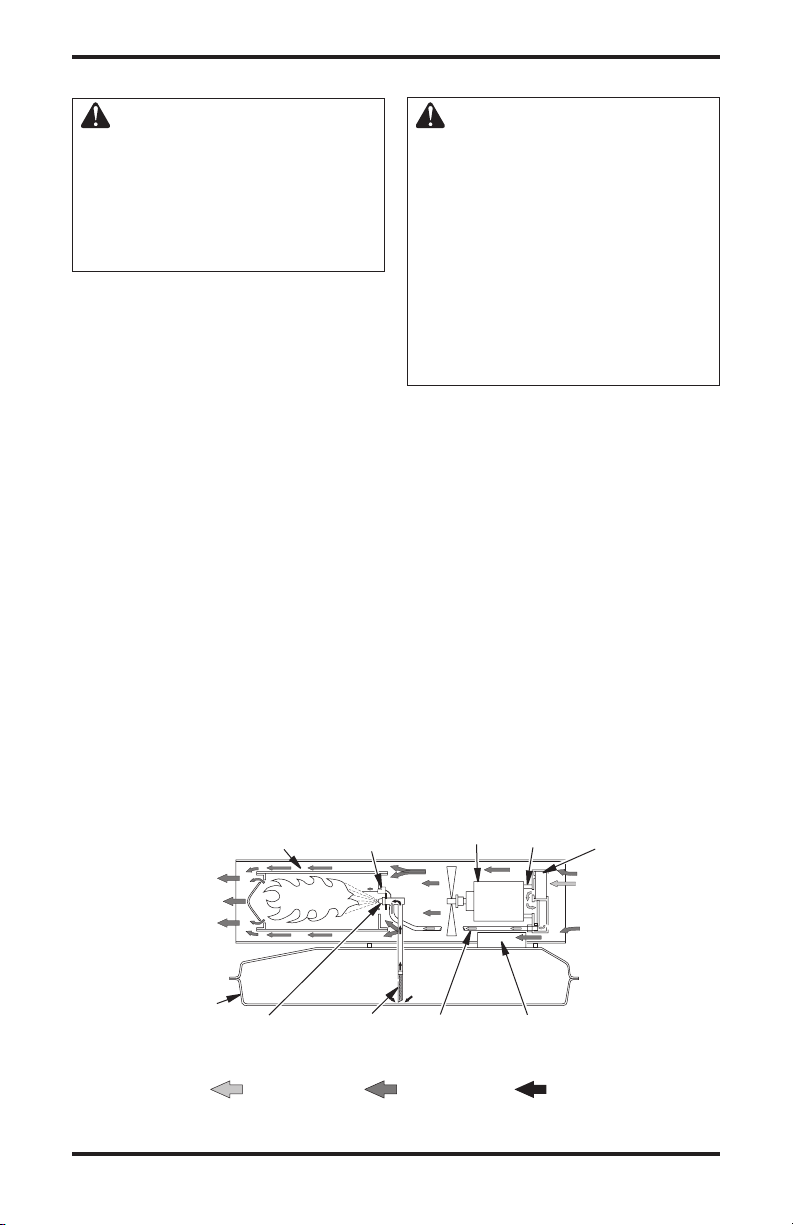
THEORY OF OPERATION
The Fuel System: The air pump forces air through the air line. The air is then pushed through the
nozzle. This air causes fuel to be lifted from the tank. A fine mist of fuel is sprayed into the combustion chamber.
The Air System: The motor turns the fan. The fan pushes air into and around the combustion chamber.
This air is heated and provides a stream of clean, hot air.
The Ignition System: The ignition control assembly provides power to the ignitor. This ignites the
fuel/air mixture in the combustion chamber.
The Flame-Out Control System: This system causes the heater to shut down if the flame goes out.
Fan
Motor
Combustion Chamber
Ignitor
Air Pump
Air Intake Filter
Clean
Heated
Air Out
Fuel
Tank
Nozzle
Air For Fuel
System
Figure 5 - Cross Section Operational View
4 116170-01A
Fuel
Filter
www.desatech.com
Air Line
To Burner
Air For
Combustion
And Heating
Ignition Control
Assembly
Cool Air In
Air Output Filter
Fuel
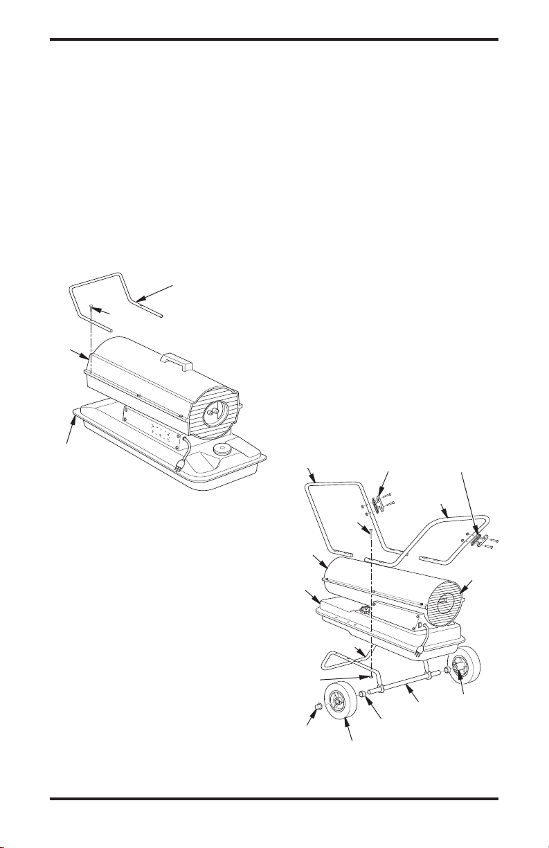
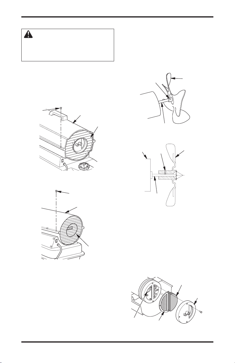
ASSEMBLY
(FOR 40, 55 AND 70 MODELS ONLY)
These models are furnished with a nose cone
guard. Nose cone guard and mounting screws are
found in the shipping carton.
Tools Needed
• 5/16" nut driver or wrench
1. Place nose cone guard on top of upper shell
flange. Make sure nose cone guard is on hot
air outlet end of heater.
2. Insert screws through nose cone guard and
upper shell flange.
3. Tighten screws firmly.
Nose Cone
Guard
Screw
Hot Air
Outlet
Upper Shell
Flange
Figure 6 - Nose Cone Guard Assembly,
40/55/70 Models Only
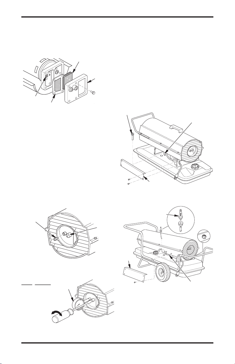
(FOR 115 AND 165 MODELS ONLY)
These models are furnished with wheels and a
handle. Some models are furnished with a second
handle also. Wheels, handle(s), and the mounting
hardware are found in the shipping carton.
Tools Needed
• Medium Phillips Screwdriver
• 3/8" Open or Adjustable Wrench
• Hammer
Slide axle through wheel support frame. Install
1.
wheel spacers if provided. Install wheels on axle.
IMPORTANT: When installing wheels, point
extended hub of wheels toward wheel support
frame (see Figure 7).
2. Place cap nuts on axle ends. Gently tap with
hammer to secure.
3. Place heater on wheel support frame. Line up
holes on fuel tank flange with holes on wheel
support frame. Be sure wheels are mounted
under the air inlet of heater.
4. Place handle(s) on top of fuel tank flange. In
sert screws through handle(s), fuel tank flange,
and wheel support frame. Attach nut finger
tight after each screw is inserted. If only one
handle is provided, be sure to mount handle
over outlet end of heater.
5. After all screws are inserted, tighten nuts
firmly.
Handle
Screw
Hot Air
Outlet
Fuel
Tank
Flange
Cord Cleat with Bolts
and Nuts (If provided)
Handle (If
provided)
Air
Inlet
-
Wheel Support
Frame
Nut
Extended
Axle
Cap Nut
Figure 7 - Wheel and Handle Assembly,
116170-01A 5
www.desatech.com
Wheel Spacer
(If Provided)
Wheel
115/165 Models Only
Hub
OPERATION
IMPORTANT: Review and understand the warnings in the Safety
Information section, page 2.
They are needed to safely operate this heater. Follow all local
ordinances and codes when
using this heater.
TO START HEATER
1. Follow all ventilation and safety information.
2. Locate heater to provide maximum circulation
of the heated air. Follow all location require
ments noted in Safety Information, page 2.
3. Fill fuel tank with kerosene, #1#2 diesel/fuel
oil, JET A or JP-8 fuel.
4. Attach fuel cap.
5. For thermostat models, turn thermostat knob
clockwise to the high position.
6. Plug heaterʼs power cord into approved,
grounded, three-wire extension cord. Extension
cord must be at least six feet (1.8 meters) long.
Extension Cord Size Requirement
6 to 10 feet (1.8 to 3 meters) long, use 18 AWG
(0.75 mm2) rated cord
11 to 100 feet (3.3 to 30.5 meters) long, use
16 AWG (1.0 mm2) rated cord
101 to 200 feet (30.8 to 61 meters) long, use
14 AWG (1.5 mm2) rated cord
7. Plug extension cord into standard 120 volt/60
hertz, 3-prong grounded outlet. Note: For
heater without ON/OFF switch, ignitor will
preheat for five seconds, then heater will
start.
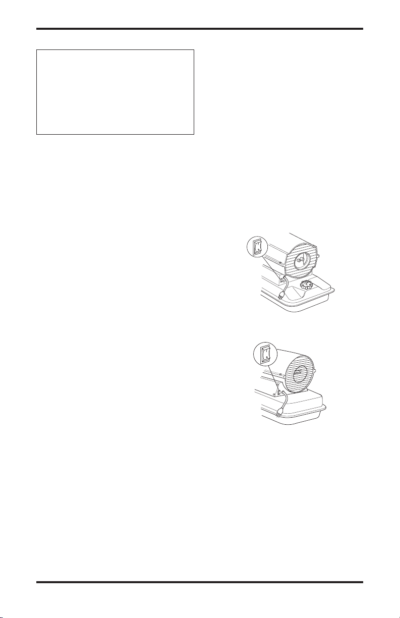
Note: For heater with ON/OFF switch, push
switch to ON(|) position and heater should
start in 5 seconds. If heater does not start, see
Troubleshooting, page 9.
8. For thermostat models, adjust thermostat knob
to the desired setting. Note: A cold heater may
affect the thermostat setting. This thermostat is
a general-heating control. It is not intended for
precise temperature control. Adjust thermostat
until heater cycles at the desired setting.
TO STOP HEATER
Without ON/OFF Switch
Unplug extension cord from outlet.
With ON/OFF Switch
Push ON/OFF switch to OFF (O) position. Unplug
heater when not in use.
TO RESTART HEATER
Without ON/OFF Switch
1. Unplug extension cord from outlet and wait
10 seconds. (Wait two minutes if heater has
been running.)
2. Repeat steps under To Start Heater
-
With ON/OFF Switch
1. Push ON/OFF switch to OFF (O) position and
wait 10 seconds (2 minutes if heater has been
running).
2. Repeat steps under
ON/OFF
Switch with
Light
Figure 8 - ON/OFF Switch, 55/70 Models
ON/OFF
Switch with
Light
Figure 9 - ON/OFF Switch, 115/165
To Start Heater.
Models
.
6 116170-01A
www.desatech.com
FUEL
F
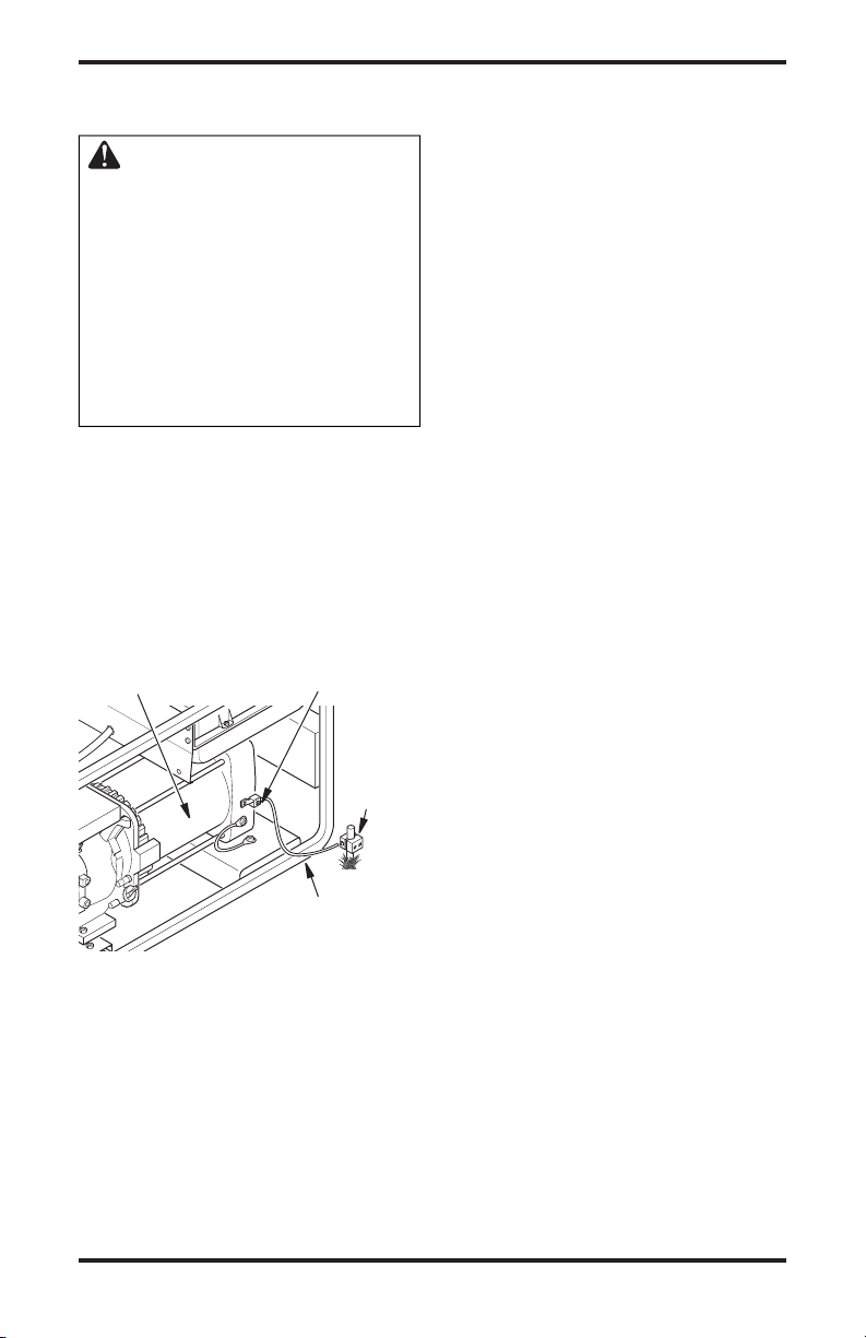
OPERATION WITH
PORTABLE GENERATOR
WARNING: Before operating
heater or any appliance from a
portable generator, verify that
generator has been properly connected to earth ground. Improper
grounding or failure to ground
generator can result in electrocution if a ground fault occurs.
Refer to owner’s manual supplied
by generator manufacturer for
proper grounding procedures.
The operating voltage range of the heater is 108 to
132 Volts (120 Volts +/- 10%). Prior to plugging
heater into generator the output voltage should
be verified (if generator is equipped with the automatic idle feature, the output voltage should be
measured with the generator running at full speed).
If the voltage does not measure in this range the
heater should not be plugged into the generator.
Operation, page 6, for starting, stopping,
Refer to
and resetting heater procedures.
STORING,
TRANSPORTING OR
SHIPPING
Note: If shipping, transport companies require
fuel tanks to be empty.
1. Drain fuel tank. Note: Some models have
drain plug on underside of fuel tank. If so, re
move drain plug to drain all fuel. If heater does
not have drain plug, drain fuel through fuel cap
opening. Be sure all fuel is removed.
2. Replace drain plug if provided.
3. If any debris is noted in old fuel, add 1 or 2
quarts of clean kerosene to tank, stir, and drain
again. This will prevent excess debris from
clogging filters during future use.
4. Replace fuel cap or drain plug. Properly dis
pose of old and dirty fuel. Check with local
automotive service stations that recycle oil.
5. If storing, store heater in dry place. Make sure
storage place is free of dust and corrosive
fumes.
IMPORTANT:
months for use during next heating season. Using
old fuel could damage heater.
Do not store kerosene over summer
-
-
Alternator
Figure 10 - Typical Generator Grounding
Method (Generator construction may
vary from that shown)
116170-01A 7
Ground Lug
Copper
or Brass
Grounding
Point
Ground Wire (#10
AWG - StrandedCopper)
www.desatech.com
PREVENTATIVE MAINTENANCE SCHEDULE
WARNING: Never service heater while it is plugged in, operating
or hot. Severe burns and electrical shock can occur.
Item
Fuel tank
Air output and lint filters
Air intake filter
Fuel filter
Ignitor
Fan blades
Motor
How Often
Flush every 150-200 hours of operation
or as needed
Replace every 500 hours of operation
or once a year
Wash and dry with soap and water every
500 hours of operation or as needed
Clean twice a heating season or as
needed
No maintenance required
Clean every season or as needed
Not required/permanently lubricated
How To
See Storing, Transporting, or
Shipping, page 7
See Air Output, Air Intake, and
Lint Filters, page 10
See Air Output, Air Intake, and
Lint Filters, page 10
See Fuel Filter, page 11
See Fan, page 10
TROUBLESHOOTING
WARNING: Never service heater while it is plugged in, operating
or hot. Severe burns and electrical shock can occur.
FAULT CONDITION
Motor does not start five seconds
after heater is plugged in
POSSIBLE CAUSE
1. No power to heater
2. ON/OFF switch not in the
ON(|) position
3. Thermostat setting is too low
REMEDY
1. Check circuit breaker in electrical panel
2. Verify the ON/OFF switch is in
ON (|) position and light is on
3. Turn thermostat knob to a
higher setting
WARNING: High voltage!
4.
Bad electrical connection between motor and ignition con
trol assembly or ignition control
assembly and power cord
5. Binding pump rotor
6. Defective ignition control as
sembly
7. Defective motor
8. Blown fuse or ignitor control
assembly
8 116170-01A
www.desatech.com
4. Check all electrical connec
-
tions. See Wiring Diagrams,
page 25
5. If fan does not turn freely, see
Pump Rotor,
-
6 Replace ignition control as
sembly
7. Replace motor
8. See Ignition Control Assembly,
page 15
page 14
-
-
FAULT CONDITION
Motor starts and runs but heater
does not ignite
TROUBLESHOOTING
Continued
POSSIBLE CAUSE
1. No fuel in tank
2. Pump pressure incorrect
3. Dirty fuel filter
4. Obstruction in nozzle
5. Water in fuel tank
WARNING: High voltage!
REMEDY
1. Fill tank with kerosene
2. See Pump Pressure Adjust
ment, page 11
3. See Fuel Filter, page 11
4.
See Nozzle Assembly, page 13
5. Drain and flush fuel tank with
clean kerosene. See Storing,
Tran sporting or Shipping,
page 7
-
Heater ignites but ignition con
trol assembly shuts heater off
after a short period of time
6. Bad electrical connection
between ignitor and ignition
control assembly
7. Defective ignitor
8. Defective ignition control
assembly
1. Pump pressure incorrect
-
2. Dirty air intake, air output,
and/or lint filter
3. Dirty fuel filter
4. Obstruction in nozzle
5. Photocell assembly not properly
installed (not seeing the flame)
6. Dirty photocell lens
WARNING: High voltage!
7. Bad electrical connection
between photocell and ignition
control assembly
8. Defective photocell
9. Defective ignition control as
sembly
6.
Check electrical connections.
See Wiring Diagrams, page 25
7. Replace ignitor, see page 12
8. Replace ignition control as
sembly
1. See Pump Pressure Adjust
ment, page 11
2. See Air Output, Air Intake, and
Lint Filters, page 10
3. See Fuel Filter, page 11
4.
See Nozzle Assembly, page 13
5. Make sure photocell boot is
properly seated in bracket
6. Clean photocell lens
7.
Check electrical connections.
See Wiring Diagrams, page 25
8. Replace photocell
9. Replace ignition control as
sembly
-
-
-
116170-01A 9
www.desatech.com
SERVICE PROCEDURES
WARNING: To avoid risk of
burn and electrical shock, never
attempt to service heater while it
is plugged in, operating or hot.
UPPER SHELL REMOVAL
1. Remove screws along each side of heater using
5/16" nut-driver. These screws attach upper and
lower shells together. See Figure 11 or 12.
2. Lift upper shell off.
3. Remove fan guard.
4. Clean fan using a soft cloth moistened with
kerosene or solvent.
5. Dry fan thoroughly.
6. Replace fan on motor shaft. Place fan hub flush
with end of motor shaft (see Figure 14).
7. Place setscrew on flat of shaft. Tighten setscrew
firmly (40-50 inch-pounds/4.5-5.6 n-m).
8. Replace fan guard and upper shell.
Setscrew
Fan
Screw
Figure 11 - Upper Shell Removal,
40/55/70 Models Only
Upper Shell
Screw
Upper Shell
Fan Guard
Motor Shaft
Figure 13 - Fan, Motor Shaft, and
Setscrew Location
Motor
Setscrew
Motor
Shaft
Figure 14 - Fan Cross Section
Fan
Flush
AIR OUTPUT, AIR INTAKE AND LINT
FILTERS
1. Remove upper shell (see Figure 11 or 12).
2.
Remove filter end cover screws using 5/16" nut-
Fan Guard
Figure 12 - Upper Shell Removal,
115/165 Models Only
FAN
IMPORTANT: Remove fan from motor shaft
before removing motor from heater. The weight
of the motor resting on the fan could damage the
fan pitch (see Figure 13).
1. Remove upper shell (see Figure 11 or 12).
2. Use 1/8" allen wrench to loosen setscrew
which holds fan to motor shaft.
3. Slip fan off motor shaft.
10 116170-01A
www.desatech.com
driver (see Figure 15 or Figure 16, page 11).
3. Remove filter end cover.
4. Replace air output and lint filters.
5. Wash or replace air intake filter (see Preventa
tive Maintenance Schedule, page 8).
Air Intake Filter
Filter End
Cover
Lint Filter
Figure 15 - Air Output, Air Intake, and
Air Output Filter
Lint Filters, 40/55/70 Models Only
-
SERVICE PROCEDURES
Continued
6. Replace filter end cover.
7. Replace fan guard and upper shell.
IMPORTANT: Do not oil filters.
Air Intake Filter
Filter
End
Cover
Lint Filter
Air Output Filter
Figure 16 - Air Output, Air Intake, and
Lint Filters, 115/165 Models Only
PUMP PRESSURE ADJUSTMENT
1. Remove pressure gauge plug from filter end
cover (see Figure 17).
2. Install accessory pressure gauge (part number
HA1180).
3. Start heater (see
motor to reach full speed.
4. Adjust pressure. Turn relief valve to right to
increase pressure. Turn relief valve to left to
decrease pressure. See specifications correct
pressure for each model (see Figure 18).
5. Remove pressure gauge. Replace pressure
gauge plug in filter end cover.
Pressure
Gauge
Plug
Operation, page 6). Allow
Relief
Valve
FUEL FILTER
1. Remove side cover screws using 5/16" nutdriver.
2. Remove side cover.
3. Pull upper fuel line off fuel filter neck (see
Figure 19 or 20).
4. Carefully pry bushing, fuel filter, and lower
fuel line (115/165 Models only) out of fuel
tank (see Figure 20).
5. Wash fuel filter with clean fuel and replace in
tank.
6. Attach upper fuel line to fuel filter neck.
7. Replace side cover.
Fuel Filter and
Bushing
Upper Fuel Line
Side Cover
Figure 19 - Fuel Filter Removal,
40/55/70 Models
Fuel Filter, Bushing,
and Lower Fuel Line
Side
Figure 17 - Pressure Gauge Plug
Removal (70 Model Shown)
Pump
Model Pressure
40 3.0 PSI
55 3.4 PSI
70 4.7 PSI
115 5.1 PSI
165 5.6 PSI
Figure 18 - Adjusting Pump Pressure
116170-01A 11
Pressure
Gauge
(70 Model Shown)
www.desatech.com
Cover
Upper Fuel Line
Figure 20 - Fuel Filter Removal,
115/165 Models
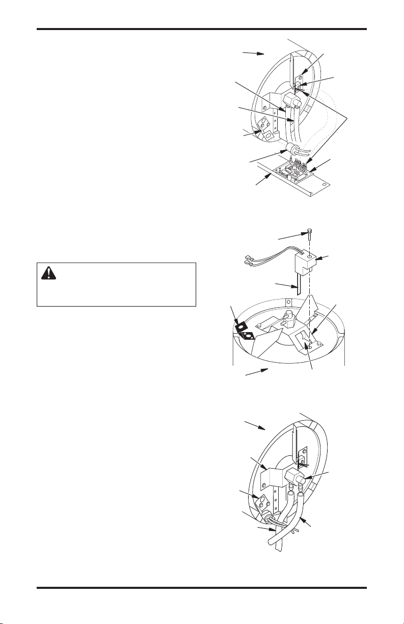
SERVICE PROCEDURES
Continued
IGNITOR
1. Remove upper shell and fan guard (See Upper
Shell Removal, page 10).
2. Remove fan (see page 10).
3. Remove 4 side cover screws with a 5/16" nut
driver. Remove side cover (see Figures 19 or
20, page 11).
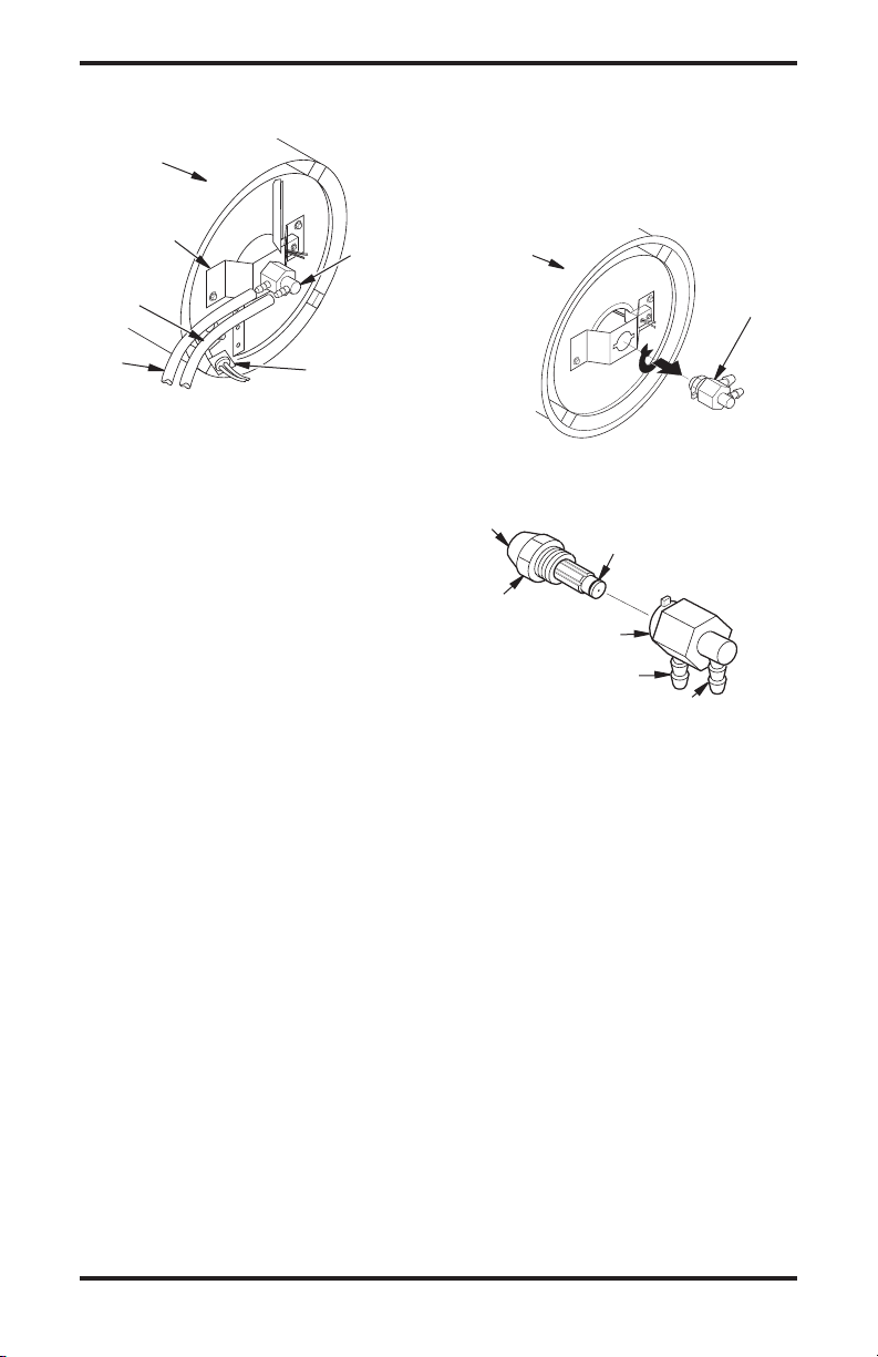
4. Disconnect ignitor wires from ignition control
assembly (see Figure 21). Pull the ignitor
wires up through the hole in the lower shell.
5. Disconnect fuel line hose and air line hose.
Remove photocell from photocell bracket (see
Figure 21).
6. Remove combustion chamber. Stand com
bustion chamber on end with nozzle adapter
bracket on top (see Figure 22).
7. Remove ignitor screw with a 1/4" nut driver.
Carefully remove ignitor from nozzle adapter
bracket.
Combustion
Chamber
Air Line
Hose
Fuel
Line
Hose
Photocell
Bracket
Photocell
Assembly
Side Cover
-
Figure 21 - Disconnecting Ignitor Wires
from Ignition Control Assembly
Ignitor Screw/
Washer Assembly
Nozzle
Adapter
Bracket
Ignitor
Ignitor
Wire
Ignition
Control
Assembly
Ignitor
CAUTION: Do not bend or
strike ignitor element. Handle
with care.
8. Carefully remove replacement ignitor from
packing.
9. Carefully guide ignitor into opening in nozzle
adapter bracket. Do not strike ignitor element.
Attach ignitor to nozzle adapter bracket with
screw using a 1/4" nut driver (see Figure 23).
Torque .90 to 1.69 N-m (8 to 15 in-lbs) Do not
over torque.
10. Replace combustion chamber.
11. Route the ignitor wires back down through the
hole in the lower shell. Connect wires to the
ignition control assembly (see Figure 22).
12. Replace side cover (see Figures 19 or 20,
page 11).
13. Connect and route fuel line hose and air line
hose to nozzle adapter assembly. See Fuel and
Air Line Replacement and Proper Routing
page 14.
14. Replace photocell in photocell bracket. Route
wires as shown in either (see Figure 23 or
Figure 24, page 13).
15. Replace fan (see page 10).
16.
Replace fan guard and upper shell (see
page 10).
Ignitor
Photocell
Bracket
Combustion
Chamber
Combustion
Chamber
Photocell
,
Bracket
Element
Nozzle Adapter
Bracket Opening
Figure 22 - Ignitor Replacement
Nozzle
Adapter
Bracket
Air Line
Hose
Figure 23 - Removing Air and Fuel Line
Hoses (40/55/70 Models Only)
Fuel Line Hose
Nozzle
Adapter
Bracket
Nozzle/
Adapter
Assembly
12 116170-01A
www.desatech.com
SERVICE PROCEDURES
Continued
Combustion
Chamber
Nozzle
Adapter
Bracket
Air Line
Hose
Fuel
Line
Hose
Figure 24 - Removing Air and Fuel Line
Hoses (115/165 Models Only)
NOZZLE ASSEMBLY
1. Remove upper shell (see Upper Shell Removal, page 10).
2. Remove fan (see
3.
Remove fuel and air line hoses from nozzle assembly (see Figure 23, page 12 or Figure 24).
4. Turn nozzle assembly 1/4 turn to left and pull
toward motor to remove (see Figure 25).
5. Place plastic hex-body into vise and lightly
tighten.
6. Carefully remove nozzle from the nozzle adapter
using 5/8" socket wrench (see Figure 26).
7. Blow compressed air through face of nozzle.
This will free any dirt in nozzle area.
8. Inspect nozzle sleeve for damage.
9. Replace nozzle into nozzle adapter until
nozzle seats. Tighten 1/3 turn more using 5/8"
socket wrench 4.5 to 5.1 N-m (40 to 45 in-lbs).
See Figure 26.
10. Attach nozzle assembly to burner strap (see
Figure 25).
Fan, page 10).
Nozzle/
Adapter
Assembly
Photocell
Bracket
11. Attach fuel and airline hoses to nozzle assembly. See Fuel and Air Line Replacement
and Proper Routing, page 14.
12. Replace fan (see
13. Replace fan guard and upper shell (see Upper
Shell Removal, page 10).
Combustion
Chamber
Figure 25 - Removing Nozzle/Adapter
Nozzle Face
Nozzle
Nozzle Adapter
Figure 26 - Nozzle and Nozzle Adapter
Fan, page 10).
Assembly
Nozzle Sleeve
Air Line
Fitting
Fuel Line Fitting
Nozzle/
Adapter
Assembly
116170-01A 13
www.desatech.com

SERVICE PROCEDURES
Continued
FUEL AND AIR LINE REPLACEMENT
AND PROPER ROUTING
1. Remove upper shell (see Upper Shell Removal, page 10).
2. Remove side cover screws using 5/16" nut
driver (see Figure 19 or 20, page 11).
3. Remove side cover.
4. Inspect fuel and air line hoses for cracks and/or
holes. If fuel line hose is damaged, disconnect
from nozzle adapter (see Figure 23 or 24) and
from fuel filter (see Fuel Filter, page 11). If air
line hose is damaged, disconnect from nozzle
adapter (see Figure 23, page 12 or Figure 24,
page 13) and from barb fitting on pump end
cover (see Figure 27).
5. Install new air and/or fuel line. Attach one
end of air line hose to barb fitting on pump
end cover (see Figure 27) and the other end
to nozzle adapter (see Figure 23, page 12 or
Figure 24, page 13). Attach one end of fuel
line hose to fuel filter (see Fuel Filter, page
11) and the other end to nozzle adapter (see
Figure 23, page 12 or Figure 24, page 13).
Note: Route hoses as shown in Figure 23, page
12 or Figure 24, page 13, according to model.
Hoses are not to touch photocell bracket.
6. Replace side cover.
7. Replace upper shell and fan guard (see
Shell Removal, page 10).
Upper
PUMP ROTOR
(Procedure if Rotor is Binding)
1. Remove upper shell (see Upper Shell Re
moval, page 10).
2. Remove filter end cover screws using 5/16"
nut driver (see Figure 28 or 29).
3. Remove filter end cover and air filters.
4. Remove pump plate screws using 5/16"
nut-driver.
5. Remove pump plate.
6. Remove rotor, insert, and blades (see Figure
28 or 29).
7. Check for debris in pump. If debris is found,
blow out with compressed air.
8. Install insert and rotor.
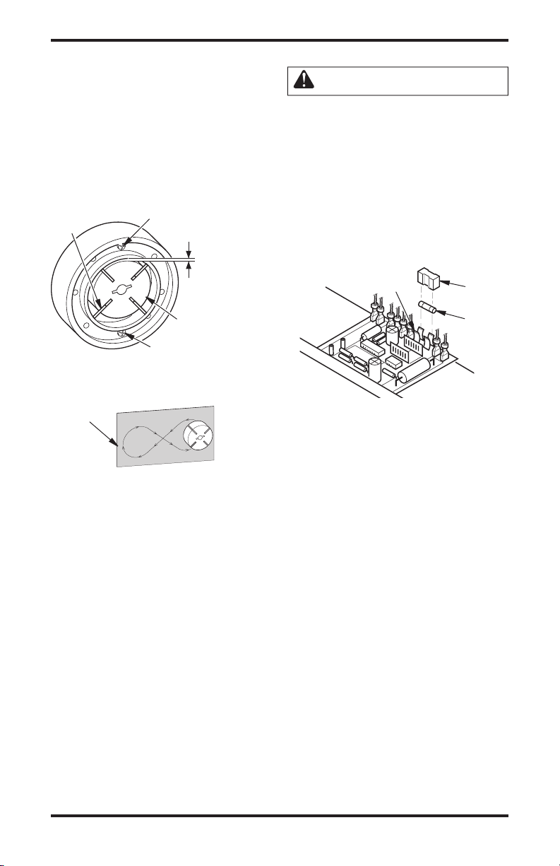
9.
Check gap on rotor. Adjust to .076/.101 mm
(.003"/.004") if needed (see Figure 30, page 15).
Note: Rotate rotor one full turn to ensure the
gap is .076/.101 mm (.003"/.004") at tightest
position. Adjust if needed.
10. Install blades, pump plate, air filters, and filter
end cover.
11. Replace fan guard and upper shell (see
Shell Removal, page 10).
12. Adjust pump pressure (see Pump Pressure
Adjustment, page 11).
Blade
Pump
Plate
Upper
Air Intake
Filter
Filter
End
Cover
-
Pump End Cover
Barb
Fitting
Air Hose
Figure 27 - Air Hose to Barb Fitting
14 116170-01A
115/165 Models40/55/70 Models
Barb Fitting
Insert
www.desatech.com
Insert
Rotor
Air Output Filter
Figure 28 - Rotor Location, 40/55/70
Rotor
Air Output Filter
Figure 29 - Rotor Location, 115/165
Models
Blade
Pump Plate
Air
Intake
Filter
Filter End Cover
Models
SERVICE PROCEDURES
Continued
Note: If rotor is still binding, proceed as
follows.
13. Perform steps 1 through 6.
14. Place fine grade sandpaper (600 grit) on flat
surface. Sand rotor lightly in “figure 8” motion
four times (see Figure 31).
15. Reinstall insert and rotor.
16. Perform steps 10 through 12.
Blade
Gap Adjusting Screw
.003"/.004"
(.076-.101 mm)
Gap Measured
With Feeler
Gauge
IGNITION CONTROL ASSEMBLY
WARNING: High voltage!
1. Unplug heater.
2. Remove side cover screws (4) using 5/16" nutdriver to expose ignition control assembly.
3. Remove fuse cover (see Figure 32).
Remove fuse from fuse clips (see Figure 32).
4.
5. Replace fuse with fuse of the same type and
rating (GMA-10). Do not substitute a fuse
with a higher current rating.
6. Replace fuse cover (see Figure 32).
7. Replace side cover (see Figures 19 or 20,
page 11).
Fuse Clips
Fuse
Cover
Rotor
Gap Adjusting Screw
Figure 30 - Gap Adjusting Screw
Locations
Sandpaper
Figure 31 - Sanding Rotor
Figure 32 - Replacing Fuse
Fuse
SPECIFICATIONS
Model Size 40 55 70 115 165
Output Rating (Btu/Hr) 40,000 55,000 70,000 115,000 165,000
Fuel Use only kerosene, #1/#2 diesel/fuel oil, JET A or JP-8 fuels*
Fuel Tank Capacity
(U.S. Gal./Liters) 3/11.3 5/18.9 5/18.9 9/34 13.5/51
Fuel Consumption
(Gal. Per Hr/Liters Per Hr) .3/1.14 .44/1.67 .52/1.97 .85/3.00 1.2/4.54
Pump Pressure (psi) 3.0 3.4 4.7 5.1 5.6
Electric Requirements 120 V/60 HZ (Same All Models)
Amperage (Normal Run) 2.0 2.0 2.8 3.6 3.6
Motor RPM 1725 1725 3440 3440 3440
Hot Air Output (CFM) 170 180 360 490 575
Shipping Weight 32/14.5 35/15.9 35/15.9 54/24.5 65/29.5
(Approximate lbs./kg)
Heater Weight without Fuel 28/12.2 30/14 30/14 46/21 55/25
(Approximate lbs./kg)
* Use of #2 diesel & fuel oil will result in noticeable odor and could require additional fuel filter main
tenance. Use in extreme cold temperatures may require nontoxic anti-icer additives.
-
116170-01A 15
www.desatech.com
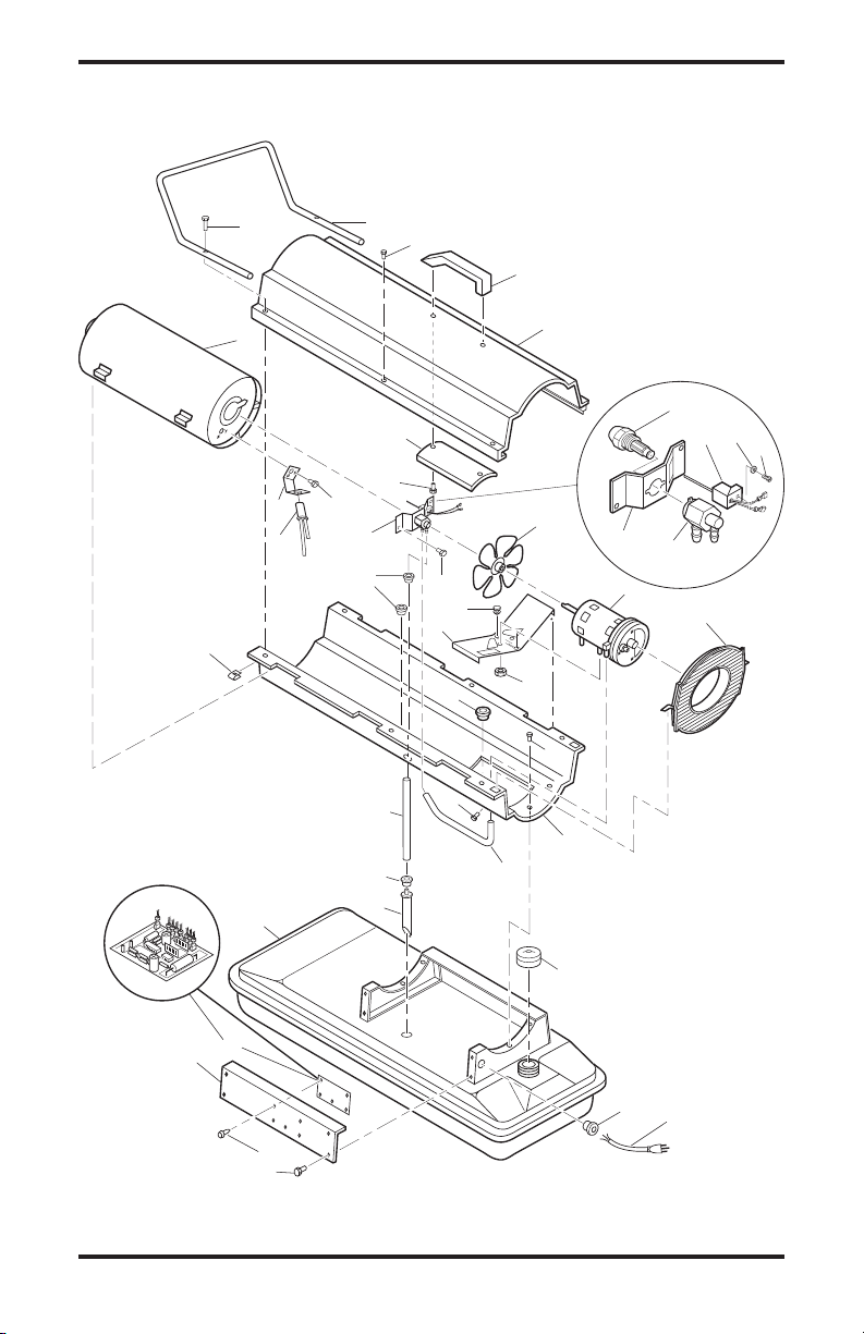
ILLUSTRATED PARTS BREAKDOWN
1
2
3
4
31
5
6
7
8
9
10
11
12
13
14
15
16
9-2
9-1
9-3
9-4
9-5
17
18
19
20
21
22
23
24
25
26
27
28
29
30
34
35
36
32
33
9-6
37
MODELS BC40 AND RC40
16 116170-01A
www.desatech.com
PARTS LIST
MODELS BC40 AND RC40
This list contains replaceable parts used in your heater. When ordering parts, be sure to provide the correct
model and serial numbers (from the model plate), then the part number and description of the desired part.
KEY PART
NO. NUMBER DESCRIPTION QTY.
1 M51104-01 Handle 1
2 098511-67 Upper Shell (Service Part Will Be Black) 1
3 M11084-29 Screw, #10-16 x 3/4" 2
4 108631-01 Screw, #10-16 x 1" 2
5 098512-58 Combustion Chamber 1
6 M10908-2 Screw, #6-32 x 3/8" 2
7 103154-03 Photocell Bracket 1
8 M16656-24 Photocell Assembly 1
9
(see page 22)
10 M11084-26 Screw, #10-16 x 3/8" 2
11 103684-01 Fan 1
12
(see page 22)
13 M51105-01 Fan Guard 1
14 098219-38 Power Cord 1
15 M11143-1 Strain Relief Bushing 1
16 NTC-4C Hex Lock Nut, 1/4-20 2
17 M11084-26 Screw, #10-16 x 3/8" 4
18 M50631 Rubber Bumper 2
19 097461-09 Side Cover 1
20 101205-01 Motor Bracket 1
21 M30865-02 Bushing 2
22 M11271-8 Clip Nut 6
23 M50104-02 Bushing 1
24 M11084-26 Screw, #10-16 x 3/8" 6
25 M10908-14 Screw, #8-32 x 3/8" 1
26 098511-234 Lower Shell (Service Part will be Black) 1
27 M50814-06 Rubber Airline 1
28 079973-01 Fuel Line 1
29 M50876-04 Fuel Filter with bushing 1
30 M10990-3 Rubber Bushing 1
31 079532-01 Guard, Nose Cone 1
32 102349-01 PCB Support 5
33 104068-02 Ignition Control Assembly 1
34 097702-01 Fuel Cap (Includes Gasket) 1
35 108088-01 Fuel Tank 1
36 M51108-01 Shell Heat-Shield 1
37 M15823-27 Screw, #10-16 x 1/2" 4
103814-01 Wire Tie 1
105550-01 Warning/Maintenance Decal 1
105550-02 Warning/Maintenance Decal 1
Burner Head Assembly 1
Motor 1
PARTS AVAILABLE - NOT SHOWN
116170-01A 17
www.desatech.com

1
2
3
4
5
6
7
8
9
10
11
12
13
14
15
16
17
18
19
20
21
22
23
24
25
26
27
28
29
30
33
34
35
40
31
32
42
41
38
37
39
36
9-1
9-3
9-4
9-5
ILLUSTRATED PARTS BREAKDOWN
MODELS BC55CT, RC55CT, UKC55CT, BC70ET, RC70ET AND UKC70ET
18 116170-01A
www.desatech.com

PARTS LIST
MODELS BC55CT, RC55CT, UKC55CT, BC70ET, RC70ET AND UKC70ET
This list contains replaceable parts used in your heater. When ordering parts, be sure to provide the correct
model and serial numbers (from the model plate), then the part number and description of the desired part.
KEY PART
NO. NUMBER DESCRIPTION QTY.
1 M51104-01 Handle 1
2 098511-67 Upper Shell (Service Part Will Be Black) 1
3 M11084-29 Screw, #10-16 x 3/4" 2
4 108631-01 Screw, #10-16 x 1" 2
5 098512-50 Combustion Chamber (55) 1
098512-51 Combustion Chamber (70) 1
6 M10908-2 Screw, #6-32 x 3/8" 2
7 103154-03 Photocell Bracket 1
8 M16656-24 Photocell Assembly 1
9 (see page 22) Burner Head Assembly 1
10 M11084-26 Screw, #10-16 x 3/8" 2
11 103684-01 Fan (55) 1
M29678 Fan (70) 1
12 (see page 22) Motor and Pump Assembly 1
13 M51105-01 Fan Guard 1
14 113065-01 Power Cord 1
15 M11143-1 Strain Relief Bushing 1
16 NTC-4C Hex Lock Nut, 1/4-20 2
17 M11084-26 Screw, #10-16 x 3/8" 8
18 M50631 Rubber Bumper 2
19 097461-16 Side Cover 2
20 101205-01 Motor Bracket 1
21 M50104-06 Bushing 1
22 M11271-8 Clip Nut 6
23 M50104-02 Bushing 1
24 M11084-26 Screw, #10-16 x 3/8" 6
25 M10908-14 Screw, #8-32 x 3/8" 1
26 098511-234 Lower Shell (Service Part Will Be Black) 1
27 M50814-06 Rubber Airline 1
28 079973-01 Fuel Line 1
29 M50876-05 Fuel Filter with bushing 1
30 M10990-3 Rubber Bushing 1
31 102349-01 PCB Support 5
32 104068-02 Ignition Control Assembly 1
33 113280-01 Fuel Cap w/ Gauge (includes Gasket)
(Use with Fuel Tank 113279-01) 1
34 113279-01 Fuel Tank (Plastic Filler Neck) 1
35 M51108-01 Shell Heat-Shield 1
36 104458-01 Thermostat 1
37 M12461-18 Screw, #8-32 x 7/8" 1
38 104460-01 Thermostat Knob 1
39 WLE-2 Lock Washer, EXT #8 1
40 113461-01 ON/OFF Switch 1
41 M15823-27 Screw #10-16 x 1/2" 4
42 079532-01 Nose Cone Guard 1
103814-01 Wire Tie (For Ignition Control Assembly) 1
M9900-170 Wire Assembly
(Thermostat to Ignition Control Assembly) 1
079010-46 Wire Assembly (Connects Switch to Thermostat
or Ignition Control) 1
PARTS AVAILABLE - NOT SHOWN
116170-01A 19
www.desatech.com

ILLUSTRATED PARTS BREAKDOWN
1
2
3
23
19
9
10
16
11
12
15
25
27
24
28
29
20
22
21
30
31
17
14
14
33
34
35
36
32
26
40
18
5
4
6
7
8
7-2
7-1
7-5
7-4
7-3
37
13
39
38
7-6
Upper Tier Burner Head 125/170T
MODELS
BC115DT, RC115DT, UKC115DT, BC165DT, RC165DT AND UKC165DT
20 116170-01A
www.desatech.com

PARTS LIST
MODELS BC115DT, RC115DT, UKC115DT, BC165DT, RC165DT AND UKC165DT
This list contains replaceable parts used in your heater. When ordering parts, be sure to provide the correct
model and serial numbers (from the model plate), then the part number and description of the desired part.
KEY PART
NO. NUMBER DESCRIPTION QTY.
1 098511-292 Upper Shell (Service Part Will Be Black) 1
2 M15823-27 Screw, #10-16 x 1/2" 8
3 098512-71 Combustion Chamber (115) 1
098512-75 Combustion Chamber (165) 1
4 103154-05 Photocell Bracket (115) 1
M16660-02 Photocell Bracket (165) 1
5 M10908-2 Screw, #6-32 x 3/8" 2
6 M16656-24 Photocell Assembly 1
7 (See page 22) Burner Head Assembly 1
8 M11084-26 Screw, #10-16 x 3/8" 2
9 097293-01 Fan (115) 1
102042-01 Fan (165) 1
10 (See page 23) Motor and Pump Assembly 1
11 M50631 Rubber Bumper 2
12 101206-01 Motor Mounting Bracket 1
13 M12461-18 Screw, #8-32 x 7/8" 1
14 104068-02 Ignition Control Assembly 1
15 NTC-4C Hex Lock Nut, 1/4-20 2
16 111037-01 Fan Guard 1
17 M27417 Drain Plug (Includes “o” Ring) 1
18 107878-02 Button Plug 1
19 M51345-06 Fuel Line 1
20 106896-01 Fuel Filter 1
21 M51151-01 Fuel Line Tube (115) 1
M51151-02 Fuel Line Tube (165) 1
22 M10990-3 Rubber Bushing 1
23 M50814-03 Airline 1
24 098511-293 Lower Shell (Service Part Will Be Black) 1
25 M50104-06 Bushing 1
26 M50104-01 Bushing 1
27 M11084-26 Screw, #10-16 x 3/8" 6
28 M11271-8 Clip Nut 8
29 M10908-14 Screw, #8-32 x 3/8" 1
30 113279-02 Fuel Tank 115 1
113279-03 Fuel Tank 165 1
31 113280-02 Fuel Cap w/ Gauge (includes Gasket) 115 1
113280-03 Fuel Cap w/ Gauge (includes Gasket) 165 1
32 102349-01 P.C. Board Support 5
33 M11143-1 Strain Relief Bushing 1
34 113065-01 Power Cord 1
35 M51077-18 Side Cover 2
36 M11084-26 Screw, #10-16 x 3/8" 8
37 104460-01 Thermostat Knob 1
38 104458-01 Thermostat 1
39 WLE-2 Lock Washer, EXT #8 1
40 113461-01 ON/OFF Switch with Light 1
103814-01 Wire Tie (Not Shown - Groups wires connected to Ignition
Control Assembly) 1
M9900-77 Wire (Not Shown - Connects T-stat to Ignition Control Assembly) 1
079010-46 Wire (Not Shown - Connects ON/OFF Switch to Ignition
Control Assembly or Thermostat if Equipped) 1
116170-01A 21
www.desatech.com

ILLUSTRATED PARTS BREAKDOWN
2
1
5
4
3
6
BURNER HEAD ASSEMBLY
KEY PART
NO. NUMBER DESCRIPTION QTY.
1 HA3006 Nozzle Assembly (40) 1
HA3024 Nozzle Assembly (55) 1
HA3026 Nozzle Assembly (70) 1
HA3027 Nozzle Assembly (115) 1
HA3028 Nozzle Assembly (165) 1
2 HA1000 Ignitor Kit 1
3 M10908-75 Screw, #6-32 x 7/8" 1
4 102336-01 Nozzle Adapter Bracket 1
5 104056-01 Nozzle Adapter (40) 1
104054-01
6 103347-01 Washer 1
MOTOR AND PUMP ASSEMBLY MODELS
BC40, RC40, BC55CT, RC55CT, UKC55CT, BC70ET, RC70ET AND UKC70ET
1
2
3
4
Nozzle Adapter (55/70/115/165)
5
1
18
17
16
KEY PART
NO. NUMBER DESCRIPTION QTY.
1 102001-01 Motor (40/55) 1
102001-20 Motor (70) 1
2 079975-02 Pump Body (40/70) 1
079975-03 Pump Body (55) 1
3 M22009*, ** Insert 1
4 M22456-1* Rotor (40 & 70) 1
M22456-2** Rotor (55) 1
5 M29608 Pump End Cover 1
6 M29632*** Lint Filter 1
7 M29633*** Intake Filter 1
8 M29609 Filter End Cover 1
9 M12461-31 Screw, #10-32 x 1" 3
10 M27694 ∞ Adjusting Screw 1
11 M10993-1 ∞ Pressure Relief Spring 1
12 M22997 ∞ Plug 1
13 M8940 ∞ Steel Ball, 1/4" Diameter 1
14 M29612-01*** Output Filter 1
15 M12461-31 Screw, #10-32 x 1" (40/70) 6
M12461-32 Screw, #10-32 x 1
16 103676-01 Nylon Elbow, 90° 1
17 M8643* Blade (40/70) 4
M8643-2** Blade (55) 4
18 FHPF3-5C Screw (40/70) 2
FHPF3-6C Screw (55) 2
22 116170-01A
1
/8" (55) 6
www.desatech.com
* Included in Rotor Kit (Part
** Included in Rotor Kit (Part
*** Included in Filter Kit (Part
∞ Included in Pump
6
14
7
15
13
No. HA3004)
No. HA3005)
No. HA3014)
Adjustment Kit (Part No.
HA3020)
12
8
9
11
10

ILLUSTRATED PARTS BREAKDOWN
MODELS BC115DT, RC115DT, UKC115DT, BC165DT, RC165DT AND UKC165DT
1
2
3
4
5
13
6
12
17
16
15
13
14
KEY PART
NO. NUMBER DESCRIPTION QTY.
1 102001-30 Motor 1
2 079975-02 Pump Body 1
3 FHPF3-5C Screw, #10-32 x 5/8" 2
4 M22009** Rotor Insert 1
5 M22456-1** Pump Rotor 1
6 M50545 Pump End Cover 1
7 M12179** Intake Filter 1
8 M16545 Filter End Cover 1
9 M8940** Steel Ball, 1/4" Diameter 1
10 M10993-1** Relief Spring 1
11 M27694** Adjusting Screw 1
12 M22997** Plug 1
13 M12461-31 Screw, #10-32 x 1" 10
14 M12244-1** Output Filter 1
15 M11637** Lint Filter 1
16 M50820-02 Barb Fitting 1
17 M8643** Blade 4
** Included in Rotor Kit (Part No. HA3004)
7
8
9
10
11
116170-01A 23
www.desatech.com

ILLUSTRATED PARTS BREAKDOWN
WHEELS AND HANDLE PARTS LIST
1
2
10
3
10
4
6
7
5
9
8
KEY PART NUMBER
NO. 115 MODELS 165 MODELS DESCRIPTION QTY.
1 079998-02 099614-01 Handle, Front 1
2 M51334-02 099614-02 Handle, Rear (if provided) 1
3
3 M12345-33 M12345-33 Screw, #10-24 x 1
/4" 8
4 M12342-3 M12831-5 Wheel Support Frame 1
5 NTC-3BZ NTC-3BZ Hex Nut, #10-24 8
6 107426-01 — Wheel Kit (115)
(Contains 2 Black Wheels and Cap Nuts) 1
— 113326-01 Pneumatic Wheel Kit (165)
(Contains 2 Black Wheels, Cap Nuts, & Spacers) 1
7 M28526 M28526 Cap Nut 2
8 M51015-01 M16801-5 Axle 1
9 — 113497-01 Wheel Spacer (165 only) 2
10 113193-01 113193-01 Cord Cleat Kit (if provided)
(Contains 2 Cleats, 4 Nuts and 4 Bolts) 1
24 116170-01A
www.desatech.com

Power Plug
120V/60Hz
Blue
Blue
White
Photocell
Ignition Control Assembly
Green
Black
Black
Green
Red
Black
Yellow
Yellow
Motor
Ignitor
Thermostat
Photocell
Photocell
Ignitor
Motor Return
AC Neutral (L2)
120V (L1)
Ignitor
Motor
White
ON/OFF Switch
with Light
2
1
3
Power Plug
120V/60Hz
Blue
Blue
White
White
Photocell
Ignition Control Assembly
Green
Green
Red
Black
Black
Yellow
Yellow
Motor
Ignitor
Thermostat
Photocell
Photocell
Ignitor
Motor Return
AC Neutral (L2)
120V (L1)
Ignitor
Motor
WIRING DIAGRAMS
(40 Models)
(55/70/115/155/165 Models)
Figure 33 - Wiring Diagrams
116170-01A 25
www.desatech.com

ACCESSORIES
Heater accessories and parts are available at your
local dealer. Should your dealer not stock or is unable to order a particular accessory or part, please
contact DESA Industries for more information.
DESA Industries of Canada, Inc.
2220 Argentia Road, Unit #4
Mississauga, Ontario L5N 2K7
Parts Department
1-905-826-8010
AIR GAUGE KIT - HA1180
For all models. Special tool to check pump
pressure.
THERMOSTAT KIT - HA1210
For 40 model. Keeps your building at the temperature you select day and night. Helps economize
on fuel.
IGNITION CONTROL ASSEMBLY/
PHOTOCELL TESTER - HA1170
Special tool used to test the ignition control assembly and photocell.
HEAVY DUTY WHEELS AND
HANDLE KIT - HA1202
For heavy duty applications. Makes your heater
even more portable and convenient. Fits 40/55/70
models.
26 116170-01A
www.desatech.com

NOTES
_____________________________________________________
______________________________________________________
______________________________________________________
______________________________________________________
______________________________________________________
______________________________________________________
______________________________________________________
______________________________________________________
______________________________________________________
______________________________________________________
______________________________________________________
______________________________________________________
______________________________________________________
_____________________________________________________
______________________________________________________
______________________________________________________
______________________________________________________
______________________________________________________
______________________________________________________
______________________________________________________
______________________________________________________
______________________________________________________
116170-01A 27
www.desatech.com

WARRANTY AND REPAIR SERVICE
KEEP THIS WARRANTY
Model No.
Serial No.
Date of Purchase
LIMITED WARRANTIES FOR NEW AND FACTORY
RECONDITIONED PRODUCTS
New Products: DESA Industries warrants this heater and any parts thereof, to be free of defects in materials and
workmanship for one (1) year from the date of first purchase, when operated and maintained in accordance with
the manufacturer's instructions. These warranties are extended only to the original retail purchaser, when proof
of purchase is provided.
Factory Reconditioned Heaters: DESA Industries warrants this factory reconditioned heater and any parts thereof,
to be free of defects in materials and workmanship for thirty (30) days from the date of first purchase, when oper
ated and maintained in accordance with the manufacturer's instructions. These warranties are extended only to
the original retail purchaser, when proof of purchase is provided.
These warranties cover only the cost of parts and labor required to restore the product to proper operating condition.
Transportation and incidental costs associated with warranty repairs are not reimbursable under this warranty.
Warranty service is available only through authorized dealers and service centers.
This warranty does not cover defects resulting from misuse, abuse, negligence, accidents, lack of proper maintenance,
normal wear, alteration, modification, tampering, contaminated fuels, repair using improper parts or repair by anyone
other than an authorized dealer or service center. Routine maintenance is the responsibility of the owner.
THIS EXPRESS WARRANTY IS GIVEN IN LIEU OF ANY OTHER WARRANTY EITHER EXPRESSED
OR IMPLIED, INCLUDING WARRANTIES OF MERCHANTABILITY AND FITNESS FOR A PARTICULAR
PURPOSE.
DESA Industries assumes no responsibility for indirect, incidental or consequential damages. Some states do
not allow the exclusion or limitation of incidental or consequential damages or limitations or exclusions may not
apply to you. This Limited Warranty gives you specific legal rights and you may also have other rights which
vary from province to province.
-
WARRANTY SERVICE
Should your heater require service, return it to your nearest authorized service center. Proof of purchase must be
presented with the heater. The heater will be inspected. A defect may be caused by faulty materials or workmanship.
If so, DESA Industries will repair or replace the heater without charge.
REPAIR SERVICE
Return the heater to your nearest authorized service center. Each Service Center is independently owned and operated.
Repairs not covered by the warranty will be billed at standard prices. We reserve the right to amend these specifications
at any time without notice.
Illustrated parts lists can be obtained free of charge. Send a self-addressed stamped envelope to the address listed
below. List the heater model number and the date located in the lower right corner of this page. A service manual may
be purchased from the address listed below. Send a cheque for $5.00 payable to DESA Industries.
When writing for information regarding your heater, be sure to include the model number and serial number as shown
on the model plate.
2220 Argentia Road, Unit #4
Mississauga, Ontario L5N 2K7
(905) 826-8010
Fax (905) 826-8236
Printed in USA

APPAREILS DE CHAUFFAGE CANADIENS PORTABLES À
AIR FORCÉ MANUEL D'UTILISATION
MODÈLES : BC40, RC40, BC55CT, RC55CT, UKC55CT, BC70ET,
RC70ET, UKC70ET, BC115DT, RC115DT, UKC115DT, BC165DT,
RC165DT ET UKC165DT
TAILLES DE L'APPAREIL DE CHAUFFAGE : MODÈLES
40/55/70/115/165,000 BTU/H SÉRIES H.S.I.
IMPORTANT : lisez et comprenez ce manuel avant d'assembler, d'allumer ou de réparer l'appareil de chauffage.
Une mauvaise utilisation de l'appareil de chauffage peut
causer des blessures graves. Conservez ce manuel
pour référence future.
TABLE DES MATIÈRES
Information relative à la sécurité ......................... 2
Déballage ............................................................ 3
Identification du produit ....................................... 3
Carburants ........................................................... 4
Ventilation ............................................................
Théorie de fonctionnement .................................. 4
Assemblage ......................................................... 5
Fonctionnement ................................................... 6
Fonctionnement avec générateur portable .......... 7
À remplir pour vos dossiers
Numéro de modèle ____________________
(situé sur le panneau latéral)
Numéro de série ______________________
(situé sur le réservoir de carburant)
Date de l'achat : _______________________
Conservez ce mode d'emploi pour consultation future.
Pour plus de détails, visitez le site www.desatech.com
4
Entreposage, transport ou expédition ................. 7
Calendrier d'entretien préventif ........................... 8
Dépannage .......................................................... 8
Procédures d'entretien ...................................... 10
Spécifications .................................................... 15
Vue détaillée et liste des pièces ........................
Diagrammes de câblage ................................... 25
Accessoires ....................................................... 26
Service de garantie et de réparation ...............Dos
16

INFORMATION RELATIVE À
LA SÉCURITÉ
AVERTISSEMENT : cet appareil
contient ou produit des produits
chimiques déterminés par l'État de
Californie comme cancérigènes et
pouvant causer des malformations
congénitales et d'autres problèmes
liés à la reproduction.
IMPORTANT : lisez attentivement et
entièrement ce manuel d'utilisation
avant de tenter d'assembler, de
faire fonctionner ou de réparer cet
appareil de chauffage. Une mauvaise
utilisation de cet appareil de chauffage
peut causer de graves blessures,
voire la mort, suite à des brûlures, un
incendie, une explosion, une décharge
électrique ou un empoisonnement au
monoxyde de carbone.
DANGER : l'empoisonnement
au monoxyde de carbone peut
être mortel !
Em poi s onn emen t au mono xyde de carbo ne :
les premiers symptômes d'un empoisonnement au
monoxyde de carbone ressemblent à la grippe avec
des maux de tête, des vertiges ou de la nausée. Si vous
avez ces symptômes, il se pourrait que l'appareil de
chauffage ne fonctionne pas bien. Respirez tout de suite
de l'air frais ! Faites réparer l'appareil de chauffage.
Certaines personnes sont plus affectées par le monoxyde
de carbone que d'autres. Celles-ci comprennent les
femmes enceintes, les personnes souffrant de maladies
cardiaques ou pulmonaires ou d'anémie, celles qui sont
en état d'ébriété et celles qui vivent à haute altitude.
Lisez et comprenez tous les avertissements.
Conservez ce manuel pour consultation future. Il
vous permettra de faire fonctionner cet appareil de
chauffage correctement et en toute sécurité.
1. Utilisez seulement du kérosène, du diesel ou du mazout
nº 1 ou nº 2 ou des carburants JET A ou JP-8 afin d'éviter
tout risque d'incendie ou d'explosion. N'utilisez jamais
d'essence, de naphte, de solvant à peinture, d'alcool ou
autre combustible hautement inflammable.
2. Alimentation en carburant
a) Le personnel responsable de l'alimentation en
carburant doit être qualifié et complètement
familier avec les instructions du fabricant et avec
les règlements en vigueur concernant l'alimentation
en carburant des appareils de chauffage.
2 116170-01A
www.desatech.com
b) Il faut utiliser seulement le type de carburant indiqué
sur la plaque signalétique de l'appareil de chauffage.
c) Avant de procéder à l'alimentation en carburant,
il faut éteindre toute flamme, y compris la
veilleuse, le cas échéant, et permettre à l'appareil
de chauffage de se refroidir.
d) Pendant l'alimentation, il faut inspecter toutes les
canalisations de carburant et leurs connexions pour
vérifier s'il y a des fuites. Toute fuite doit être réparée
avant de remettre en marche l'appareil de chauffage.
e) Il ne faut jamais entreposer à l'intérieur du
bâtiment une quantité de carburant supérieure
à celle nécessaire pour une journée près de
l'appareil de chauffage. Les réserves de carburant
doivent demeurer à l'extérieur du bâtiment.
f) Tout stockage de combustible doit être situé à plus
de 7,62 m (25 pi) des appareils de chauffage, des
chalumeaux, des appareils de soudage et autres
sources d'allumage similaires (sauf le réservoir de
carburant intégré à l'appareil de chauffage).
g) Dans la mesure du possible, l'entreposage du
carburant doit se limiter aux endroits où le plancher
ne permettra pas au carburant de se répandre ou d'être
allumé par une flamme à un niveau inférieur.
h) L'entreposage du carburant doit se conformer
aux règlements en vigueur.
3.
N'utilisez que la tension et la fréquence électrique
indiquées sur la plaque signalétique.
4.
L'appareil de chauffage doit être mis à la terre.
N'utilisez qu'une rallonge électrique trifilaire
avec mise à la terre. Ne le branchez que dans
une prise avec mise à la terre.
5. N'utilisez que dans des endroits libres de vapeur
inflammable et de poussière.
6.
Distance minimale de tout matériau combustible :
2,44 m (8 pi) de toute sortie d'air chaud, 1,22 m
(4 pi) du dessus et 1,22 m (4 pi) des côtés et de
l'admission d'air.
7.
Placez l'appareil de chauffage sur une surface
stable et de niveau lorsqu'il est chaud ou lorsqu'il
est en marche, pour éviter tout risque d'incendie.
8. Ne l'utilisez que dans des endroits bien aérés. Pour
utiliser l'appareil de chauffage, il doit y avoir une
ouverture sur l'extérieur d'au moins 0,28 m² (3 pi²)
pour chaque 30 kW (100 000 BTU/h) de puissance.
9.
Gardez toujours les enfants et les animaux éloignés
de l'appareil de chauffage.
10.
Ne mettez jamais en marche l'appareil de
chauffage lorsque la chambre de combustion est
chaude ou si du carburant s'y est accumulé.
11. Lorsque utilisé avec un thermostat, l'appareil de
chauffage peut démarrer à tout moment.
12.
Lorsque l'appareil est déplacé ou entreposé, il doit
demeurer de niveau avec le sol pour éviter des
fuites de carburant.
13. Utilisez l'appareil de chauffage en respectant les
règlements et les normes locales.
14. N'utilisez jamais d'essence, d'huile de vidange de
carter, de naphte, de solvant à peinture, d'alcool ou
autre combustible hautement inflammable.

INFORMATION RELATIVE
À LA SÉCURITÉ Suite
Nʼutilisez jamais lʼappareil de chauffage dans des
15.
endroits où de lʼessence, du solvant à peinture ou dʼautres
vapeurs hautement inflammables sont présents.
16. Nʼutilisez jamais cet appareil de chauffage dans une
zone dʼhabitation ou dans une chambre à coucher.
17. Ne laissez jamais un appareil de chauffage branché
sans supervision lorsque des enfants ou des
animaux pourraient être présents.
18. Ne déplacez, ne manipulez, ne remplissez et ne
réparez jamais un appareil de chauffage chaud, en
fonctionnement ou branché.
19. N'installez jamais de tuyauterie de ventilation à
l'avant ou à l'arrière de l'appareil de chauffage.
20. N'attachez jamais l'appareil de chauffage à un
réservoir de carburant externe.
21. Les appareils de chauffage utilisés près de bâches
de protection en plastique, en tissu ou en matériaux
similaires doivent être placés à une distance adéquate
de ces matériaux. La distance minimale de sécurité
recommandée est de 3,05 m (10 pi). De plus, il est
conseillé dʼutiliser des bâches de protection ignifuges.
Ces matériaux doivent être solidement attachés pour
les empêcher de s'enflammer ou de nuire à l'appareil
de chauffage sous l'action du vent.
22. Débranchez l'appareil lorsqu'il n'est pas utilisé.
23. Ne bloquez jamais lʼentrée dʼair (à lʼarrière) ou la
sortie dʼair (à lʼavant) de lʼappareil de chauffage.
DÉBALLAGE
1. Enlevez le matériau d'emballage appliqué sur
l'appareil de chauffage pour son expédition.
2. Retirez toutes les pièces de l'emballage.
3. Inspectez toutes les pièces pour voir si elles ont été
endommagées pendant le transport. Si l'appareil de
chauffage est endommagé, informez-en au plus vite
le revendeur où vous l'avez acheté.
IDENTIFICATION DU PRODUIT
Grille de
Sortie d'air
chaud
Réservoir de
carburant
protection du
ventilateur
Bouton du
thermostat
Sortie d'air
chaud
Réservoir de
carburant
Panneau
latéral
Assemblage de
la commande
d'allumage
(monté à
l'arrière du
panneau
latéral)
Sortie d'air
chaud
Réservoir de carburant
Bouchon
et jauge de
carburant
Panneau
latéral
Sortie
d'air
chaud
Réservoir de
carburant
Interrupteur
de marche/
arrêt avec
voyant
Figure 2 - Modèle 55/70
Assemblage de la
commande d'allumage
(monté à l'arrière du
panneau latéral)
Figure 3 - Modèle 115
Bouchon
et jauge de
carburant
Grille de
protection du
ventilateur
Bouchon et jauge
de carburant
Grille de
protection du
ventilateur
Grille de
protection du
ventilateur
Bouton du
thermostat
Couvercle
des filtres
à air
Bouton du
thermostat
Interrupteur
de marche/
arrêt avec
voyant
Bouton du
thermostat
Panneau
latéral
Assemblage de
la commande
d'allumage (monté
à l'arrière du
panneau latéral)
Figure 1 - Modèle 40
116170-01A 3
Bouchon du
réservoir de
carburant
Couvercle
des filtres
à air
www.desatech.com
Panneau
latéral
Assemblage de la commande
d'allumage (monté à l'arrière
du panneau latéral)
Figure 4 - Modèle 165
Interrupteur de
marche/arrêt
avec voyant

CARBURANTS
AVERTISSEMENT : n'utilisez que
du kérosène, du diesel ou mazout n°
1 ou n° 2, ou des combustibles JET
A ou JP-8 afin d'éviter tout risque
d'incendie ou d'explosion. N'utilisez
jamais d'essence, d'huile de vidange
de carter, de naphte, de solvants
à peinture, d'alcool ou d'autres
carburants hautement inflammables.
N'utilisez que du kérosène, du diesel ou du mazout nº 1 ou
nº 2 ou du carburant JET A ou JP-8. Des combustibles plus
lourds, comme le mazout n° 2 ou le carburant diesel n° 2,
peuvent également être employés, mais il en résultera :
• la production d'une odeur particulière
•
l'entretien supplémentaire du filtre à combustible
• le besoin d'utiliser des additifs antigivrants non
toxiques par temps très froid
N'utilisez pas de combustibles plus lourds que ceux de
calibre n° 2 ou d'huiles lourdes telles que celles provenant
de carters de moteurs. Ces huiles lourdes ne brûleront pas
bien et contamineront l'appareil de chauffage.
IMPORTANT : n'utilisez que des contenants POUR LE
KÉROSÈNE (bleu) ou POUR LE DIESEL (jaune) pour
entreposer le carburant. Assurez-vous que le contenant
d'entreposage est propre. La présence de matières étrangères
telles que la rouille, les saletés ou l'eau provoquera une
panne de l'assemblage de la commande d'allumage de
l'appareil de chauffage. La présence de matières étrangères
exigera aussi que le système de carburant de l'appareil de
chauffage soit nettoyé plus souvent.
VENTILATION
AVERTISSEMENT : prévoyez
une ouverture sur l'extérieur d'au
moins 0,28 m² (3 pi²) pour chaque
100 000 BTU/h de puissance.
Fournissez davantage d'air frais
si plus d'un appareil de chauffage
est utilisé. Il faut respecter les
exigences minimales de ventilation
pour éviter les risques associés à
l'empoisonnement au monoxyde de
carbone. Vérifiez que ces exigences
sont respectées avant de mettre
l'appareil de chauffage en marche.
Exemple : un appareil de 58,6 kW (200 000 BTU/h)
exige l'une des ouvertures suivantes :
• une double porte de garage [ouverture de 4,88 m
(16 pi)] soulevée de 12,7 cm (5 po)
• une porte de garage simple [ouverture de 2,74 m
(9 pi)] soulevée de 20,3 cm (8 po)
• deux fenêtres de 76,2 cm (30 po) soulevées de
38,1 cm (15 po)
THÉORIE DE FONCTIONNEMENT
Système d'alimentation en carburant :
à travers la buse d'aération. Cet air fait en sorte que du carburant est aspiré du réservoir. Une fine brume de
carburant est vaporisée dans la chambre de combustion.
Système d'admission d'air :
de la chambre de combustion. L'air est chauffé et fournit un courant d'air propre et chaud.
Circuit d'allumage :
mélange de carburant et d'air dans la chambre de combustion.
Système de contrôle de l'extinction de la flamme :
cas d'extinction de la flamme.
Chambre de
combustion
Propre
Chauffé
Sortie
d'air
le moteur fait tourner le ventilateur. Le ventilateur pousse l'air à l'intérieur et autour
l'assemblage de la commande d'allumage fournit le courant à l'allumeur. Cela allume le
la pompe à air force l'air dans la canalisation. L'air est ensuite poussé
ce système provoque l'arrêt de l'appareil de chauffage en
Pompe
à air
Filtre de
prise d'air
Entrée d'air frais
Filtre de sortie d'air
Allumeur
Ventilateur
Moteur
Carburant
Réservoir
4 116170-01A
Buse
d'aération
Air pour le
système de
carburant
Figure 5 - Vue opérationnelle en coupe transversale
Carburant
Filtre
www.desatech.com
Conduit d'air
Vers le brûleur
Air pour la
combustion
et le chauffage
Commande
d'allumage
Assemblage
Carburant

ASSEMBLAGE
(POUR LES MODÈLES 40, 55 ET 70
UNIQUEMENT)
Ces modèles sont équipés d'un déflecteur conique
de protection. Le déflecteur conique de protection
et les vis de montage se trouvent dans le carton
d'expédition.
Outils nécessaires
• Clef à écrou de 5/16 po ou clef
1. Mettez le déflecteur conique de protection
au dessus du collet de l'habillage supérieur.
Assurez-vous que le déflecteur conique de
protection est sur l'extrémité de sortie d'air
chaud de l'appareil de chauffage.
2. Insérez les vis dans le déflecteur conique de
protection et le collet de l'habillage supérieur.
3. Resserrez les vis fermement.
Déflecteur
conique de
Air
chaud
Sortie
Collet de
l'habillage
supérieur
Figure 6 - Assemblage du déflecteur
conique de protection, modèles 40/55/70
Vis
uniquement
(POUR LES MODÈLES 115 ET 165
UNIQUEMENT)
Ces modèles sont équipés de roues et d'une poignée.
Certains modèles sont équipés d'une seconde
poignée. Les roues, la ou les poignées, et les pièces de
montage se trouvent dans le carton d'expédition.
Outils nécessaires
• Tournevis cruciforme moyen
• Clef à molette ou ouverte de 3/8 po
• Marteau
protection
1. Faites glisser l'essieu par l'armature de montage
des roues. Si des entretoises de roues sont fournies,
installez-les. Installez les roues sur l'essieu.
IMPORTANT :
le moyeu le plus long des roues vers l'armature
de montage des roues (voir figure 7).
2. Placez des écrous borgnes aux extrémités de
l'essieu. Tapez doucement avec un marteau
pour les fixer solidement.
3. Déposez l'appareil de chauffage sur l'armature
de montage des roues. Alignez les trous
qui se trouvent sur le rebord du réservoir
de carburant avec ceux qui se trouvent sur
l'armature de montage des roues. Assurezvous que les roues sont montées sous l'entrée
d'air de l' appareil de chauffage.
4. Placez la ou les poignées sur le rebord du
réservoir de carburant. Insérez les vis à travers
la ou les poignées, le rebord du réservoir de
carburant et l'armature de montage des roues.
Une fois la vis insérée, vissez l'écrou avec
vos doigts. Dans le cas où une seule poignée
est fournie, assurez-vous de la monter vers
l'extrémité de sortie de l'appareil de chauffage.
5. Quand toutes les vis sont insérées, serrez les
écrous fermement.
Poignée
Air
chaud
Sortie
Réservoir
de carburant
Collet
Support des
roues Armature
Écrou
Écrou
borgne
Figure 7 - Assemblage de la roue et de la
poignée, modèles 115/165 uniquement
en installant les roues, pointez
Enrouleur de câble avec
boulons et écrous (si fournis)
Poignée
(si fournie)
Vis
Essieu
Entretoise
de roue (Si
Roue
fournie)
Air
Entrée
Moyeu
étendu
116170-01A 5
www.desatech.com

FONCTIONNEMENT
IMPORTANT : lisez et comprenez
les avertissements de la rubrique
Information relative à la sécurité
de la page 2. Ils sont requis pour
faire fonctionner cet appareil de
chauffage sans danger. Conformezvous à tous les règlements et codes
locaux lorsque vous utilisez cet
appareil de chauffage.
POUR ALLUMER L'APPAREIL DE
CHAUFFAGE
1. Suivez toutes les consignes sur la ventilation
et la sécurité.
2. Placez l'appareil de chauffage de façon à
fournir une circulation maximale d'air chaud.
Suivez toutes les exigences d'emplacement
précisées à la rubrique Information relative à
la sécurité de la page 2.
3. Remplissez le réservoir de carburant avec du
kérosène, du diesel ou du mazout n °1 ou n °2
ou du carburant dʼaviation JET A ou JP-8.
4.
Replacez le bouchon du réservoir de carburant.
5. Sur les modèles à thermostat, tournez le
bouton du thermostat dans le sens des aiguilles
d'une montre pour le mettre au plus chaud.
6. Branchez le câble d'alimentation de l'appareil de
chauffage dans une rallonge électrique trifilaire
approuvée avec mise à la terre. La rallonge
électrique doit mesurer au moins 1,80 m (6 pi).
Exigen ces des dimensions de la
rallonge électrique
De 1,8 à 3 m de long (6 à 10 pi), utilisez un cordon
de norme américaine 18 AWG (0,75 mm
De 3,3 m à 30,5 m de long, utilisez un câble
16 AWG (1,0 mm2)
De 30,8 m à 61 m de long, utilisez un câble
14 AWG (1,5 mm2)
7. Branchez la rallonge électrique dans une prise
de terre ordinaire de 120 volt/60 hertz avec
mise à la terre. Remarque : Pour un appareil
de chauffage sans interrupteur de marche/arrêt,
l'allumeur préchauffera pour cinq secondes puis
l'appareil de chauffage s'allumera.
Remarque : Pour un appareil de chauffage
avec interrupteur de marche/arrêt, mettez
l'interrupteur sur la position ON(|) et l'appareil
de chauffage devrait s'allumer en 5 secondes.
Si l'appareil de chauffage ne s'allume pas,
consultez la rubrique Dépannage, page 9.
6 116170-01A
www.desatech.com
8. Pour les modèles à thermostat, réglez le
bouton du thermostat à la position désirée.
Remarque : un appareil de chauffage froid
peut affecter le réglage du thermostat. Ce
thermostat sert de commande générale de la
chaleur. Il n'est pas conçu pour un contrôle
précis de la température. Ajustez le thermostat
jusqu'à ce que le cycle de l'appareil de
chauffage soit réglé selon vos besoins.
POUR ARRÊTER L'APPAREIL DE
CHAUFFAGE
Sans l'interrupteur de marche/arrêt
Débranchez la rallonge de la prise.
Avec l'interrupteur de marche/arrêt
Appuyez sur l'interrupteur de marche/arrêt pour le
mettre sur arrêt (O). Débranchez l'appareil lorsqu'il
n'est pas utilisé.
POUR RALLUMER L'APPAREIL DE
CHAUFFAGE
Sans l'interrupteur de marche/arrêt
1. Débranchez la rallonge de la prise et attendez 10
secondes. (attendez deux minutes si l'appareil
de chauffage était en train de fonctionner).
2. Répétez les étapes de la rubrique Pour allumer
l'appareil de chauffage
Avec l'interrupteur de marche/arrêt
1. Appuyez sur l'interrupteur de marche/arrêt
pour le mettre sur arrêt (O) et attendez 10
secondes (ou 2 minutes si l'appareil de
chauffage fonctionnait).
2. Répétez les étapes de la rubrique Pour allumer
l'appareil de chauffage.
Interrupteur
2
)
de marche/
arrêt avec
voyant
Figure 8 - Interrupteur de marche/arrêt
des modèles 55/70
Interrupteur
de marche/
arrêt avec
voyant
Figure 9 - Interrupteur de marche/arrêt
des modèles 115/165
.

FUEL
F
FONCTIONNEMENT AVEC GÉNÉRATEUR PORTABLE
AVERTISSEMENT : avant
de faire fonctionner l'appareil
de chauffage ou n'importe quel
appareil à l'aide d'un générateur
portable, vérifier que ce dernier
a été mis à la terre correctement.
Un générateur dont la mise
à la terre est défectueuse ou
inexistante pourrait entraîner une
électrocution en cas de défaut
de mise à la terre. Consultez le
manuel d'utilisation fourni par le
fabricant du générateur pour des
procédures de mise à la terre.
La plage de tension du fonctionnement de
l'appareil de chauffage est comprise entre 108 et
132 volts (120 volts +/- 10 %). Avant de brancher
l'appareil de chauffage dans le générateur, il faut
vérifier la tension de sortie (si le générateur est doté
de la fonction de ralenti automatique, la tension de
sortie doit être mesurée pendant que le générateur
tourne à pleine vitesse). Si la tension mesurée se
trouve en dehors de cette plage, on ne doit pas
brancher l'appareil sur le générateur.
Consultez la rubrique Fonctionnement de la page 6
pour les procédures de démarrage, d'arrêt et de
réinitialisation de l'appareil de chauffage.
Cosse de câble de
Alternateur
mise à la terre
Point de
mise à la
terre en
cuivre ou
en laiton
ENTREPOSAGE,
TRANSPORT OU
EXPÉDITION
Remarque : si l'appareil doit être expédié, les
compagnies de transport exigent que les réservoirs
de carburant soient vides.
1. Videz le réservoir de carburant. Remarque :
certains modèles ont des bouchons de vidange
en dessous du réservoir de carburant. Dans ce
cas, retirez le bouchon de vidange pour vider
tout le carburant. Si l'appareil de chauffage
n'a pas de bouchon de vidange, videz le
carburant par l'ouverture du bouchon du
réservoir. Assurez-vous que tout le carburant
a été retiré.
2. Remettez le bouchon de vidange en place si
nécessaire.
3. Si vous voyez des débris dans le vieux
carburant, ajoutez un ou deux litres de
kérosène propre dans le réservoir, remuez et
vidangez de nouveau. Ceci empêchera l'excès
de débris de bloquer les filtres à l'avenir.
4. Remettez le bouchon du réservoir de carburant
ou le bouchon de vidange en place. Débarrassezvous adéquatement du vieux carburant souillé.
Renseignez-vous auprès des postes d'essence
des environs qui recyclent de l'huile.
5. Si vous l'entreposez, laissez l'appareil de
chauffage dans un endroit sec. Assurez-vous
que l'endroit où vous l'entreposez est libre de
poussières et de vapeurs corrosives.
IMPORTANT :
pendant les mois d'été pour l'utiliser pendant la
saison de chauffage suivante. L'utilisation de
vieux carburant pourrait endommager l'appareil
de chauffage.
n'entreposez pas le kérosène
Figure 10 - Méthode typique de mise à
la terre du générateur (la construction
du générateur pourrait être différente de
116170-01A 7
Fil de terre (AWG nº 10
- cuivre torsadé)
l'illustration)
www.desatech.com

CALENDRIER D'ENTRETIEN PRÉVENTIF
AVERTISSEMENT : ne faites jamais l'entretien de l'appareil de
chauffage pendant qu'il est branché, en marche ou brûlant. Des
brûlures et des chocs électriques graves peuvent se produire.
Article
Réservoir de carburant
Filtres de sortie d'air et
de peluches
Filtre de prise d'air
Filtre à combustible
Allumeur
Pales de ventilateur
Moteur
Fréquence
Effectuez une vidange toutes les 150 à 200
heures d'opération ou au besoin
Remplacez toutes les 500 heures
d'opération ou une fois par année
Lavez et séchez avec du savon et de l'eau toutes
les 500 heures d'opération ou au besoin
Nettoyez deux fois par saison de
chauffage ou au besoin
Aucun entretien requis
Nettoyez chaque saison ou au besoin
Non requis/lubrifié en permanence
Comment
Voir Entreposage, Transport ou
Expédition , page 7
Voir Filtres de sortie d'air, de prise
d'air et de peluches, page 10
Voir Filtres de sortie d'air, de prise
d'air et de peluches, page 10
Voir Filtre à carburant, page 11
Voir Ventilateur
, page 10
DÉPANNAGE
AVERTISSEMENT : ne faites jamais l'entretien de l'appareil de
chauffage pendant qu'il est branché, en marche ou brûlant. Des
brûlures et des chocs électriques graves peuvent se produire.
ÉTAT DE LA PANNE
Le moteur ne démarre pas cinq
secondes après que l'appareil de
chauffage est branché
CAUSE POSSIBLE
1. Pas de courant se rendant à
l'appareil de chauffage
2. L'interrupteur de marche/arrêt
n'est pas sur marche (|)
3. Le réglage du thermostat est
trop bas
SOLUTION
1. Vérifiez le disjoncteur du
panneau électrique
2. Vérifiez que l'interrupteur de
marche/arrêt est sur marche (|)
et que le voyant est allumé
3. Tournez la poignée du thermostat
vers un réglage plus élevé
AVERTISSEMENT : haute tension !
4. Une mauvaise connexion entre
l'assemblage de la commande
d'allumage et le moteur ou
en t r e l'assemb l a g e de la
commande d'allumage et le
cordon d'alimentation
5. Bl o cage du r otor de l a
pompe
6. Assemblage de la commande
d'allumage défectueux
7. Moteur défectueux
8. Fusible grillé ou assemblage
de la commande d'allumage
défectueuse
8 116170-01A
www.desatech.com
4. Vérifiez toutes les connexions
électriques. Voir Diagramme
de câblage, page 25
5. Si le ventilateur ne tourne
pas librement, voir Rotor de
pompe, page 14
6. Remplacez l'assemblage de la
commande d'allumage
7. Remplacez le moteur
8.
Voir Assemblage de la commande
d'allumage, page 15

ÉTAT DE LA PANNE
Le moteur démarre et fonctionne
mais l'appareil de chauffage ne
s'allume pas
DÉPANNAGE
Suite
CAUSE POSSIBLE
1. Pas de carb urant da ns le
réservoir
2. Ma u v aise pr essi o n à la
pompe
3. Filtre à combustible sale
4. Obstruction dan s la buse
d'aération
5. De l'eau dans le réservoir de
carburant
AVERTISSEMENT : haute tension !
6. Mauvaise connexion électrique
entre l'allumeur et l'assemblage
de la commande d'allumage
7. Allumeur défectueux
8. Assemblage de la commande
d'allumage défectueux
SOLUTION
1. Remplissez le réservoir avec
du kérosène
2. Voir Ajustement de la pression
de la pompe, page 11
3.
Voir Filtre à carburant, page 11
4.
Voir Assemblage de la buse
d'aération, page 13
5.
Faites une vidange du réservoir
de carburant avec du kérosène
pr o pre. Voir Entre posa g e ,
Transport ou Expédition , page 7
6.
Vérifier toutes les connexions
électriques. Voir Diagramme de
câblage, page 25
7. Remplacer l'allumeur, voir
page 12
8. Remplacez l'assemblage de la
commande d'allumage
L'app a r eil d e ch a u ffage
s'allume mais l'assemblage de
la commande d'allumage l'éteint
peu de temps après
1. Ma u v aise pr essi o n à la
pompe
2. Fil tres de sorti e d'ai r, de
prise d'air ou de peluches
encrassés
3. Filtre à combustible sale
4. Obstruction dan s la buse
d'aération
5. A ss em bl ag e de c el lu le
photoélectrique mal installé
(ne voit pas la flamme)
6. Lentille de cellule photoélectrique encrassée
AVERTISSEMENT : haute tension !
7. Mauvaise connexion électrique
entre la cellule photoélectrique
et l' as se m bl ag e d e la
commande d'allumage
8. C e l lule phot o é lec t r iqu e
défectueuse
9. Assemblage de la commande
d'allumage défectueux
1. Voir Ajustement de la pression
de la pompe, page 11
2. Voir Filtres de sortie d'air,
de prise d'air et de peluches,
page 10
3.
Voir Filtre à carburant, page 11
4.
Voir Assemblage de la buse
d'aération, page 13
5. Assurez-vous que le raccord de
la cellule photoélectrique est
bien installé dans le support
6. Nettoyez la lentille de la
cellule photoélectrique
7.
Vérifiez toutes les connexions
électriques. Voir Diagramme
de câblage, page 25
8. R em p la ce z l a c el l ul e
photoélectrique
9. Remplacez l'assemblage de la
commande d'allumage
116170-01A 9
www.desatech.com

PROCÉDURES D'ENTRETIEN
AVERTISSEMENT : afin d'éviter
tout risque de brûlures et de chocs
électriques, ne jamais tenter
de faire l'entretien de l'appareil
de chauffage pendant qu'il est
branché, en marche ou brûlant.
RETRAIT DE LA PARTIE
SUPÉRIEURE DE L'HABILLAGE
1. Retirez les vis le long de chaque côté de l'appareil
de chauffage à l'aide d'un tourne-écrou de 5/16
po. Ces vis raccordent les habillages supérieur
et inférieur. Voir figure 11 ou 12.
2. Soulevez l'habillage supérieur.
3. Retirez la grille de protection du ventilateur.
Vis
Habillage
supérieur
Grille de
protection du
ventilateur
4. Nettoyez le ventilateur à l'aide d'un linge doux
humecté avec du kérosène ou du diluant.
5. Séchez le ventilateur complètement.
6. Replacez le ventilateur sur l'arbre moteur.
Placez le moyeu du ventilateur pour qu'il soit
au même niveau que l'extrémité de l'arbre
moteur (voir figure 14).
7. Placez la vis d'arrêt sur le côté plat de l'arbre.
Serrez bien la vis [4,5 à 5,6 n-m (40 à 50
pouce-livre)].
8. Remettez la grille de protection du ventilateur
et l'habillage supérieur en place.
Vis d'arrêt
Arbre moteur
Figure 13 - Emplacement du ventilateur,
de l'arbre moteur et des vis d'arrêt
Ventilateur
Au même niveau
Ventilateur
Vis d'arrêt
Figure 11 - Retrait de la partie supérieure de
l'habillage modèles 40/55/70 uniquement
Vis
Habillage
supérieur
Grille de
protection du
ventilateur
Figure 12 - Retrait de la partie supérieure
de l'habillage modèles 115/165 uniquement
Moteur
Figure 14 - Coupe transversale du
ventilateur
FILTRES DE SORTIE D'AIR, DE
PRISE D'AIR ET DE PELUCHES
1.
Retirez l'habillage supérieur (voir figure 11 ou 12).
2.
Retirez les vis du couvercle des filtres à l'aide
d'un tourne-écrou de 5/16 po (voir figure 15 ou
16, page 11).
3. Retirez le couvercle des filtres.
4.
Remplacez les filtres de sortie d'air et de peluches.
5. Lavez ou remplacez le filtre de prise d'air (voir
Calendrier d'entretien préventif, page 8).
Filtre de prise d'air
VENTILATEUR
IMPORTANT : retirez le ventilateur de l'arbre moteur
avant de retirer le moteur de l'appareil de chauffage.
Le poids du moteur reposant sur le ventilateur pourrait
endommager l'angle des pales (voir figure 13).
1.
Retirez l'habillage supérieur (voir figure 11 ou 12).
2.
Utilisez une clef hexagonale de 1/8 po pour desserrer
la vis d'arrêt qui retient le ventilateur à l'arbre moteur.
3.
Glissez le ventilateur pour le libérer de l'arbre
moteur.
10 116170-01A
www.desatech.com
Filtre de
peluches
Figure 15 - Filtres de sortie d'air, de prise
d'air et de peluches, modèle 40/55/70
Filtre de
sortie d'air
uniquement
Arbre
moteur
Couvercle
des filtres

PROCÉDURES D'ENTRETIEN
Suite
6. Remplacez le couvercle des filtres.
7. Remettez la grille de protection du ventilateur
et l'habillage supérieur en place.
IMPORTANT : ne huilez pas les filtres.
Filtre de prise d'air
Couvercle
des filtres
Filtre de
peluches
Figure 16 - Filtres de sortie d'air, de prise d'air
et de peluches, modèle 115/165 uniquement
AJUSTEMENT DE LA PRESSION DE
LA POMPE
1. Retirez le bouchon de jauge de pression du
2. Installez la jauge accessoire de pression (numéro
3. Allu m ez l'a pparei l de ch a uffag e (voir
4. Ajustez la pression. Tournez la soupape de
5. Retirez la jauge de pression. Remettez le bouchon de
Bouchon de
la jauge de
pression
Filtre de sortie d'air
couvercle des filtres (voir figure 17).
de pièce HA1180).
Fonctionnement, page 6). Laissez le moteur
atteindre sa pleine vitesse.
sûreté vers la droite afin d'augmenter la pression.
Tournez la soupape de sûreté vers la gauche afin
de diminuer la pression. Voir les spécifications
de chaque modèle pour avoir une pression
correcte (voir figure 18).
la jauge de pression dans le couvercle des filtres.
Soupape
de sûreté
FILTRE À CARBURANT
1. Retirez les vis du panneau latéral avec un
tourne-écrou de 5/16 po.
2. Retirez le panneau latéral.
3.
Dégagez la conduite de carburant supérieure
du collet du filtre à carburant (voir figure
19 ou 20).
4. Retirez soigneusement la bague, le filtre à
carburant et la conduite de carburant inférieure
(modèles 115/165 uniquement) du réservoir de
carburant (voir figure 20).
5. Lavez le filtre à carburant avec du carburant
propre et replacez-le dans le réservoir.
6. Attachez la conduite de carburant supérieure
au cou du filtre à carburant.
7. Remettez le panneau latéral en place.
Filtre à carburant
et bague
Panneau
latéral
Figure 19 - Retrait du filtre à carburant
Modèles 40/55/70
Filtre à carburant,
bague et conduite de
carburant inférieure
Conduite de
carburant
supérieure
Figure 17 - Retrait du bouchon de la jauge
de pression (montrant le modèle 70)
Pompe
Pression typique
40 3,0 lb/po
55 3,4 lb/po
70 4,7 lb/po
115 5,1 lb/po
165 5,6 lb/po
Figure 18 - Ajustement de la pression de
la pompe (Montrant le modèle 70)
116170-01A 11
Jauge de
pression
Panneau
latéral
Figure 20 - Retrait du filtre à carburant
www.desatech.com
Conduite de
carburant supérieure
Modèles 115/165

PROCÉDURES D'ENTRETIEN
Suite
ALLUMEUR
1. Retirez l'habillage supérieur et la grille de
protection du ventilateur (voir Retrait de
l'habillage supérieur, page 10).
2. Retirez le ventilateur, (voir page 10).
3. Retirez les 4 vis du panneau latéral avec un
tourne-écrou de 5/16 po. Retirez le panneau
latéral (voir figure 19 ou 20, page 11).
4. Débranchez les fils d'allumage de l'assemblage
de la commande d'allumage (voir figure 21).
Tirez sur les fils d'allumage par le trou de la
partie inférieure de l'habillage.
5. Débranchez le tuyau de la conduite de
carburant et le tuyau de la conduite d'air.
Retirez la cellule photoélectrique de son
support (voir figure 21).
6. Retirez la chambre de combustion. Posez
la chambre de combustion debout avec le
support de l'adaptateur de la buse d'aération
sur le dessus (voir figure 22).
7. Retirez la vis de l'allumeur à l'aide d'un
tourne-écrou de 1/4 po. Retirez soigneusement
l'allumeur du support de l'adaptateur de la buse
d'aération.
ATTENTION : ne pliez et ne
frappez pas l'élément de l'allumeur. Manipulez-le avec soin.
8. Sortez soigneusement le nouvel allumeur de
son emballage.
9. Guidez délicatement l'allumeur dans l'ouverture
du support de l'adaptateur de la buse d'aération.
Ne frappez pas l'élément de l'allumeur. Attachez
l'allumeur au support de l'adaptateur de la buse
d'aération avec la vis à l'aide d'un tourne-écrou
de 1/4 po (voir figure 23, page 13). Serrez avec
un couple de 0,90 à 1,69 N-m (8 à 15 poucelivre). Ne serrez pas excessivement.
10. Replacez la chambre de combustion.
11. Acheminez les fils d'allumage de nouveau
vers le bas par le trou de l'habillage inférieur.
Branchez les fils à l'a ssembla ge de la
commande d'allumage (voir figure 22).
12. Remettez le panneau latéral en place (voir
figure 19 ou 20, page 11).
13. Branchez et acheminez le tuyau de la conduite
de carburant et le tuyau de la conduite d'air
jusqu'à l'assemblage de l'adaptateur de
la buse d'aération. Voir Remplacement et
acheminement des conduites de carburant et
d'air, page 14.
14. Replacez la cellule photoélectrique dans le
support de cellule photoélectrique. Acheminez
les fils en suivant la figure 23 ou 24, page 13.
15. Replacez le ventilateur, (voir page 10).
16. Remettez la grille de protection du ventilateur et
l'habillage supérieur en place (voir page 10).
Combustion
Chambre
Tuyau de la
conduite d'air
Tuyau de la
conduite de
carburant
Support de
la cellule
photoélectrique
Assemblage
de la cellule
photoélectrique
Panneau latéral
Figure 21 - Débranchement des fils
de l'allumeur de l'assemblage de la
commande d'allumage
Assemblage
vis et rondelle
de l'allumeur
Élément de l'allumeur
Support de la cellule
photoélectrique
Combustion
Chambre
Figure 22 - Remplacement de l'allumeur
Ouverture du support
de l'adaptateur de la
buse d'aération
Support de
l'adaptateur
de la buse
d'aération
Allumeur
Fil de
l'allumeur
Assemblage
de la
commande
de l'allumeur
Allumeur
Support de
l'adaptateur
de la buse
d'aération
12 116170-01A
www.desatech.com

PROCÉDURES D'ENTRETIEN
Suite
Chambre de
combustion
Support de
l'adaptateur
de la buse
d'aération
Cellule
photoélectrique
support
Tuyau de la
conduite d'air
Figure 23 - Retrait des tuyaux de
conduite de carburant et d'air (modèles
40/55/70 seulement)
Chambre de
combustion
Support de
l'adaptateur de la
buse d'aération
Tuyau de la
conduite d'air
Tuyau de la conduite
de carburant
Assemblage
de buse
d'aération et
d'adaptateur
Tuyau de la
conduite de
carburant
Assemblage
de buse
d'aération et
d'adaptateur
Support de
la cellule
photoélectrique
6. Retirez délicatement la buse d'aération de son
adaptateur à l'aide d'une clef à douille de 5/8
po (voir figure 26).
7. Soufflez de l'air comprimé par l'avant de la
buse d'aération. Ceci libérera la poussière de
la buse.
8. Inspectez la gaine de la buse pour tout
dommage.
9. Replacez la buse d'aération dans son adaptateur
jusqu'à ce que la buse soit bien en place. Serrez
un tiers de tour de plus à l'aide d'une clef à
douille de 5/8 po entre 4,5 et 5,1 N-m (40 à
45 pouce-livre). Voir figure 26.
10. Attachez l'assemblage de la buse d'aération à
l'armature du brûleur (voir figure 25).
11. Attachez les tuyaux de conduite de carburant
et de conduite d'air à l'assemblage de la
buse d'aération. Voir Re mpl ace men t et
acheminement des conduites de carburant et
d'air, page 14.
12. Remettez le ventilateu r en place (voir
Ventilateur
13. Remettez la grille de protection du ventilateur
et l'habillage supérieur en place (voir
de l'habillage supérieur, page 10).
Chambre de
combustion
, page 10).
Retrait
Assemblage
de buse
d'aération et
d'adaptateur
Figure 24 - Retrait des tuyaux de
conduite de carburant et d'air (modèles
115/165 seulement)
ASSEMBLAGE DE LA BUSE
D'AÉRATION
1. Retirez l'habillage supérieur (voir Retrait de
l'habillage supérieur, page 10).
Retirez le ventilateur, (voir Ventilateur,
2.
page 10).
3. Retirez les tuyaux de conduite de carburant
et d'air de l'assemblage de la buse d'aération
(voir figure 23 ou figure 24).
4. Tournez l'assemblage de la buse d'aération
d'un quart de tour vers la gauche et tirez-le vers
le moteur pour l'enlever (voir figure 25).
5. Placez le corps de plastique hexagonal dans
un étau et serrez légèrement.
116170-01A 13
www.desatech.com
Figure 25 - Retrait de l'assemblage de
buse d'aération et d'adaptateur
Face de la
buse d'aération
Buse d'aération
Adaptateur de la
buse d'aération
Raccord de
conduite d'air
Figure 26 - Buse d'aération et son
Gaine de la
buse d'aération
Raccord de conduite
de carburant
adaptateur

PROCÉDURES D'ENTRETIEN
Suite
REMPLACEMENT ET ACHEMINEMENT
DES CONDUITES DE CARBURANT ET
D'AIR
1. Retirez l'habillage supérieur (voir Retrait de
l'habillage supérieur, page 10).
2. Retirez les vis du panneau latéral à l'aide d'un
tourne-écrou de 5/16 po (voir figure 19 ou 20,
page 11).
3. Retirez le panneau latéral.
4. Inspectez les tuyaux de la conduite de
carburant et d'air pour des fissures ou des
trous. Si le tuyau de la conduite de carburant
est endommagé, débranchez-le de l'adaptateur
de la buse d'aération (voir figure 23 ou 24)
ainsi que du filtre à carburant (voir Filtre à
carburant, page 11). Si le tuyau de conduite
d'air est endommagé, débranchez-le de
l'adaptateur de la buse d'aération (voir figure
23 ou figure 24 , page 13, selon le modèle)
ainsi que du raccord cannelé sur le couvercle
de bout de pompe (voir figure 27).
5. Installez une nouvelle conduite de carburant
ou une nouvelle conduite d'air. Attachez une
extrémité du tuyau de la conduite d'air au
raccord cannelé sur le couvercle de bout de
pompe (voir figure 27) et l'autre extrémité à
l'adaptateur de la buse d'aération (voir figure
23 ou figure 24, page 13, selon le modèle).
Attachez une extrémité du tuyau de conduite
de carburant au filtre de carburant (voir Filtre
de carburant, page 11) et l'autre extrémité à
l'adaptateur de la buse d'aération (voir figure
23 ou figure 24, page 13, selon le modèle).
Remarque : acheminez les tuyaux comme
l'illustre la figu re 23 ou la figure 24,
page 13, selon le modèle. Les tuyaux ne
doivent pas toucher le support de la cellule
photoélectrique.
6. Remettez le panneau latéral en place.
7. Remettez l'habillage supérieur et la grille de
protection du ventilateur en place (voir Retrait
de l'habillage supérieur, page 10).
Couvercle de la pompe
Raccord
cannelé
ROTOR DE POMPE
(Procédure si le rotor se bloque)
1. Retirez l'habillage supérieur (voir Retrait de
l'habillage supérieur, page 10).
Retirez les vis du couvercle des filtres à l'aide d'un
2.
tourne-écrou de 5/16 po (voir figure 28 ou 29).
Retirez le couvercle des filtres et les filtres à air.
3.
4. Retirez les vis de la plaque de la pompe à l'aide
d'une clef à écrou de 5/16 po.
5. Retirez la plaque de la pompe.
6. Retirez le rotor, l'élément encastré et les pales
(voir figure 28 ou 29).
7. Vérifiez qu'il n'y a pas de débris dans la
pompe. Si vous y trouvez des débris, expulsezles avec de l'air comprimé.
8. Installez la gaine et le rotor.
9. Vérifiez l'écart sur le rotor. Ajustez à 0,076/0,101
mm (0,003"/0,004") au besoin (voir figure
30, page 15). Remarque : donnez un tour
complet au rotor pour assurer que l'écart est de
0,076/0,101 mm (0,003"/0,004") à sa position
la plus serrée. Ajustez au besoin.
10. Installez les pales, la plaque de la pompe, les
filtres d'air et le couvercle du bout du filtre.
11. Remettez la grille de protection du ventilateur
et l'habillage supérieur en place (voir
de l'habillage supérieur, page 10).
12. Ajustez la pression de la pompe (voir Ajustement
de la pression de la pompe, page 11).
Pale
Plaque de
pompe
Élément
encastré
Figure 28 - Emplacement du rotor des
Rotor
Filtre de sortie d'air
Couvercle des filtres
modèles 40/55/70
Pale
Plaque de
pompe
Retrait
Filtre de
prise d'air
Filtre de
prise d'air
Raccord
cannelé
Tuyau de la
conduite d'air
Modèles 115/165Modèles 40/55/70
Figure 27 - Tuyau de la conduite d'air et
14 116170-01A
raccord cannelé
www.desatech.com
Élément
encastré
Rotor
Filtre de sortie d'air
Couvercle des filtres
Figure 29 - Emplacement du rotor des
modèles 115/165

PROCÉDURES D'ENTRETIEN
Suite
Re marq u e : si le rotor continue de se
bloquer, procédez comme suit.
13. Effectuez les étapes 1 à 6.
14. Placez du papier de verre fin (600 grains) sur
une surface plane. Sablez le rotor légèrement
en forme de huit quatre fois (voir figure 31).
15. Réinstallez la gaine et le rotor.
16. Effectuez les étapes 10 à 12.
Pale
Vis d'ajustement de l'espacement
0,003/0,004 po
(0,076 à
0,101 mm)
Espacement
mesuré avec
une lame
calibrée
Rotor
Vis d'ajustement de l'espacement
Figure 30 - Emplacements des vis
d'ajustement de l'espacement
Papier de
verre
ASSEMBLAGE DE COMMANDE DE
L'ALLUMEUR
AVERTISSEMENT : haute tension !
1. Débranchez l'appareil de chauffage.
2. Retirez les 4 vis du panneau latéral avec un
tourne-écrou de 5/16 po pour mettre en vue
l'assemblage de la commande d'allumage.
3. Retirez le panneau qui recouvre le fusible (voir
figure 32).
Retirez le fusible de la pince qui le retient (voir
4.
figure 32).
5. Remplacez le fusible par un fusible du même
type et la même valeur nominale (GMA-10). Il
ne faut jamais substituer un fusible plus élevé.
6. Remettez le panneau qui recouvre le fusible
en place (voir figure 32).
7. Remettez le panneau latéral en place (voir
figure 19 ou 20, page 11).
Pinces de
fusible
Figure 32 - Remplacement du fusible
Couvercle
du fusible
Fusible
Figure 31 - Sablage du rotor
SPÉCIFICATIONS
Taille du modèle 40 55 70 115 165
Puissance de sortie (BTU/h) 40 000 55 000 70 000 115 000 165 000
Carburant n'utilisez que du kérosène, du diesel ou mazout
n° 1 ou 2, ou du carburant JET A ou JP-8.
Capacité du réservoir de carburant
(Litres/gallons US) 11,3/3 18,9/5 18,9/5 34/9 51/13,5
Consommation de carburant
(Litres/gallons US à l'heure) 1,14/0,3 1,67/0,44 1,97/0,52 3,00/0,85 4,54/1,2
Pression de la pompe (lb/po) 3,0 3,4 5,1 5,6
Électricité 120 V/60 HZ (pour tous les modèles)
Tension (fonctionnement normal) 2,0 2,0 2,8 3,6 3,6
T/M du moteur 1725 1725 3440 3440 3440
Sortie d'air chaud (pi³/min) 170 180 360 490 575
Poids à l'expédition 14,5/32 15,9/35 15,9/35 24,5/54 29,5/65
(approximatif, en kg/lb)
Poids de l'appareil de chauffage sans carburant
(approximatif, en kg/lb) 12,2/28 14/30 14/30 21/46 25/55
* L'usage de diesel ou de mazout nº 2 causera une odeur perceptible et pourrait exiger un entretien
supplémentaire du filtre à carburant. L'usage à des températures extrêmement froides peut exiger des
additifs antigivrants non toxiques.
116170-01A 15
www.desatech.com

VUE DÉTAILLÉE DES PIÈCES
1
2
3
4
31
5
6
7
8
9
10
11
12
13
14
15
16
9-2
9-1
9-3
9-4
9-5
17
18
19
20
21
22
23
24
25
26
27
28
29
30
34
35
36
32
33
9-6
37
MODÈLES BC40 ET RC40
16 116170-01A
www.desatech.com

LISTE DES PIÈCES
MODÈLES BC40 ET RC40
Cette liste contient les pièces de rechange utilisées dans votre appareil de chauffage. Lorsque vous commandez
des pièces, assurez-vous de fournir le bon numéro de modèle et les bons numéros de série (se trouvant sur
la plaque signalétique), puis le numéro de pièce et la description de la pièce désirée.
N° de N° de
réf. pièce DESCRIPTION QTÉ
1 M51104-01 Poignée 1
2 098511-67 Habillage supérieur (la pièce de rechange sera noire) 1
3 M11084-29 Vis, nº 10-16 x 3/4 po 2
4 108631-01 Vis, nº 10-16 x 1 po 2
5 098512-58 Chambre de combustion 1
6 M10908-2 Vis, nº 6-32 x 3/8 po 2
7 103154-03 Support de cellule photoélectrique 1
8 M16656-24 Assemblage de cellule photoélectrique 1
9
(voir page 22)
10 M11084-26 Vis, nº 10-16 x 3/8 po 2
11 103684-01 Ventilateur 1
12
(voir page 22)
13 M51105-01 Grille de protection du ventilateur 1
14 098219-38 Cordon électrique 1
15 M11143-1 Bride de cordon 1
16 NTC-4C Contre-écrou hexagonal, 1/4-20 2
17 M11084-26 Vis, nº 10-16 x 3/8 po 4
18 M50631 Pare-chocs en caoutchouc 2
19 097461-09 Panneau latéral 1
20 101205-01 Support du moteur 1
21 M30865-02 Bague 2
22 M11271-8 Écrou pince 6
23 M50104-02 Bague 1
24 M11084-26 Vis, nº 10-16 x 3/8 po 6
25 M10908-14 Vis, nº 8-32 x 3/8 po 1
26 098511-234 Habillage inférieur (la pièce de rechange sera noire) 1
27 M50814-06 Conduite d'air en caoutchouc 1
28 079973-01 Conduite de carburant 1
29 M50876-04 Filtre à carburant avec bague 1
30 M10990-3 Bague de caoutchouc 1
31 079532-01 Protection, déflecteur conique 1
32 102349-01 Support de la carte à circuits imprimés 5
33 104068-02 Assemblage de la commande d'allumage 1
34 097702-01 Bouchon du réservoir de carburant (joint compris) 1
35 108088-01 Réservoir de carburant 1
36 M51108-01 Écran thermique 1
37 M15823-27 Vis, nº 10-16 x 1/2 po 4
PIÈCES DISPONIBLES — PAS ILLUSTRÉES
103814-01 Attache métallique 1
105550-01 Étiquette d'avertissement et d'entretien 1
105550-02 Étiquette d'avertissement et d'entretien 1
Assemblage de tête de brûleur 1
Moteur 1
116170-01A 17
www.desatech.com

1
2
3
4
5
6
7
8
9
10
11
12
13
14
15
16
17
18
19
20
21
22
23
24
25
26
27
28
29
30
33
34
35
40
31
32
42
41
38
37
39
36
9-1
9-3
9-4
9-5
VUE DÉTAILLÉE DES PIÈCES
MODÈLES BC55CT, RC55CT, UKC55CT, BC70ET, RC70ET ET UKC70ET
18 116170-01A
www.desatech.com

LISTE DES PIÈCES
MODÈLES BC55CT, RC55CT, UKC55CT, BC70ET, RC70ET ET UKC70ET
Cette liste contient les pièces de rechange utilisées dans votre appareil de chauffage. Lorsque vous commandez
des pièces, assurez-vous de fournir le bon numéro de modèle et les bons numéros de série (se trouvant sur
la plaque signalétique), puis le numéro de pièce et la description de la pièce désirée.
N° de N° de
réf. pièce DESCRIPTION QTÉ
1 M51104-01 Poignée 1
2 098511-67 Habillage supérieur (la pièce de rechange sera noire) 1
3 M11084-29 Vis, nº 10-16 x 3/4 po 2
4 108631-01 Vis, nº 10-16 x 1 po 2
5 098512-50 Chambre de combustion (55) 1
098512-51 Chambre de combustion (70) 1
6 M10908-2 Vis, nº 6-32 x 3/8 po 2
7 103154-03 Support de cellule photoélectrique 1
8 M16656-24 Assemblage de cellule photoélectrique 1
9 (voir page 22) Assemblage de tête de brûleur 1
10 M11084-26 Vis, nº 10-16 x 3/8 po 2
11 103684-01 Ventilateur (55) 1
M29678 Ventilateur (70) 1
12 (voir page 22) Assemblage du moteur et de la pompe 1
13 M51105-01 Grille de protection du ventilateur 1
14 113065-01 Cordon électrique 1
15 M11143-1 Bride de cordon 1
16 NTC-4C Contre-écrou hexagonal, 1/4-20 2
17 M11084-26 Vis, nº 10-16 x 3/8 po 8
18 M50631 Pare-chocs en caoutchouc 2
19 097461-16 Panneau latéral 2
20 101205-01 Support du moteur 1
21 M50104-06 Bague 1
22 M11271-8 Écrou pince 6
23 M50104-02 Bague 1
24 M11084-26 Vis, nº 10-16 x 3/8 po 6
25 M10908-14 Vis, nº 8-32 x 3/8 po 1
26 098511-234 Habillage inférieur (la pièce de rechange sera noire) 1
27 M50814-06 Conduite d'air en caoutchouc 1
28 079973-01 Conduite de carburant 1
29 M50876-05 Filtre à carburant avec bague 1
30 M10990-3 Bague de caoutchouc 1
31 102349-01 Support de la carte à circuits imprimés 5
32 104068-02 Assemblage de la commande d'allumage 1
33 113280-01 Bouchon du réservoir de carburant et jauge (joint compris)
(à utiliser avec le réservoir de carburant 113279-01) 1
34 113279-01 Réservoir de carburant (goulot de remplissage en plastique) 1
35 M51108-01 Écran thermique 1
36 104458-01 Thermostat 1
37 M12461-18 Vis, nº 8-32 x 7/8 po 1
38 104460-01 Bouton du thermostat 1
39 WLE-2 Rondelle de blocage, EXT nº 8 1
40 113461-01 Interrupteur de marche/arrêt 1
41 M15823-27 Vis, nº 10-16 x 1/2 po 4
42 079532-01 Déflecteur conique de protection 1
PIÈCES DISPONIBLES — PAS ILLUSTRÉES
103814-01
M9900-170 Assemblage de fils
(Thermostat à l'assemblage de la commande d'allumage) 1
079010-46 Assemblage de fils (connecte l'interrupteur au thermostat
ou à la commande d'allumage) 1
116170-01A 19
Attache métallique (pour l'assemblage de la commande d'allumage)
www.desatech.com
1

VUE DÉTAILLÉE DES PIÈCES
1
2
3
23
19
9
10
16
11
12
15
25
27
24
28
29
20
22
21
30
31
17
14
14
33
34
35
36
32
26
40
18
5
4
6
7
8
7-2
7-1
7-5
7-4
7-3
37
13
39
38
7-6
Upper Tier Burner Head 125/170T
MODÈLES
BC115DT, RC115DT, UKC115DT, BC165DT, RC165DT ET UKC165DT
20 116170-01A
www.desatech.com

LISTE DES PIÈCES
MODÈLES BC115DT, RC115DT, UKC115DT, BC165DT, RC165DT ET UKC165DT
Cette liste contient les pièces de rechange utilisées dans votre appareil de chauffage. Lorsque vous commandez
des pièces, assurez-vous de fournir le bon numéro de modèle et les bons numéros de série (se trouvant sur
la plaque signalétique), puis le numéro de pièce et la description de la pièce désirée.
N° de N° de
réf. pièce DESCRIPTION QTÉ
1 098511-292 Habillage supérieur (la pièce de rechange sera noire) 1
2 M15823-27 Vis, nº 10-16 x 1/2 po 8
3 098512-71 Chambre de combustion (115) 1
098512-75 Chambre de combustion (165) 1
4 103154-05 Support de cellule photoélectrique (115) 1
M16660-02 Support de cellule photoélectrique (165) 1
5 M10908-2 Vis, nº 6-32 x 3/8 po 2
6 M16656-24 Assemblage de cellule photoélectrique 1
7 (voir page 22) Assemblage de tête de brûleur 1
8 M11084-26 Vis, nº 10-16 x 3/8 po 2
9 097293-01 Ventilateur (115) 1
102042-01 Ventilateur (165) 1
10 (voir page 23) Assemblage de la pompe et du moteur 1
11 M50631 Pare-chocs en caoutchouc 2
12 101206-01 Support de montage du moteur 1
13 M12461-18 Vis, n° 8-32 x 7/8 po 1
14 104068-02 Assemblage de la commande d'allumage 1
15 NTC-4C Contre-écrou hexagonal, 1/4-20 2
16 111037-01 Grille de protection du ventilateur 1
17 M27417 Bouchon de vidange (comprend un joint torique) 1
18 107878-02 Obturateur 1
19 M51345-06 Conduite de carburant 1
20 106896-01 Filtre à carburant 1
21 M51345-01 Tuyau de la conduite de carburant (115) 1
M51345-02 Tuyau de la conduite de carburant (165) 1
22 M10990-3 Bague de caoutchouc 1
23 M50814-03 Conduite d'air 1
24 098511-293 Habillage inférieur (la pièce de rechange sera noire) 1
25 M50104-06 Bague 1
26 M50104-01 Bague 1
27 M11084-26 Vis, nº 10-16 x 3/8 po 6
28 M11271-8 Écrou pince 8
29 M10908-14 Vis, nº 8-32 x 3/8 po 1
30 113279-02 Réservoir de carburant 115 1
113279-03 Réservoir de carburant 165 1
31 113280-02 Bouchon du réservoir de carburant et jauge (joint compris) 115 1
113280-03 Bouchon du réservoir de carburant et jauge (joint compris) 165 1
32 102349-01 Support de la carte à circuits imprimés 5
33 M11143-1 Bride de cordon 1
34 113065-01 Cordon électrique 1
35 M51077-18 Panneau latéral 2
36 M11084-26 Vis, nº 10-16 x 3/8 po 8
37 104460-01 Bouton du thermostat 1
38 104458-01 Thermostat 1
39 WLE-2 Rondelle de blocage, EXT #8 1
40 113461-01 Interrupteur de marche/arrêt avec témoin 1
103814-01 Attache métallique (pas illustré - groupes de fils connectés à
l'assemblage de la commande d'allumage ) 1
M9900-77 Fil (pas illustré - raccorde le thermostat à l'assemblage de la
commande d'allumage) 1
079010-46
de la commande d'allumage ou au thermostat si présent) 1
Fil (pas illustré - raccorde l'interrupteur de marche/arrêt à l'assemblage
116170-01A 21
www.desatech.com

VUE DÉTAILLÉE DES PIÈCES
2
1
5
4
3
6
ASSEMBLAGE DE TÊTE DE BRÛLEUR
N° de N° de
réf. pièce DESCRIPTION QTÉ
1 HA3026 Assemblage de buse d'aération (40) 1
HA3024 Assemblage de buse d'aération (55) 1
HA3026 Assemblage de buse d'aération (70) 1
HA3027 Assemblage de buse d'aération (115) 1
HA3028
2 HA1000 Prêt-à-monter de l'allumage 1
3 M10908-75 Vis, nº 6-32 x 7/8 po 1
4 102336-01
5 104056-01 Adaptateur de la buse d'aération (40) 1
104054-01 Adaptateur de la buse d'aération
(55/70/115/165) 1
6 103347-01 Rondelle 1
MODÈLES D'ASSEMBLAGE DU MOTEUR ET DE LA POMPE
BC40, RC40, BC55CT, RC55CT, UKC55CT, BC70ET, RC70ET ET UKC70ET
1
2
3
4
Assemblage de la buse d'aération (165)
Support de l'adaptateur de la buse d'aération
5
1
1
18
17
16
N° de
N° de
réf. pièce DESCRIPTION QTÉ
1 102001-01 Moteur (40/55) 1
102001-20 Moteur (70) 1
2 079975-02 Corps de pompe (40 et 70) 1
079975-03 Corps de pompe (55) 1
3 M22009*, ** Élément encastré 1
4 M22456-1* Rotor (40 et 70) 1
M22456-2** Rotor (55) 1
5 M29508 Couvercle de la pompe 1
6 M29632*** Filtre de peluches 1
7 M29633*** Filtre d'entrée 1
8 M29609 Couvercle des filtres 1
9 M12461-31 Vis, nº 10-32 x 1 po 3
10 M27694 ∞ Vis d'ajustement 1
11 M10993-1 ∞
12 M22997 ∞ Bouchon 1
13 M8940 ∞
14 M29612-01*** Filtre de sortie 1
15 M12461-31 Vis, n° 10-32 x 1 po (40 et 70) 6
M12461-32 Vis, n° 10-32 x 1 1/8 po (55) 6
16 103676-01 Coude en nylon de 90° 1
17 M8643* Pale (40/70) 4
M8643-2** Pale (55) 4
18 FHPF3-5C Vis (40/70) 2
FHPF3-6C Vis (55) 2
22 116170-01A
Ressort détendeur de pression
Boule d'acier, diamètre de 1/4 po
1
1
www.desatech.com
6
14
7
8
15
13
12
* Compris dans le prêt-à-monter
de rotor (pièce n° HA3004)
** Compris dans le prêt-à-monter
de rotor (pièce n° HA3005)
*** Compris dans le prêt-à-monter
de filtre (pièce n° HA3014)
∞ Compris dans le prêt-à-monter
de réglage de la pompe (pièce
n° HA3020)
9
11
10

VUE DÉTAILLÉE DES PIÈCES
MODÈLES BC115DT, RC115DT, UKC115DT, BC165DT, RC165DT ET UKC165DT
1
2
3
4
5
17
16
15
13
14
N° de N° de
réf. pièce DESCRIPTION QTÉ
6
13
7
12
1 102001-30 Moteur 1
2 079975-02 Corps de pompe 1
3 FHPF3-5C Vis, nº 10-32 x 5/8 po 2
4 M22009** Élément encastré du rotor 1
5 M22456-1** Rotor de la pompe 1
6 M50545 Couvercle de la pompe 1
7 M12179** Filtre d'entrée 1
8 M16545 Couvercle des filtres 1
9 M8940** Boule d'acier, diamètre de 1/4 po 1
10 M10993-1** Ressort détendeur 1
11 M27694** Vis d'ajustement 1
12 M22997** Bouchon 1
13 M12461-31 Vis, nº 10-32 x 1 po 10
14 M12244-1** Filtre de sortie 1
15 M11637** Filtre de peluches 1
16 M50820-02 Raccord cannelé 1
17 M8643** Pale 4
** Compris dans le prêt-à-monter de rotor
(pièce n° HA3004)
8
9
10
11
116170-01A 23
www.desatech.com

VUE DÉTAILLÉE DES PIÈCES
LISTE DE PIÈCES DES ROUES ET DE LA POIGNÉE
1
2
10
3
10
4
6
7
5
9
8
N° de
N° de pièce
réf. Modèles
115 Modèles 165 DESCRIPTION QTÉ
1 079998-02 099614-01 Poignée, avant 1
2 M51334-02 099614-02 Poignée, arrière (si fournie) 1
3 M12345-33 M12345-33 Vis, nº 10-24 x 1 3/4 po 8
4 M12342-3 M12831-5 Armature de support des roues 1
5 NTC-3BZ NTC-3BZ Écrou hexagonal,
nº 10-24 8
6 107426-01 — Trousse de roue (115)
(contient 2 roues noires et des écrous borgnes) 1
— 113326-01 Trousse de roue pneumatique (165)
roues noires, des écrous borgnes et des entretoises)
(contient 2
1
7 M28526 M28526 Écrou borgne 2
8 M51015-01 M16801-5 Essieu 1
9 — 113497-01 Entretoise de roue (165 uniquement) 2
10 113193-01 113193-01 Prêt-à-monter de l'enrouleur de câble (si fourni)
(contient 2 enrouleurs, 4 écrous et 4 boulons) 1
24 116170-01A
www.desatech.com
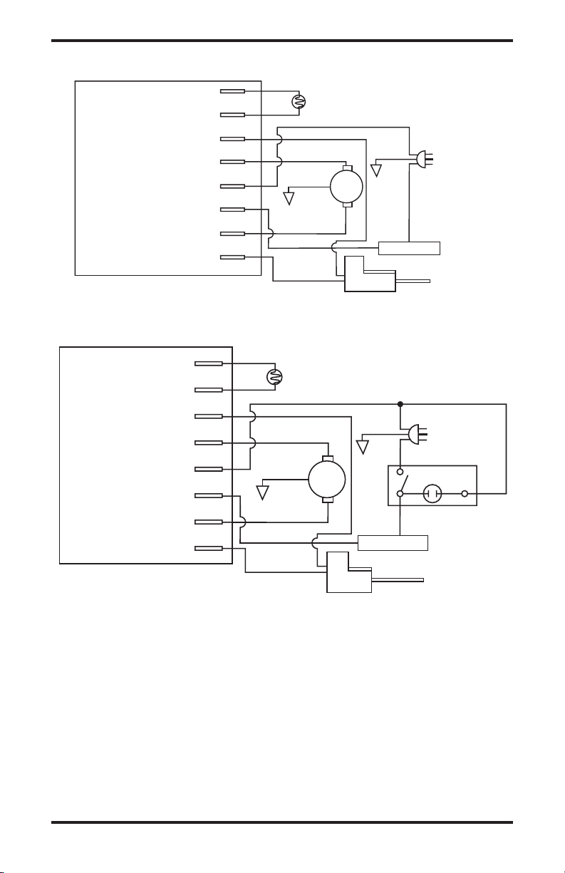
Bleu
Bleu
Blanc
Blanc
Assemblage de la commande de l’allumeur
Vert
Vert
Rouge
Noir
Noir
Noir
Jaune
Jaune
Thermostat
Cellule photoélectrique
Cellule photoélectrique
Cellule photoélectrique
Allumeur
Allumeur
Retour du moteur
C.A. neutre (L2)
120V (L1)
Allumeur
Moteur
Moteur
Interrupteur de
marche/arrêt
avec voyant
2
1
3
Prise de courant
120 V/60 Hz
Prise de courant
120 V/60 H
z
Bleu
Bleu
Blanc
Blanc
Cellule photoélectrique
Assemblage de la commande
de l’allumeur
Vert
Ve
rt
Rouge
Noir
Noir
Jaune
Jaune
Moteur
Allumeur
Thermostat
Cellule photoélectrique
Cellule photoélectrique
Allumeur
Retour du moteur
C.A. neutre. (L2)
120 V (L1)
Allumeur
Moteur
DIAGRAMMES DE CÂBLAGE
(modèles 40)
(Modèles 55/70/115/155/165)
Figure 33 - Diagramme de câblage
116170-01A 25
www.desatech.com

ACCESSOIRES
Les accessoires et pièces de l'appareil de chauffage
sont disponibles chez votre revendeur local. Si
votre revendeur ne dispose pas d' un accessoire
ou d'une pièce spécifique en stock ou est dans
l'impossibilité d'en commander, veuillez contacter
DESA Industries pour plus d'informations.
DESA Industries of Canada, Inc.
2220 Argentia Road, Unit #4
Mississauga, Ontario L5N 2K7
Parts Department
1-905-826-8010
PRÊT-À-MONTER DE LA JAUGE
D'AIR - HA1180
Pour tous les modèles. Outil spécial pour vérifier
la pression de la pompe.
PRÊT À MONTER POUR
THERMOSTAT - HA1210
Pour le modèle 40. Garde la température de
votre bâtiment suivant votre sélection jour et nuit.
Permet de faire des économies de carburant.
ASSEMBLAGE DE LA COMMANDE
D'ALLUMAGE/TEST DE CELLULE
PHOTOÉLECTRIQUE - HA1170
Outil spécial utilisé pour tester l'assemblage
de la commande d'allumage et de la cellule
photoélectrique.
PRÊT-À-MONTER DE ROUES ET DE
POIGNÉE RENFORCÉES - HA1202
Pour service intensif. Pour que votre appareil de
chauffage soit encore plus pratique et portable.
pour les modèles 40/55/70.
26 116170-01A
www.desatech.com

NOTES
______________________________________________________
______________________________________________________
______________________________________________________
______________________________________________________
______________________________________________________
______________________________________________________
______________________________________________________
______________________________________________________
______________________________________________________
______________________________________________________
______________________________________________________
______________________________________________________
______________________________________________________
______________________________________________________
______________________________________________________
______________________________________________________
______________________________________________________
______________________________________________________
______________________________________________________
______________________________________________________
______________________________________________________
______________________________________________________
______________________________________________________
______________________________________________________
______________________________________________________
______________________________________________________
______________________________________________________
______________________________________________________
______________________________________________________
______________________________________________________
______________________________________________________
______________________________________________________
______________________________________________________
______________________________________________________
______________________________________________________
116170-01A 27
www.desatech.com

SERVICE DE GARANTIE ET DE RÉPARATION
116170 01
CONSERVEZ CETTE GARANTIE
Numéro de modèle
Numéro de série
Date de l'achat
GARANTIES LIMITÉES POUR LES PRODUITS NEUFS
ET LES PRODUITS REMIS EN ÉTAT
Nouveaux produits :DESA Industries garantit que cet appareil de chauffage et ses pièces sont exempts de défauts
de matériaux et de fabrication et ceci pour une durée d'un (1) an à partir de la date du premier achat, lorsque
l'appareil de chauffage est utilisé et entretenu en conformité avec les instructions du fabricant. Ces garanties ne
protègent que l'acheteur au détail d'origine, lorsqu'une preuve d'achat est fournie.
Appareils de chauffage remis en état : DESA Industries garantit que cet appareil de chauffage remis en état en usine
et ses pièces sont exempts de défauts de matériaux et de fabrication et ceci pour une durée de trente (30) jours à partir
de la date du premier achat, lorsque l'appareil de chauffage est utilisé et entretenu en conformité avec les instructions
du fabricant. Ces garanties ne protègent que l'acheteur au détail d'origine, lorsqu'une preuve d'achat est fournie.
Ces garanties ne couvrent que le coût des pièces et de la main d'œuvre requis pour restaurer le produit à son état
de fonctionnement normal. Le transport et les frais incidents associés aux réparations sous garantie ne sont pas
remboursables sous cette garantie.
Les réparations sous garantie sont disponibles seulement par l'intermédiaire des revendeurs et des centres de
service autorisés.
Cette garantie ne couvre pas les défauts causés par la mauvaise utilisation, l'abus, la négligence, les accidents, le
manque d'entretien adéquat, l'usure normale, les modifications, les altérations, les combustibles contaminés, les
réparations avec des pièces autres que des pièces DESA ou une réparation par quelqu'un d'autre qu'un revendeur ou
un centre de service autorisé. L'entretien de routine est la responsabilité du propriétaire.
CETTE GARANTIE EXPRESSE REMPLACE TOUTE AUTRE GARANTIE EXPRESSE OU IMPLICITE, Y
COMPRIS LES GARANTIES DE COMMERCIALITÉ ET D'ADÉQUATION À UN BESOIN PARTICULIER.
DESA Industries n'assume aucune responsabilité pour des dommages indirects, imprévus ou incidents. Certains
états ou provinces ne permettent pas l'exclusion ou la restriction des dommages imprévus ou incidents et certaines
restrictions ou exclusions pourraient ne pas s'appliquer à votre cas. Cette garantie limitée vous donne des droits
spécifiques selon la loi; vous pourriez aussi avoir d'autres droits selon la province où vous habitez.
RÉPARATION SOUS GARANTIE
Si votre appareil de chauffage a besoin de réparation, retournez-le au centre de service autorisé le plus près de chez
vous. Une preuve d'achat doit être présentée avec l'appareil de chauffage. L'appareil de chauffage sera inspecté. Un
défaut peut être causé par des matériaux défectueux ou un défaut de fabrication. Si tel est le cas, DESA Industries
acceptera de réparer l'appareil de chauffage sans frais.
SERVICE DE RÉPARATION
Retournez l'appareil de chauffage au centre de service autorisé le plus près de chez vous. Chaque centre de service
est autonome. Les réparations non couvertes par la garantie seront facturées aux prix normaux. Nous nous réservons
le droit de modifier ces spécifications à tout moment sans préavis.
Des listes illustrées de pièces peuvent être obtenues sans frais. Envoyez une enveloppe-réponse affranchie à l'adresse
indiquée plus bas. Indiquez le numéro de modèle de l'appareil de chauffage et la date inscrits au coin inférieur droit de cette
page. Un guide de réparation peut être acheté à l'adresse ci-dessous. Envoyez un chèque de 5,00 $ à DESA Industries.
Lorsque vous nous écrivez pour obtenir des renseignements concernant votre appareil de chauffage, veillez à inclure
les numéros de modèle et de série qui sont inscrits sur la plaque signalétique de l'appareil.
Imprimé aux
États-Unis
NOT A UPC
2220 Argentia Road, Unit #4
Mississauga, Ontario L5N 2K7
(905) 826-8010
Télécopieur (905) 826-8236
116170-01
Rev. A
02/05
 Loading...