

VENTED PORTABLE FORCED AIR HEATER
OWNER’S MANUAL
MODELS: 160-IF, 280-IF
IMPORTANT: Read and understand this manual before
assembling, starting or servicing heater.
Improper use of heater can cause serious injury. Keep
this manual for future reference.
TABLE OF CONTENTS
Safety Information ............................................... 2
Unpacking .......................................................... 3
Product identification ........................................... 3
Fuels .................................................................... 4
To Start Heater ....................................................
Stop Heater .................................................... 4
To
Thermostat Operation ......................................... 4
Moving and Transporting Heater ......................... 4
Save this manual for future reference.
For more information, visit www.desatech.com
Preventative Maintenance ................................... 5
Troubleshooting ................................................... 5
Diagrams ............................................................. 7
Illustrated Parts Breakdown and Parts List ....... 10
Specifications ....................................................
4
Technical Service ..............................................
Accessories ....................................................... 15
Warranty and Repair Service ............................ 16
15
15
SAFETY INFORMATION
WARNING: This product contains and/or generates chemicals
known to the State of California
to cause cancer or birth defects
or other reproductive harm.
IMPORTANT: Read this owner’s
manual carefully and completely
before trying to assemble,
operate or service this heater.
Improper use of this heater can
cause serious injury or death
from burns, fire, explosion,
electrical shock and carbon
monoxide poisoning.
DANGER: Carbon monoxide
poisoning may lead to death!
Carbon Monoxide Poisoning: Early signs of carbon
monoxide poisoning resemble the flue, with head
aches, dizziness and/or nausea. If you have these
signs, the heater may not be working properly. Get
fresh air at once! Have heater serviced. Some people
are more affected by carbon monoxide than others.
These include pregnant women, persons with heart
or lung disease or anemia, those under the influence
of alcohol and those at high altitudes.
Make certain you read and understand all warnings. Keep this manual for reference. It is your
guide to safe and proper operation of this heater.
1. Use only kerosene, #1#2 diesel/fuel oil, JET A
or JP-8 fuels to avoid risk of fire or explosion.
Never use gasoline, naphtha, paint thinners,
alcohol or other highly flammable fuels.
2. Fueling
a) Personnel involved with fueling shall be
qualified and thoroughly familiar with the
manufacturerʼs instructions and applicable
regulations regarding the safe fueling of
heating units.
b) Only the type of fuel specified on the
heaterʼs data plate shall be used.
c) All flame, including the pilot light, if any,
shall be extinguished and the heater al
lowed to cool, prior to fueling.
d) During fueling, all fuel lines and fuel-line
connections shall be inspected for leaks.
Any leaks shall be repaired prior to return
ing the heater to service.
2
www.desatech.com
e) At no time shall more than one dayʼs supply
of heater fuel be stored inside a building in
the vicinity of the heater. Bulk fuel storage
shall be outside the structure.
f) All fuel storage shall be located a minimum
of 25 feet (762cm) from heaters, torches,
welding equipment and similar sources
of ignition (exception: the fuel reservoir
integral with the heater unit).
g) Whenever possible, fuel storage shall be
confined to areas where floor penetrations
do not permit fuel to drip onto or be ignited
by a fire at lower elevation.
h) Fuel storage shall be in accordance with
the authority having jurisdiction.
3. Use only the electrical voltage and frequency
specified on model plate.
4. Heater must be grounded. Use only a properly
grounded three-wire extension cord. Plug into
grounded outlet only.
5. Use only in areas free of flammable vapors or
high dust content.
6. Minimum clearance from any combustible
materials: 8 feet (244 cm) from hot air outlet;
4 feet (122 cm) from top; and 4 feet (122 cm)
from sides and inlet.
7. Locate heater on a stable and level surface
while hot or operating or a fire may occur.
8. Use only in well-vented areas. Before using
heater, provide at least a three-square-foot
(2800 square cm) opening of fresh, outside air
for each 100,000 Btu/Hr (30 kw) of rating.
9. Keep children and animals away from heater
at all times.
10. Never start heater when combustion chamber
is hot or if fuel has accumulated in combustion
chamber.
11. When used with thermostat, heater may start
at anytime.
12. When heater is moved or stored, it must be in
a level position or fuel spillage may occur.
13. Use heater only in accordance with local
ordinances and codes.
14. Never use gasoline, crankcase drainings,
naphtha, paint thinners, alcohol or other highly
flammable fuels.
15.
Never use heater where gasoline, paint thinner
or other highly flammable vapors are present.
-
16. Never use heater in living or sleeping areas.
17. Never leave a heater plugged in without adult
supervision if children or animals are likely to
be present.
-
114909-01A
SAFETY INFORMATION
Continued
18. Never move, handle, refuel or service a hot,
operating or plugged-in heater.
19. Never attach heater to external fuel tank.
20. Heaters used in the vicinity of tarpaulins,
canvas or similar enclosure materials shall be
located a safe distance from such materials.
The recommended minimum safe distance is
10 feet (304.8cm). It is further recommended
that these enclosure materials be of a fire
retardant nature. These enclosure materials
shall be securely fastened to prevent them
from igniting or from upsetting the heater due
to wind action.
21. Unplug heater when not in use.
22. Never block air inlet (rear) or air outlet (front)
of heater.
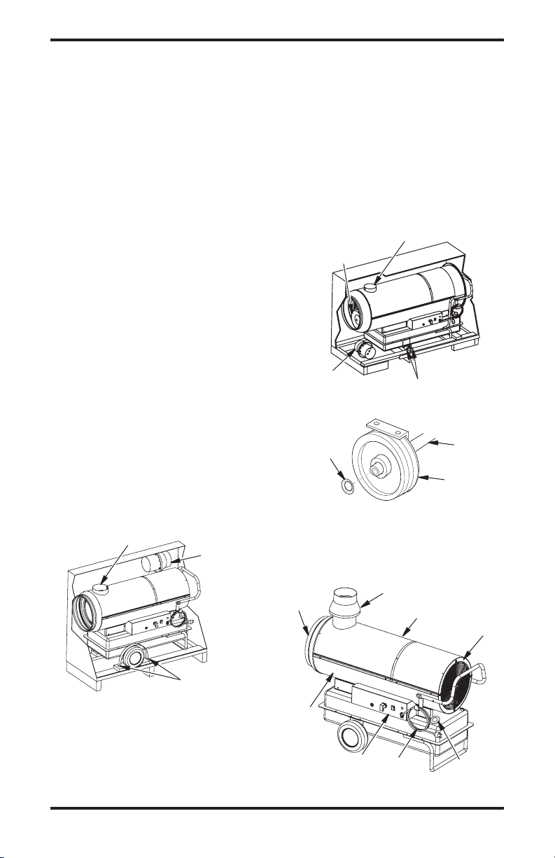
UNPACKING
MODEL 160-IF
1. Remove all the materials used to package the
heater for shipment.
2. Open the carton from the top.
3. Remove the flue connection from carton (see
Figure 1).
4. Lift up and remove cardboard packaging.
5. Unscrew the locking screws on wheel-lock
straps (see Figure 1).
6. Insert the flue connection onto the flue outlet
tube (see Figure 4).
7. Carefully lower the heater from pallet.
Flue Outlet
Tube
Flue
Connection
4. Unscrew the locking screws on hub locking
bar (see Figure 2).
5. Remove the wheels from the hot air outlet
(stored for shipping).
Lift the heater from the air outlet end.
6.
7. Insert the wheels onto the axle.
8. Insert the locking washer (which is in the
documentation envelope) with the convex side
towards the exterior of the machine; using a
hammer and an appropriate-sized spanner, tap
it gently to fix it into position (see Figure 3).
9. Carefully lower the heater from pallet.
Wheels Stored
for Shipping
Flue
Connection
Figure 2 - Removing 280-IF from Carton
Lock
Washer
Figure 3 - Wheel/Axle Assembly for
Flue Outlet Tube
Locking Screws
Axle
Wheel
280-IF
PRODUCT
IDENTIFICATION
Locking Screws
Figure 1 - Removing 160-IF from Carton
MODEL 280-IF
1. Remove all the materials used to package the
heater for shipment.
2. Open the carton from the top.
3. Lift up and remove cardboard packaging.
www.desatech.com
Hot Air
Output
Lower
Shell
Control
Panel
Figure 4 - Vented Portable Forced Air Heater
Flue Connection
Upper
Shell
Power
Cable
Fan
Guard
Fuel Tank
Cap
3114909-01A
FUELS
WARNING: Use only kerosene, #1/#2 diesel/fuel oil, JET A
or JP-8 fuels to avoid risk of fire or
explosion. Never use gasoline, oil
drained from crankcases, naphtha, paint thinners, alcohol or
other highly flammable fuels.
Use only kerosene, #1/#2 diesel/fuel oil, JET A
or JP-8 fuels. Heavier fuels such as No. 2 fuel
oil or No. 2 diesel fuel may also be used but will
result in:
• noticeable odor
• additional fuel filter maintenance
• the need for nontoxic, anti-icer additives in very
cold weather
Do not use fuels heavier than No. 2 grade or
heavy oils such as oil drained from crankcases.
These heavy oils will not ignite properly and will
contaminate the heater.
IMPORTANT: Use a KEROSENE ONLY (blue)
or DIESEL ONLY (yellow) storage container. Be
sure storage container is clean. Foreign matter
such as rust, dirt or water will cause the ignition
control assembly to shut down heater. Foreign
matter may also require heaterʼs fuel system to
be frequently cleaned.
TO START HEATER
IMPORTANT: Review and understand the warnings in the
Information section, page 2. They
are needed to safely operate
this heater. Follow all local ordinances and codes when using
this heater.
1. Fill tank with fuel (see Fuels).
2.
Plug heater power cord into approved, grounded,
120V/60Hz, 3 prong outlet or extension cord.
Extension Cord Size Requirements
6 to 10 feet (1.8 to 3 meters) long, use 18 AWG
(0.75 mm2) rated cord
11 to 100 feet (3.3 to 30.5 meters) long, use
16 AWG (1.0 mm
101 to 200 feet (30.8 to 61 meters) long, use
14 AWG (1.5 mm
3. If a thermostat is connected, adjust it to the
maximum temperature.
2
) rated cord
2
) rated cord
Safety
4.
Flip switch (3 on Electric Control Panel,
page 7) to the position with the symbol:
- the fan should start and after several
seconds the heater should ignite.
The first time the heater is used or after the fuel
circuit has been completely drained, the flow of
fuel oil to the nozzle may be insufficient and may
activate the flame control, which will turn off the
heater; if this happens, wait for about a minute and
then press the reset button (1
Panel, page 7
) to start the heater again.
on Electric Control
TO STOP HEATER
1.
Move switch (3 on Electric Control Panel, page
7) to the “0” position or adjust the control mech
anism, for example turning the thermostat to a
lower position. The flame will go out and the fan
will continue to function until the combustion
chamber has cooled down completely.
2. Wait until fan stops before unplugging heater.
Unplug heater when not in use.
THERMOSTAT
OPERATION
The heater can only work automatically when a
thermostat is connected to it by attaching the cable
to terminals 2 and 3 of plug (4
Panel, page 7
).
on Electric Control
MOVING AND
TRANSPORTING HEATER
WARNING: Before moving
the heater you must turn the
heater off (see To Stop Heater),
disconnect the plug from the
power supply and wait for the
heater to cool.
Before lifting or moving the heater, make sure that
the fuel tank cap is firmly in place.
The heater may be supplied in a portable version,
with wheels or a suspended version, mounted on a
support structure and fixed in place with wires or
chains. In the former case, to move the heater, sim
ply grasp the support handle and move the heater.
In the latter case, the heater must be lifted with a
fork-lift truck or a similar piece of equipment.
-
-
4
www.desatech.com
114909-01A
PREVENTATIVE
MAINTENANCE
To ensure that the heater continues to work
properly, it is necessary to periodically clean the
combustion chamber, the burner and the fan.
WARNING The following
steps must be carried out before
servicing the heater: turn the
heater off, following the instruc
tions in the previous section;
disconnect the plug from the
power supply and wait for the
heater to cool.
TROUBLESHOOTING
OBSERVED FAULT
The fan does not come on and
the flame does not light
POSSIBLE CAUSE
1. No electric current
2. Incorrect setting on the thermo
stat (if fitted)
3. Faulty thermostat
4. Motor winding burnt out or
broken
5. Bearings of motor have seized
up
6. Motor capacitor has burned
out
7. Thermostat plug not connected
Every 50 hours of use it is necessary to:
• Dismantle the filter cartridge, remove it and
clean it with clean fuel oil.
• Remove the exterior cylindrical casing and
clean the inside and the blades of the fan.
• Check the condition of the cables and the high
voltage connections on the electrodes.
• Dismantle the burner, clean the parts, then clean
the electrodes and adjust them, if necessary, to
the distance indicated in Electrode Spacing on
page 7.
SOLUTION
1
A) Check the characteristics
of the electrical system (120 V
- 60 Hz)
B) Check that the sw itch
works and is in the correct
position
C) Check that the fuse has not
blown
-
2. Check that the thermostat
setting is correct (e.g. the
temperature setting on the
thermostat must be higher than
the ambient temperature)
3.
Replace the thermostat
4. Replace the motor
5. Replace the bearings
6. Replace the capacitor
7. Connect thermostat plug
www.desatech.com
5114909-01A

OBSERVED FAULT
The fan comes on but the
flame does not light or does
not remain lit
TROUBLESHOOTING
Continued
POSSIBLE CAUSE
1. Ignitor is not functioning
2.
Faulty flame control
3.
Non-functioning photoelectric
cell
4. Fuel is not reaching the burner
or a sufficient amount is not
arriving
5.
Solenoid valve is not working
SOLUTION
1. A) Check the connections
of the ignition cables to the
electrodes and transformer
B) Check the position of the
electrodes and the distance
between them, in accordance
with the diagram on page 7
C) Check that the electrodes
are clean
D) Replac e the ignit ion
transformer
2. Replace the flame control
3. Clean or replace the photoelectric cell
4. A) Check that the connection
between the pump and the
motor is intact
B) Check that air has not filtered into the fuel circuit, check
the tubes and the filter seal
C) Clean or, if necessary,
replace the nozzle
5. A) Check the electrical con
nection
B) Check the LI thermostat
C) Clean or, if necessary,
replace the solenoid valve
-
The fan comes on and the flame
lights, but produces smoke
The heater does not turn off
The fan does not switch off
6
1.
Insufficient air for combustion
2. Too much air for combustion
3. Fuel is dirty or contains water
4. Air has filtered into the fuel
circuit
5. Inadequate quantity of fuel in
burner
6. Too much fuel in burner
1. Faulty fan thermostat
www.desatech.com
1. A) Remove anything block
ing or obstructing the aspiration and/or airflow ducts
B) Check the position of the
air regulation ring
C) Clean the burner disc
2. Check the position of the air
regulation ring
3. A) Replace the fuel with
clean fuel
B) Clean the fuel filter
4. Check the condition of the
tubes and the seal of the fuel
filter
5. A) Check the pump pressure
B) Clean or replace the nozzle
6.
A) Check the pump pressure
B) Replace the nozzle
1. Replace the solenoid valve
1. Replace the FA thermostat
114909-01A
-
DIAGRAMS
1 2 3 6 8 9
12
13
11
4
5 7
10
0.08" - 0.12"
(2-3 mm)
!
C
A
UT
IO
N
:
H
o
t
w
h
i
le
i
n
o
pe
rati
o
n
.
D
o
n
o
t
to
u
c
h.
Ke
e
p
c
h
il
d
ren,
a
n
im
a
ls
,
c
lo
th
in
g
a
n
d
c
o
m
b
us
t
i
bl
e
s
aw
a
y.
!
P
R
E
CA
UC
I
Ó
N:
C
al
ie
n
te
cu
a
nd
o
e
s
t
á
en
o
p
e
r
ac
ió
n
.
No
t
ocar
.
M
a
n
te
n
g
a
a lo
s
n
iñ
o
s
,
a
ni
m
a
l
e
s
,
v
e
s
t
im
e
nt
a
y
c
om
b
u
s
ti
b
l
es
a
le
-
j
ad
o
s.
!
AT
T
E
N
T
IO
N
:
L’
ap
pa
re
i
l
de
c
hauffage
e
s
t
b
rû
la
n
t
p
en
d
a
n
t
l
e
fo
n
c
t
i
o
n
ne
m
e
nt.
N
e
le
to
u
c
he
z
p
a
s
.
T
e
n
e
z
l
es
e
n
fa
n
ts
, les
a
nim
a
u
x
e
t
l
es
vê
t
e
m
e
n
t
s
à
l’
é
c
ar
t
d
e
c
e
t
ap
p
a
re
il
.
O
P
E
R
A
T
IN
G
I
N
S
T
R
U
C
T
IO
N
S
ST
A
RT
1
.
Fill
t
a
nk
U
se
o
nl
y
ke
ro
se
n
e
,
#
1
&
#
2
d
ie
se
l
a
n
d
f
u
el
o
il
,
JE
T
A
o
r
JP
8
f
ue
l
s.
2
.
P
lu
g
p
ow
e
r
cord
i
n
to
12
0V
/6
0
Hz
outl
et
.
Po
w
e
r
in
d
icator
lig
h
t
sh
o
ul
d
be
on
.
3
.
If
e
q
u
ip
pe
d
, ad
j
us
t th
e
r
m
o
s
ta
t
k
no
b
to
t
he wa
rm
es
t
sett
i
ng
.
4
.
P
u
s
h
ON
/
OF
F
sw
itch
t
o
O
N
( )
.
F
a
n
m
o
to
r
sh
ou
ld
s
t
ar
t
i
mm
e
d
ia
t
e
ly
.
He
a
te
r
wi
l
l
i
gn
i
te
wi
th
i
n
1
0
s
econds
.
5
.
If
eq
ui
p
pe
d,
ad
j
u
s
t
th
e
rm
osta
t to desired
s
etti
n
g
.
ST
OP
Pu
s
h
O
N
/
O
F
F
sw
it
c
h
to
OF
F
(
O).
F
a
n
m
o
to
r
wi
l
l
cont
i
n
u
e
to
r
u
n.
Do
n
o
t
un
plug he
a
te
r
u
n
t
i
l
c
o
o
l
in
g
c
y
cl
e
i
s
c
o
mp
l
e
te.
S
e
e
m
o
d
e
l
d
e
c
a
l
o
r
o
w
n
er
’s
m
a
n
u
a
l
f
or
a
d
d
i
t
io
n
a
l
o
p
e
r
a
t
i
n
g
i
n
s
t
r
u
c
-
t
io
n
s
,
s
a
fe
t
y
r
e
q
u
i
r
e
m
e
n
t
s
,
a
n
d
s
p
e
c
i
fi
c
a
t
i
o
n
s
.
O
PE
R
A
T
I
N
G
I
N
S
T
R
U
C
T
I
O
N
S
ST
A
R
T
1
.
Fill
t
a
n
k
U
se
o
nl
y
ker
os
e
n
e
,
#
1
&
#
2
d
ie
s
el
a
n
d
f
u
e
l
o
i
l
,
JE
T
A
o
r
JP
8
f
u
e
l
s.
2
.
P
lu
g
p
o
we
r
co
r
d
in
t
o
1
2
0V
/
6
0
H
z
o
u
t
le
t.
P
ow
er
i
n
d
icator
ligh
t
should
be
on
.
3
.
If
e
q
u
ip
pe
d
, adju
s
t
t
he
r
m
os
ta
t kn
o
b
to
t
he
warmes
t
se
t
t
i
n
g
.
4
.
P
u
sh
ON
/OFF
sw
it
ch
t
o
ON
(
)
. Fa
n
mo
t
or
s
h
o
u
ld
st
a
r
t
i
mm
e
di
-
a
tely
. He
a
te
r
wi
l
l
i
gn
i
te
wi
th
i
n
1
0
se
co
n
ds
.
5
.
If
eq
ui
p
pe
d, ad
j
us
t
ther
m
o
st
at
to desir
e
d sett
i
ng
.
ST
OP
Pu
s
h
O
N
/
O
F
F
s
w
i
t
c
h
to OF
F
(
O
)
.
F
an
mo
t
or
wi
l
l
co
n
ti
n
u
e
to
r
u
n.
Do
n
o
t
u
n
plug
h
e
a
te
r
u
nt
i
l co
o
l
in
g
c
y
cl
e
i
s
c
om
p
l
e
te
.
Se
e
mo
d
el
d
e
c
a
l
or
o
w
n
er
’
s
m
a
n
u
a
l
f
or
a
d
d
it
i
o
n
a
l
o
p
er
at
i
n
g
in
st
r
u
c
-
t
io
n
s
,
s
a
fe
t
y
r
e
q
u
i
r
e
m
e
n
t
s
,
an
d
s
p
e
c
i
fi
c
a
t
i
o
n
s
.
O
PE
R
A
T
I
N
G
IN
S
TR
U
C
T
IO
NS
ST
A
RT
1.
Fi
l
l
t
a
n
k
Us
e
o
nl
y
ke
r
ose
ne
,
#
1
&
#
2
d
iese
l
a
n
d
f
u
el
o
il
,
JET
A
o
r
JP-8
f
u
e
ls
.
2.
P
lu
g
p
ow
e
r
co
rd
in
t
o
1
2
0
V
/
6
0
Hz
o
u
t
le
t
.
Po
w
e
r
i
n
d
i
ca
to
r
li
gh
t
s
h
ou
l
d
be
o
n.
3.
If
eq
ui
p
pe
d
,
a
d
ju
s
t
the
rm
os
t
at
k
n
ob
to the
wa
r
m
es
t
sett
i
ng
.
4
.
P
us
h
ON
/
OF
F
sw
it
ch
t
o
ON ( )
.
F
an
mo
t
or
should
st
a
r
t
i
mm
e
d
i
-
ate
l
y
. He
at
e
r
wi
l
l
i
g
n
i
te
wi
t
hi
n
1
0
s
econ
d
s
.
5
.
I
f
e
q
u
i
p
pe
d,
ad
j
us
t
t
he
r
m
os
tat
t
o
d
esired
s
e
tt
i
n
g
.
S
T
OP
Pu
s
h
ON/O
F
F
swit
c
h
to
OFF
(
O
).
F
a
n
moto
r
wi
l
l
c
o
n
t
in
u
e
t
o
r
u
n.
Do
no
t
u
np
l
u
g
he
at
e
r
un
ti
l
c
o
ol
i
n
g
cy
c
le
is
c
o
mp
l
e
t
e
.
S
e
e
m
o
d
e
l
d
e
c
a
l
or
o
w
ne
r
’
s
m
a
n
u
a
l
f
or
a
d
d
it
io
n
a
l
o
pe
r
a
t
i
ng
i
n
s
t
r
u
c
-
t
i
o
n
s
,
s
a
fe
ty
r
e
qu
i
r
e
m
e
n
t
s,
a
n
d
s
pe
c
i
fic
a
t
i
o
n
s
.
2
7
0
0
1
I
n
d
us
t
ri
a
l
D
ri
v
e
P.
O
.
B
o
x
9
00
4
Bo
wl
i
n
g
G
r
e
en
,
K
y
4
2
1
0
2
w
ww
.
d
e
s
at
e
c
h
.
co
m
1
13
3
44
-0
8
U
N
PL
U
G
HE
A
T
E
R
B
E
F
O
R
E
R
E
M
O
V
I
NG
CO
VE
R
U
N
P
LU
G
HE
A
T
E
R
B
E
F
O
RE
R
E
M
O
V
I
N
G
CO
V
ER
U
N
P
L
U
G
HE
A
T
E
R
B
E
F
O
R
E
RE
M
OV
I
N
G
C
OV
E
R
Ma
de
i
n
I
t
a
l
y
FLA
M
E
C
O
N
TRO
L
R
E
S
E
T
F
LA
M
E
CO
N
TR
O
L
R
E
S
E
T
FLA
M
E
C
O
N
T
RO
L
R
E
S
E
T
M
a
n
uf
ac
t
u
re
d
f
o
r
:
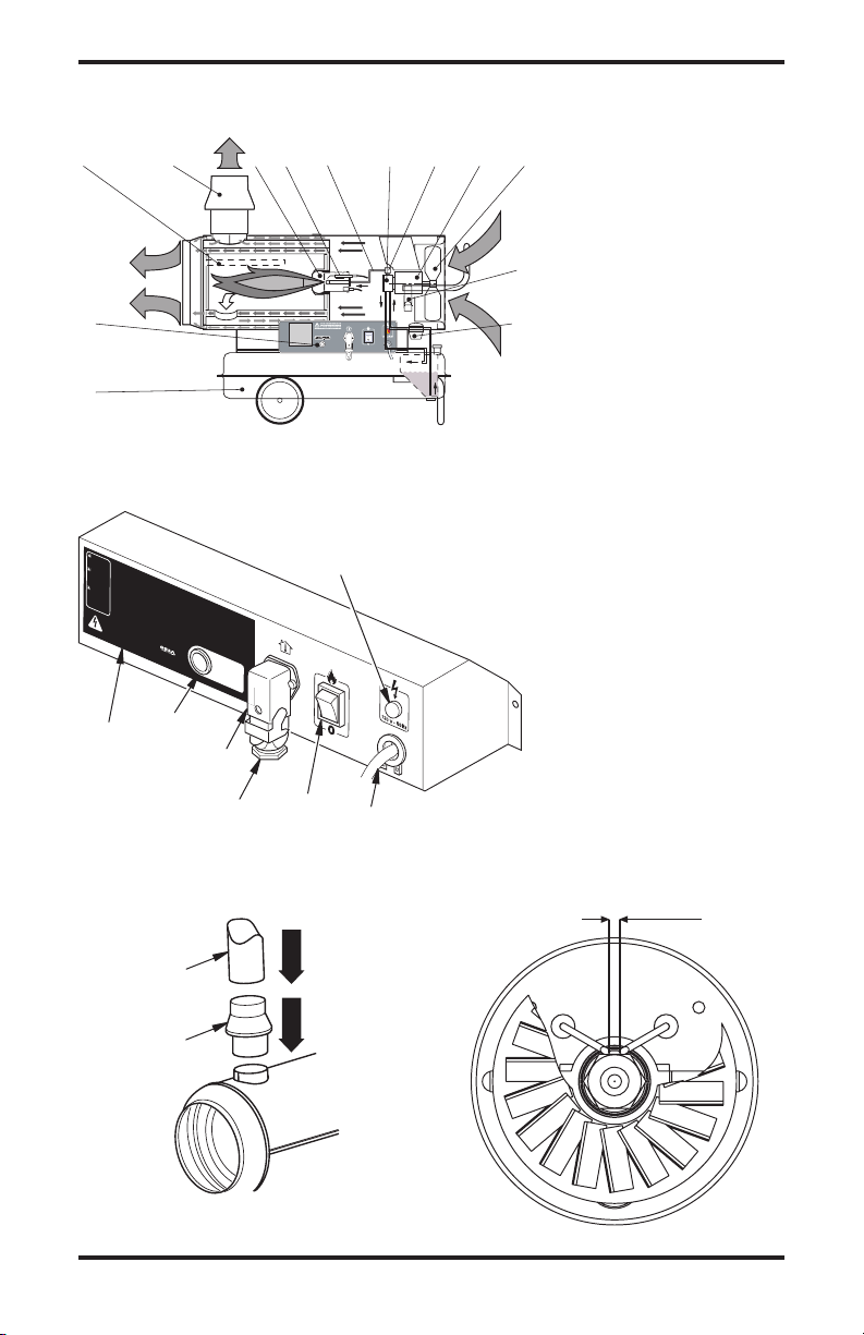
HEATER FUNCTIONING DIAGRAM
1. Combustion chamber
2. Anti-wind flue connection
3. Burner
4. Nozzle
5. Fuel circuit
6. Fuel pump
7. Electric fuel valve
8. Motor
9. Fan
10. Cable winding bracket
11. Fuel filter
12. Fuel tank
13. Control panel
ELECTRIC CONTROL PANEL
1. Reset button
6
1
2
4
2. Operation label
3. Main switch
4. Socket for ambient ther
mostat
5. Power cable
6. Power indicator
7. Thermostat plug (must be
secure if no control device
is used)
-
7
3
5
FLUE CONNECTIONS DIAGRAM
Pipe 6" Diameter
Flue
Connector
www.desatech.com
ELECTRODE SPACING
7114909-01A
DIAGRAMS
5
4
A
3
2
D
C
1
B
A
6
2
D
C
1
B
5
E
Continued
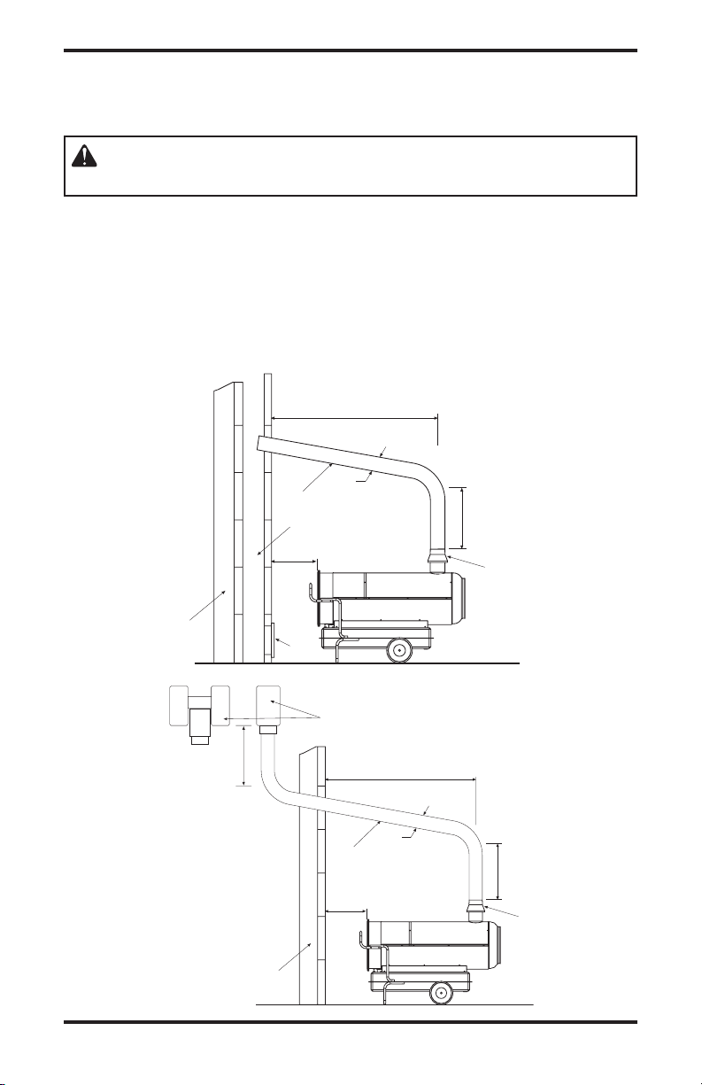
EXHAUST PIPE POSITIONING DIAGRAM
WARNING: The diagrams are typical; the installation of the flue
must meet current legal norms.
A. Minimum 3 ft.
B. Minimum 3 ft.
C. As short as possible
D. Equal to or greater than the diameter of
the burner’s flue output
E. Minimum 3 ft.
1. Anti-wind device fitted with the heater
2. Horizontal crosspiece with a minimum
upwards angle of at least 5°, minimum 1"
up for every 12" of horizontal travel
3. Flue with minimum internal dimensions
of 8" x 8"
4. Anti-explosion/flue inspection shutter
5. External buffer wall
6. H-shape draw activator
8
www.desatech.com
114909-01A
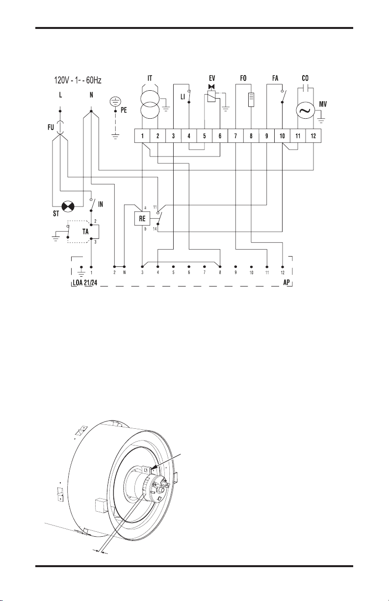
ELECTRIC WIRING DIAGRAM
A
DIAGRAMS
Continued
FU Fuse
6A 160-IF
10A 280-IF
IT High voltage transformer
LI Safety thermostat
EV Solenoid valve
FO Photocell
FA Fan thermostat
CO Capacitor
MV Fan motor
ST Power light
IN Switch
TA Ambient thermostat socket
RE Relay
AP Control box
REGULATION OF COMBUSTION AIR SHUTTER ADJUSTMENT
Air Shutter
160-IF A=19/32" (15mm)
280-IF A=5/16" (8mm)
www.desatech.com
9114909-01A
ILLUSTRATED PARTS BREAKDOWN
1
2
33
3
4
8
11
12
13
14
15
16
17
18
19
20
21
22
23
24
25
35
30
34
26
27
28
29
30
31
36
7
6
28
10
9
28
5
32
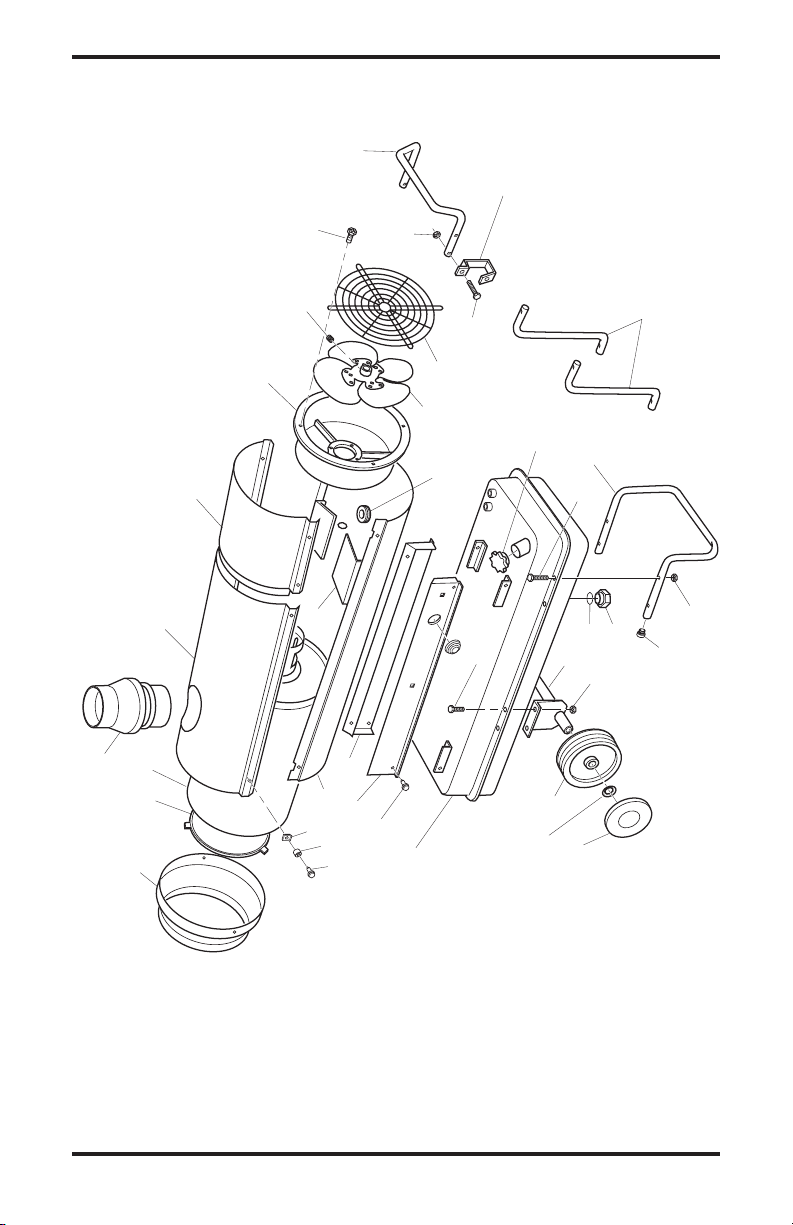
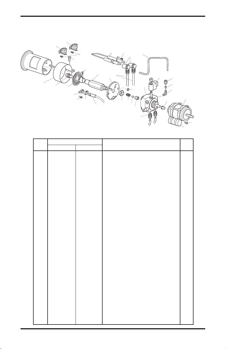
MODELS: 160-IF, 280-IF
10
www.desatech.com
114909-01A
This list contains replaceable parts used in your heater. When ordering parts, be sure to provide the correct
PARTS LIST
model and serial numbers (from the model plate), then the part number and description of the desired part.
KEY PART NUMBER
NO. 160-IF 280-IF DESCRIPTION QTY.
1 115130-01 115130-02 Rear Handle 1
2 115131-01 115131-02 Frame Support 1
3 115132-01 115132-02 Outlet Cone 1
4 115133-01 115133-01 Cap Plug 2
5 115134-01 115134-02 Axel 1
6 115135-01 115135-02 Wheel 2
7 115136-01 115136-02 Wheel Lock Washer 2
8 115137-01 115138-01 Fuel Tank 1
9 115139-01 115139-01 Drain Plug 1
10 115140-01 115140-01 Drain Plug O-Ring 1
11 115141-01 115141-01 Fuel Cap 1
12 115142-01 115142-02 Fan Guard 1
13 115143-01 115144-01 Fan 1
14 115145-01 115145-01 Fan Set Screw 1
15 115146-01 115147-01 Motor Support 1
16 115148-01 115148-02 Air Deflector 3
17 115149-01 115150-01 Combustion Chamber 1
18 115151-01 115152-01 Flame Guard Shield 1
19 115153-01 115154-01 Shell Support, Right 1
20 115155-01 115156-01 Shell Support, Left 1
21 115157-01 115158-01 Lower Shell 1
22 115159-01 115160-01 Upper Shell 1
23 115161-01 115162-01 Upper Shell, Rear Cover 1
24 115163-01 115163-01 Flue Connector 1
25 115164-01 115164-01 Cable Bushing 1
26 115165-01 115165-01 Screw, M5 x 16 4
27 115166-01 115166-01 Screw, 10 x 1/2" 6
28 115248-01 115248-01 Nut, M6 10
29 115249-01 115249-01 Sleeve Screw 6
30 115250-01 115250-01 Screw, M6 x 16 4
31 115251-01 115251-01 Screw, 14 x 1/2" 4
32 115167-01 115167-01 Clip Nut 6
33 115168-01 115168-01 Screw, M6 x 30 4
34 115169-01 115169-01 Power Cord Hook 2
35 ----- 115170-01 Handle Support Bar 2
36 115171-01 115171-02 Yellow Wheel Plug 2
114909-01A
www.desatech.com
11
1
2
3
4
5
6
7
8
9
10
11
12
13
14-1
14-2
14-3
14-4
15
16
17
18
19
20
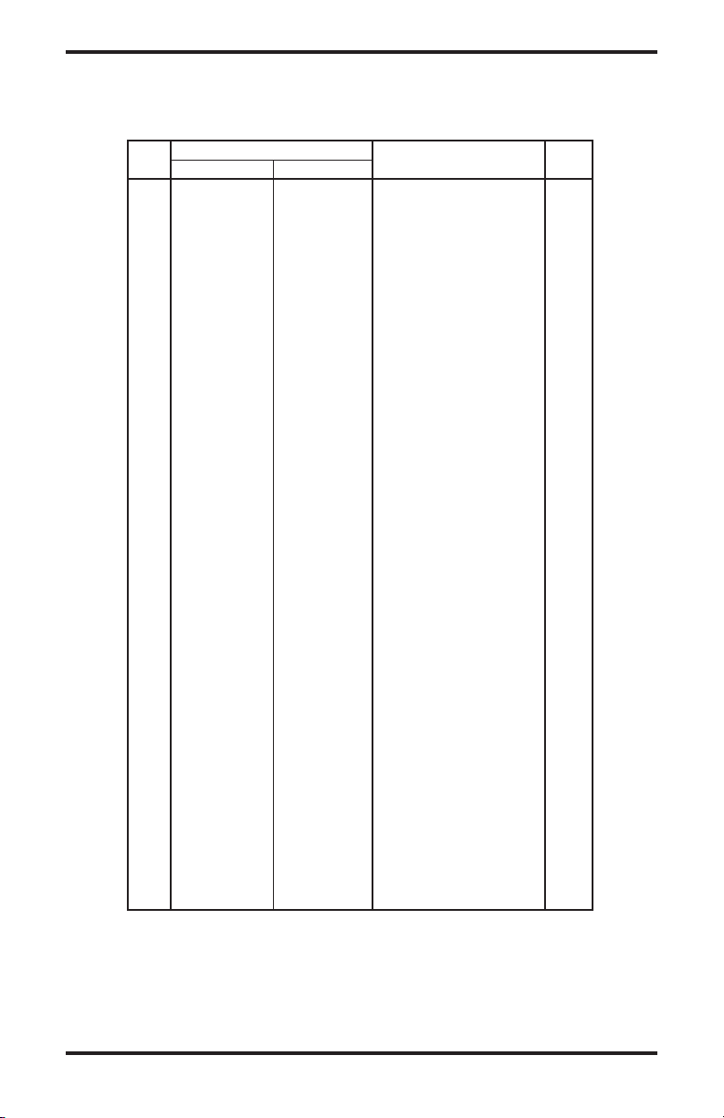
ILLUSTRATED PARTS BREAKDOWN AND PARTS LIST
CONTROL BOX FOR 160-IF, 280-IF
KEY PART NUMBER
NO. 160-IF 280-IF DESCRIPTION QTY.
1 115172-01 115172-01 Control Box Support 1
2 Control Box Base 1
3 115173-01 115173-01 Control Box 1
4 115174-01 115174-01 Transformer 120V 1
5 115175-01 115175-02 High Tension Cable 2
6 115176-01 115176-01 Relay 1
7 115177-01 115177-01 Terminal Board 1
8 115178-01 115178-01 Electrical Component Cover 1
9 115179-01 115179-01 Power Light 1
10 115180-01 115180-01 Switch Cover 1
11 115181-01 115181-01 Switch 1
12 115182-01 115182-01 4-Pin Socket 1
13 115183-01 115183-01 Plug 1
14 115184-01 115184-01 Electric Wire with Plug and
Cable Fastener 1
14-1 115185-01 115185-01 Cable Fastener 1
14-2 115186-01 115186-02 Fuse 1
14-3 115187-01 115187-01 Electric Wire with Plug 1
14-4 115188-01 115188-01 Screw 8 x 3/8" 2
15 115189-01 115189-01 Screw 8 x 1
16 115190-01 115190-01 Screw 4 x 1/2" 2
17 115191-01 115191-01 Clamp Nut M6 2
18 115250-01 115250-01 Screw M6 x 16mm 2
19 115192-01 115192-01 Screw 4 x 3/8" 2
12
www.desatech.com
1
/2" 2
114909-01A
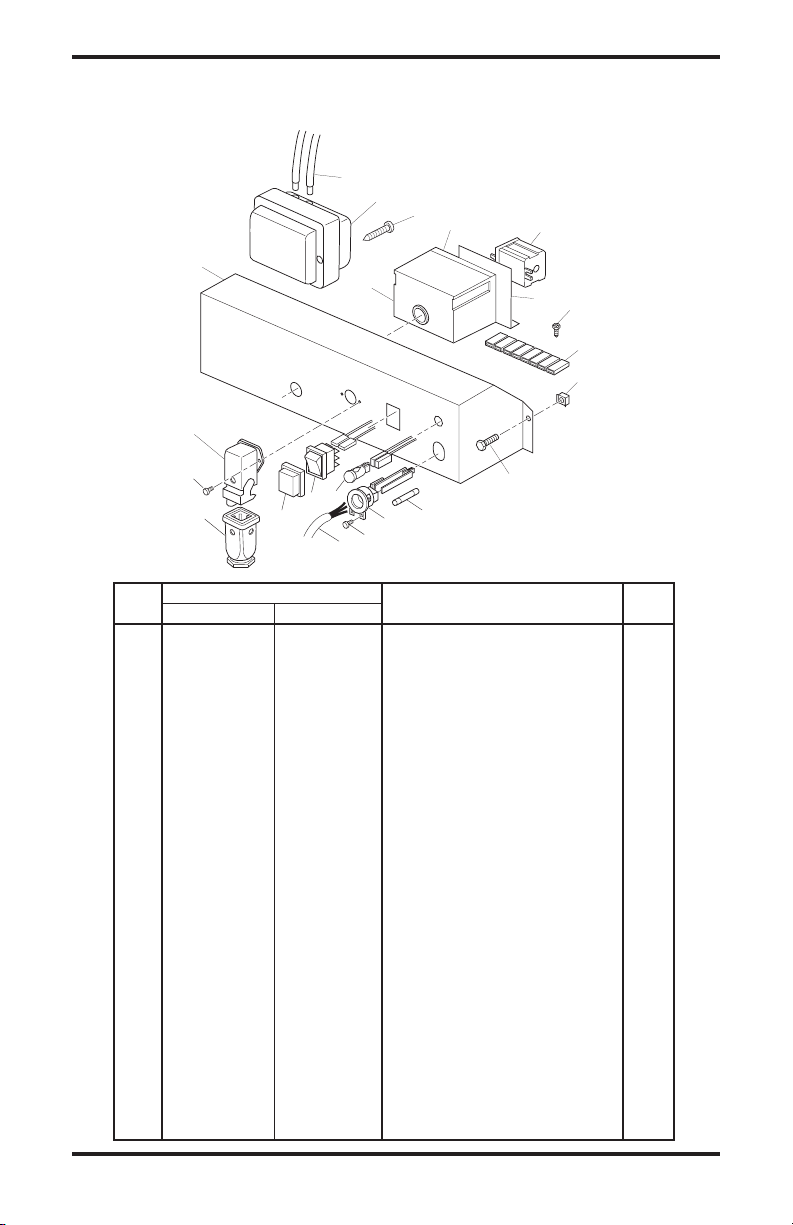
ILLUSTRATED PARTS BREAKDOWN AND PARTS LIST
1
1
2
3
4
5
6
7
8
11
11
9
10-1
10-2
10-3
10-4
10-5
FUEL FILTER ASSEMBLY FOR 160-IF, 280-IF
KEY PART NUMBER
NO. 160-IF 280-IF DESCRIPTION QTY.
1 115252-01 115252-01 Flex Fuel Tube 1
2 115253-01 115253-01 Cable Bushing 1
3 115193-01 115193-02 Fuel Pickup Tube 1
4 115194-01 115194-01 Straight Connection 1/4" 1
5 115195-01 115195-01 Nut 3/8" x 5 1
6 115196-01 115196-01 Filter Support Bracket 1
7 115197-01 115197-01 Double Male Connector 1
8 115198-01 115198-01 90˚ Elbow 1
9 115199-01 115199-01 Straight Connector 1
10 115200-01 115200-01 Filter Assembly 1
10-1 115201-01 115201-01 Filter O-Ring 1
10-2 115202-01 115202-01 Top Fuel Filter Seal 1
10-3 115203-01 115203-01 Filter Element 1
10-4 115204-01 115204-01 Filter Housing 1
10-5 115205-01 115205-01 Lower Oil Filter Seal 1
11 115206-01 115206-01 Straight Connector 1/8" 2
www.desatech.com
13114909-01A
ILLUSTRATED PARTS BREAKDOWN AND PARTS LIST
2
1
3
4
5
6
7-1
7-2
14
9
8
12
11
1516
26
17
18
29
25
25
30
19
20
10
11
12
27
13
21
24
28
23
22
Blue Mark
MOTOR, FUEL PUMP AND BURNER COMPONENTS FOR 160-IF, 280-IF
KEY PART NUMBER
NO. 160-IF 280-IF DESCRIPTION QTY.
1 115207-01 115207-02 Electrode Wire 2
2 115208-01 115208-01 Cool Off Thermostat (Fan) 1
3 115209-01 115209-01 Overheat Thermostat (Blue Dot) 1
4 115210-01 115210-01 Ceramic Electrode 2
5 115211-01 115211-01 Cable Connector (90˚) 2
6 115212-01 115212-01 Fuel Line 1
7 115213-01 115213-01 High Pressure Pump 1
7-1 115214-01 115214-01 Solenoid Valve 1
7-2 115215-01 115215-01 Pump Body/Housing 1
8 115216-01 115216-01 Connector 1/4" 2
9 115217-01 115217-02 Coupling, Motor/Pump 1
10 115218-01 115218-01 Connector 90˚ 1/8" 1
11 115219-01 115219-01 Ferrule 4mm 2
12 115220-01 115220-01 Ferrule Nut 2
13 115221-01 115222-01 Motor 1
14 115223-01 115223-01 Fuel Line Fitting 1
15 115224-01 115224-01 Connector 1/8" 1
16 115225-01 115225-01 Nut, M14 1
17 115226-01 115226-01 Burner Flange 1
18 115227-01 115227-01 Nozzle Support 1
19 115228-01 115228-01 Diffuser 1
20 115229-01 115229-02 Nozzle, 80˚ 1
21 115230-01 115230-01 Air Regulation Strap 1
22 115231-01 115231-01 Photocell 1
23 115232-01 115232-01 Photocell Clamp 1
24 115233-01 115233-01 Photocell Flange 1
25 115234-01 115234-01 Screw 8 x 3/8" 3
26 115235-01 115235-01 Nut, M5 1
27 115236-01 115236-01 Screw, Allen 1
28 115237-01 115237-01 Screw 6 x 1/2" 1
29 115238-01 115238-01 Screw M4 x 8mm, Allen 1
30 115239-01 115239-01 Screw M6 x 25mm, Allen 1
14
www.desatech.com
114909-01A
SPECIFICATIONS
Model Size 160-IF 280-IF
Maximum Output Rating (Btu/Hr) 158,000 278,000
Net Output Rating (Btu/Hr) 133,000 234,400
Fuel Use only kerosene, #1/#2 diesel/fuel oil, JET A or JP-8 fuels*
Fuel Tank Capacity (U.S. Gal./Liters) 17/65 28/105
Fuel Consumption
(Gal. Per Hr/Liters Per Hr) 1.27/4.81 2.22/8.40
Pump Pressure (psi) 145 174
Electric Requirements 120 V/60 HZ (Same Both Models)
Amperage (Normal Run) 4.8 8.5
Motor RPM 2850 3490
Hot Air Output (CFM) 1,060 1,940
Shipping Weight 190/86 320/145
(Approximate lbs./kg)
Heater Weight without Fuel 161/74 273/124
(Approximate lbs./kg)
* Use of #2 diesel & fuel oil will result in noticeable odor and could require additional fuel filter main
tenance. Use in extreme cold temperatures may require nontoxic anti-icer additives.
TECHNICAL SERVICE
You my have further questions about installation,
operation or troubleshooting. If so, contact DESA
Heating Productsʼ Technical Service Department
at 1-866-672-6040. When calling please have your
model and serial numbers of your heater ready. You
can also visit DESA Heating Productsʼ technical
services web site at www.desatech.com.
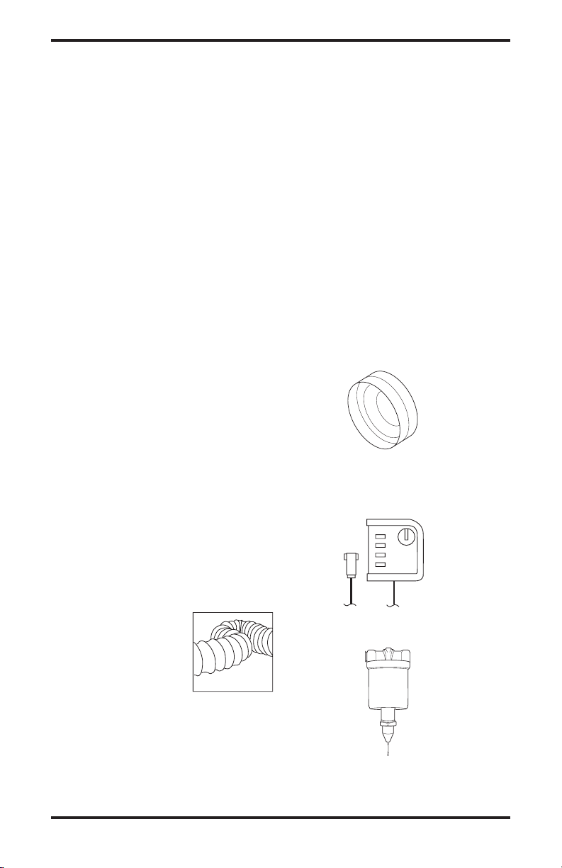
ACCESSORIES
Purchase accessories and parts from your nearest
dealer or service center. If they can not supply
these accessories or parts, either contact your
nearest parts dealer or DESA Heating Products
at 1-866-672-6040 for referral information. Parts
Centrals are listed in the Authorized Service Center
booklet supplied with heater.
FLEXIBLE VENT
HOSE
HA3220 for Model 160-IF
Model 160-IF can only con
nect one 20' section of vent
hose. Must be used wih hose
connector kit HA3230.
HA3221 for Model 280-IF
Model 280-IF can connect up to two 20' sections
of vent hose. Must be used wih hose connector
kit HA3231.
-
HOSE CONNECTOR KIT
HA3230 for Model 160-IF
HA3231 for Model 280-IF
EXTERNAL THERMOSTAT - HA3210
EXTREME COLD FUEL OIL PRE-HEATER
HA3211
-
www.desatech.com
15114909-01A

WARRANTY AND REPAIR SERVICE
KEEP THIS WARRANTY
Model No.
Serial No.
Date of Purchase
(To be filled in by purchaser)
LIMITED WARRANTY
DESA Heating Products warrants this product and any parts thereof, to be free from defects in materials and
workmanship for one (1) year from the date of first purchase when operated and maintained in accordance with
instructions. This warranty is extended only to the original retail purchaser, when proof of purchase is provided.
This warranty covers only the cost of parts and labor required to restore the product to proper operating condition.
Transportation and incidental costs associated with warranty repairs are not reimbursable under this warranty.
Warranty service is available only through authorized dealers and service centers.
This warranty does not cover defects resulting from misuse, abuse, negligence, accidents, lack of proper main
tenance, normal wear, alteration, modification, tampering, contaminated fuels, repair using improper parts or
repair by anyone other than an authorized dealer or service center. Routine maintenance is the responsibility of
the owner.
THIS EXPRESS WARRANTY IS GIVEN IN LIEU OF ANY OTHER WARRANTY EITHER EXPRESSED
OR IMPLIED, INCLUDING WARRANTIES OF MERCHANTABILITY AND FITNESS FOR A PARTICULAR
PURPOSE.
DESA Heating Products assumes no responsibility for indirect, incidental or consequential damages. Some states
do not allow the exclusion or limitation of incidental or consequential damages or limitations or exclusions may
not apply to you. This Limited Warranty gives you specific legal rights and you may also have other rights which
vary from province to province.
WARRANTY SERVICE
Should your heater require service, return it to your nearest authorized service center. Proof of purchase must be
presented with the heater. The heater will be inspected. A defect may be caused by faulty materials or workmanship.
If so, DESA Heating Products will repair or replace the heater without charge.
REPAIR SERVICE
Return the heater to your nearest authorized service center. Each Service Center is independently owned and operated.
Repairs not covered by the warranty will be billed at standard prices. We reserve the right to amend these specifications at any time without notice.
Illustrated parts lists can be obtained free of charge. Send a self-addressed stamped envelope to the address listed
below. List the heater model number and the date located in the lower right corner of this page. A service manual may
be purchased from the address listed below. Send a check for $5.00 payable to DESA Heating Products.
When writing for information regarding your heater, be sure to include the model number and serial number as shown
on the model plate.
-
Printed in USA
2701 Industrial Drive
Bowling Green, KY 42101
www.desatech.com

CALENTADOR PORTÁTIL DE AIRE FORZADO VENTILADO
MANUAL DEL PROPIETARIO
MODELOS: 160-IF, 280-IF
IMPORTANTE: Lea y comprenda este manual antes de
ensamblar, encender o dar servicio al calentador.
El uso inadecuado del calentador puede causar lesiones graves. Conserve este manual para referencias
futuras.
TABLA DE CONTENIDO
Información de seguridad .................................... 2
Desempaque ...................................................... 3
Identificación del producto ...................................
Combustibles ....................................................... 4
Para encender el calentador ............................... 4
Para apagar el calentador ................................... 4
Funcionamiento del termostato ........................... 5
Cómo mover y transportar el calentador ............. 5
Guarde este manual para referencia futura.
Para obtener más información, visite www.desatech.com
Mantenimiento preventivo ................................... 5
Solución de problemas ........................................ 5
4
Diagramas ........................................................... 7
Clasificación ilustrada de piezas .......................
Especificaciones ................................................ 15
Servicio técnico ................................................. 15
Accesorios ......................................................... 15
Garantía y servicio de reparación ..................... 16
10

INFORMACIÓN DE
SEGURIDAD
ADVERTENCIA: este producto
contiene y/o genera químicos que
el Estado de California reconoce
que causan cáncer, defectos de
nacimiento u otros daños relacionados con la reproducción.
IMPORTANTE: lea este manual
del propietario cuidadosa y completamente antes de intentar ensamblar, operar o dar servicio a
este calentador. El uso indebido
de este calentador puede causar
lesiones graves o la muerte por
quemaduras, incendio, explosiones, electrocución e intoxicación
por monóxido de carbono.
PELIGRO: ¡La intoxicación
con monóxido de carbono puede
resultar en la muerte!
Intoxicación por monóxido de carbono: las señales
tempranas de intoxicación por monóxido de carbono
se asemejan a la gripe, con dolores de cabeza, mareos y/o náuseas. Si usted presenta estos síntomas,
es posible que el calentador no esté funcionando correctamente. ¡Respire aire fresco inmediatamente!
Haga que le den servicio al calentador. El monóxido
de carbono afecta más a algunas personas que a
otras. Las más afectadas incluyen mujeres embarazadas, personas con enfermedades del corazón o de
los pulmones o anemia, aquellas bajo la influencia
del alcohol y aquellas a grandes alturas.
Asegúrese de leer y comprender todas las advertencias.
Conserve este manual para consulta. Es su guía para la
operación segura y correcta de este calentador.
1. Use solamente keroseno, diesel/aceite combustible #1 ó #2, combustibles de aviación
JET A o JP-8 para evitar el riesgo de incendio
o explosiones. Nunca utilice gasolina, nafta,
solventes para pintura, alcohol u otros combustibles altamente inflamables.
2. Carga de combustible
a) El personal encargado de la carga del com
bustible debe estar capacitado y ampliamente familiarizado con las instrucciones
del fabricante y los reglamentos aplicables
con respecto a la carga segura de combustible en las unidades de calefacción.
b)
Debe usarse solamente el tipo de combustible especificado en la placa de datos del calentador.
2
www.desatech.com
c)
Toda llama, incluyendo la del piloto, si existe, debe ser extinguida y el calentador debe
enfriarse antes de la carga de combustible.
d) Durante la carga de combustible, todas
las líneas de combustible y conexiones de
líneas de combustible deberán ser inspeccionadas para encontrar fugas. Toda fuga
debe repararse antes de poner el calentador
nuevamente en servicio.
e) En ningún momento se deberá almacenar
más que la provisión de combustible de
calentador para un día de funcionamiento
en el interior de algún edificio cercano al
calentador. La mayoría del combustible
debe almacenarse fuera del edificio.
f)
Todo almacenamiento de combustible deberá
situarse a una distancia mínima de 7,62 m (25
pies) respecto a los calentadores, sopletes,
equipo de soldadura y fuentes de ignición
similares (excepción: la reserva de combustible integrada a la unidad del calentador).
g) Siempre que sea posible, el almacenamiento
de combustible deberá restringirse a las
áreas donde las hendiduras del suelo no
permitan que el combustible gotee hacia
un incendio en una elevación menor o se
enciendan con este último.
h) El almacenamiento de combustible deberá
realizarse de acuerdo con las autoridades
que tengan jurisdicción.
3. Use solamente la tensión eléctrica y la frecuen
cia especificados en la placa del modelo.
4.
El calentador deberá estar conectado a tierra. Use
solamente un cable de extensión trialámbrico
adecuadamente conectado a tierra. Conéctelo
solamente en un enchufe con conexión a tierra.
5. Úsese solamente en áreas libres de vapores
inflamables o de alto contenido de polvo.
6.
Distancia mínima con respecto a los materiales
combustibles: 2,44 m (8 pies) de la salida de aire
caliente; 1,22 m (4 pies) de la parte superior; y
1,22 m (4 pies) de los laterales y la entrada.
7.
Sitúe el calentador en una superficie estable y nivelada mientras esté caliente o en funcionamiento, de lo contrario puede ocurrir un incendio.
8. Úsese solamente en áreas bien ventiladas.
Antes de usar el calentador, procure tener
una abertura de cuando menos 2,800 cm2 (3
pies2) para el aire fresco exterior por cada 30
kw (100,000 BTU/h) de servicio nominal.
9. Mantenga a los niños y animales alejados del
calentador en todo momento.
10. Nunca encienda el calentador cuando la cá
mara de combustión esté caliente o se haya
acumulado combustible en ella.
11. Cuando se usa con el termostato, el calentador
puede encenderse en cualquier momento.
114909-01A
-
-

INFORMACIÓN DE
SEGURIDAD
Continuación
12. Al mover o almacenar el calentador, debe
colocarse en una posición nivelada para evitar
que se derrame el combustible.
13. Use el calentador solamente de acuerdo con
las ordenanzas y códigos locales.
14. Nunca use gasolina, drenajes de cigüeñal,
nafta, solventes de pintura, alcohol u otros
combustibles altamente inflamables.
15. Nunca utilice el calentador donde estén presentes gasolina, solvente para pintura u otros
vapores inflamables.
16. Nunca utilice el calentador en áreas de estancia
o de dormir.
17. Nunca deje conectado un calentador sin la
supervisión de un adulto cuando sea posible
que haya niños o animales presentes.
18. Nunca mueva, maneje, cargue combustible o
dé servicio a un calentador en funcionamiento,
caliente o conectado.
19. Nunca fije el calentador a un tanque de com
bustible externo.
20. Los calentadores utilizados cerca de toldos,
lonas o materiales similares de protección
deben situarse a una distancia segura de dichos
materiales. La distancia mínima recomendada
para su seguridad es de 3,05 m (10 pies). Tam
bién se recomienda que dichos materiales de
protección tengan propiedades retardadoras de
fuego. Estos materiales de protección deben
estar seguramente sujetados para prevenir que
se enciendan o que afecten el funcionamiento
del calentador debido a la acción del viento.
21. Desconecte el calentador cuando no esté en uso.
22. Nunca bloquee la entrada de aire (parte pos
terior) ni la salida de aire (parte anterior) del
calentador.
DESEMPAQUE
MODELO 160-IF
1. Retire todos los materiales utilizados para
embalar el calentador para el envío.
2. Abra la caja por la parte superior.
3. Retire la conexión del conducto de humos de
la caja (consulte la figura 1).
4.
Levante y retire el material de envío de cartón.
5.
Destornille los tornillos de bloqueo de las correas
que sujetan las ruedas (consulte la figura 1).
6.
Inserte la conexión del conducto de humos al
tubo de salida de humos (consulte la figura 4).
7. Baje el calentador cuidadosamente de la
plataforma.
www.desatech.com
Tubo de salida de humos
Conexión del
conducto de
humos
Tornillos de bloqueo
Figura 1. Extracción del modelo 160-IF
de la caja
MODELO 280-IF
1. Retire todos los materiales utilizados para
embalar el calentador durante el envío.
2. Abra la caja por la parte superior.
Levante y retire el material de envío de cartón.
3.
4. Destornille los tornillos de bloqueo de la barra
de bloqueo del cubo (consulte la figura 2).
5. Saque las ruedas de la salida de aire caliente
(guardadas ahí para el envío).
-
6. Levante el calentador del extremo de la salida
de aire.
7. Inserte las ruedas en el eje.
Inserte la arandela de bloqueo (que se encuen-
8.
tra en el sobre de documentación) con el lado
convexo hacia el exterior de la máquina; usan-
-
do un martillo y una llave de ajuste de tamaño
adecuado, golpéela ligeramente para fijarla en
la posición correcta (consulte la figura 3).
9. Baje el calentador cuidadosamente de la
plataforma.
Tubo de salida
Ruedas
-
guardadas
para el envío
Conexión del
conducto de
humos
de humos
Tornillos de
bloqueo
Figura 2. Retiro del modelo 280-IF de la
caja
Arandela de
bloqueo
Eje
Rueda
Figura 3. Ensamblaje de ruedas/eje para
el modelo 280-IF
3114909-01A

IDENTIFICACIÓN DEL
Salida
de aire
caliente
Cubierta
inferior
Figura 4. Calentador portátil de aire
PRODUCTO
Conexión del conducto de humos
Cubierta
superior
Panel de
control
Cable de
alimentación
forzado ventilado
Resguardo
del ventilador
Tapa del
tanque de
combustible
COMBUSTIBLES
ADVERTENCIA: use solamente keroseno, diesel/aceite
combustible #1 ó #2, combustible de aviación JET A o JP-8
para evitar riesgos de incendio
o explosión. Nunca utilice gasolina, aceite drenado de cárteres,
nafta, solventes de pintura,
alcohol u otros combustibles
altamente inflamables.
Use solamente keroseno, diesel/aceite combustible #1 ó #2, combustible de aviación JET A o
JP-8. También se pueden usar combustibles más
pesados, como el aceite combustible nº 2 o el
combustible diesel nº 2, pero ocasionarán:
• Olor evidente
•
Mantenimiento adicional del filtro de combustible
• La necesidad de aditivos no tóxicos, anticongelantes en climas muy fríos
No use combustibles más pesados que el grado nº 2 ni
aceites pesados, como el aceite que se drena de los cárteres del cigüeñal. Estos aceites pesados no se encenderán
adecuadamente y contaminarán el calentador.
IMPORTANTE: use un recipiente de almacenamiento para KEROSENO SOLAMENTE (azul) o para
DIESEL SOLAMENTE (amarillo). Asegúrese de que
el recipiente de almacenamiento esté limpio. Substancias extrañas como óxido, polvo o agua ocasionarán
que el ensamblaje del control de encendido apague el
calentador. Las substancias extrañas pueden también
requerir que el sistema de combustible del calentador
tenga que limpiarse frecuentemente.
PARA ENCENDER EL
CALENTADOR
IMPORTANTE: revise y comprenda
las advertencias que aparecen en la
sección Información de seguridad,
en la página 2. Son necesarias para
hacer funcionar este calentador
de manera segura. Siga todas las
ordenanzas y códigos locales al
utilizar este calentador.
1. Llene el tanque con combustible (consulte la
sección Combustibles).
2. Conecte el cable de alimentación del calen
tador a un enchufe de 3 puntas o un cable de
extensión aprobados, con conexión a tierra y
de 120 V/60 Hz.
Requisitos de medida del cable de extensión
De 1,8 a 3 m (6 a 10 pies) de longitud, use un
cable de clasificación 18 AWG (0,75 mm2)
De 3,3 a 30,5 m (11 a 100 pies) de longitud, use
un cable de clasificación 16 AWG (1,0 mm2)
De 30,8 a 61 m (101 a 200 pies) de longitud, use
un cable de clasificación 14 AWG (1,5 mm2)
3. Si hay un termostato conectado, colóquelo en
la temperatura máxima.
4.
Mueva el interruptor (3 en la figura Panel de control
eléctrico, página 7) a la posición con el símbolo:
; el ventilador deberá iniciarse y el calentador deberá encenderse luego de varios
segundos.
La primera vez que se usa el calentador, o luego de que el circuito de combustible haya sido
completamente drenado, es posible que el flujo
de combustible a la boquilla sea insuficiente y
es posible que se active el control de llama, el
cual apagará el calentador; si esto sucede, espere
aproximadamente un minuto y luego presione el
botón de restablecimiento (1 en la figura Panel
de control eléctrico, página 7) para encender el
calentador nuevamente.
PARA APAGAR EL
CALENTADOR
1. Mueva el interruptor (3 en el Panel de control
eléctrico, página 7) a la posición "O" ajuste el
mecanismo de control, por ejemplo, colocando
el termostato en una posición más baja. La
llama se apagará y el ventilador continuará
funcionando hasta que la cámara de combustión se haya enfriado completamente.
2. Espere a que el ventilador se detenga antes
de desenchufar el calentador. Desconecte el
calentador cuando no esté en uso.
-
4
www.desatech.com
114909-01A

FUNCIONAMIENTO DEL
TERMOSTATO
El calentador solamente puede funcionar de manera
automática cuando hay un termostato conectado a él
fijando el cable a las terminales 2 y 3 del enchufe (4
en la figura Panel de control eléctrico
, página 7).
CÓMO MOVER Y
TRANSPORTAR EL
CALENTADOR
ADVERTENCIA: antes de mover el calentador debe apagarlo
(consulte Para apagar el calenta-
dor), desconectar el enchufe de la
fuente de alimentación y esperar
a que el calentador se enfríe.
Antes de levantar o mover el calentador, asegúrese
de que la tapa del tanque de combustible esté
colocada firmemente en su lugar.
El calentador puede ofrecerse en una versión
portátil, con ruedas, o en una versión suspendida,
montado sobre una estructura de soporte y coloca
do en su lugar con cables o cadenas. En el primer
caso, para mover el calentador, sencillamente coja
la manija de soporte y mueva el calentador. En el
segundo caso, el calentador debe ser levantado con
un vehículo elevador o algún aparato similar.
MANTENIMIENTO
PREVENTIVO
Para asegurar que el calentador continúe funcionando correctamente, es necesario limpiar la
cámara de combustión, el quemador y el ventilador
de manera periódica.
ADVERTENCIA: se deben
realizar los siguientes pasos antes de dar servicio al calentador:
apagar el calentador, siguiendo las
instrucciones de la sección anterior; desconectar el enchufe de la
fuente de alimentación y esperar a
que el calentador se enfríe.
Cada 50 horas de uso, es necesario:
• Desarmar el cartucho del filtro, sacarlo y lim
piarlo con combustible limpio.
• Retirar la cubierta exterior cilíndrica y limpiar
el interior y las aspas del ventilador.
• Revisar la condición de los cables y de las
conexiones de alto voltaje en los electrodos.
-
• Desarmar el quemador, limpiar las piezas, y
luego limpiar los electrodos y ajustarlos, si es
necesario, a la distancia indicada en Distancias
entre electrodos
en la página 7.
-
SOLUCIÓN DE PROBLEMAS
FALLA OBSERVADA
El ventilador no arranca y la
llama no se enciende
POSIBLE CAUSA
1. No hay corriente eléctrica.
2. Configuración incorrecta del
termostato (si está incluido).
3. Termostato defectuoso.
4. El devanado del motor está
quemado o dañado.
5. Los rodamientos del motor se
han atascado.
6. El condensador del motor se ha
quemado.
7. El enchufe del termostato no
está conectado.
www.desatech.com
SOLUCIÓN
1 A) Verifique las características
del sistema eléctrico (120 V
- 60 Hz).
B) Verifique que el interruptor
funcione y que esté en la posi
ción correcta.
C) Verifique que el fusible no
se haya quemado.
2.
Verifique que la configuración del
termostato sea correcta (por ejem
plo, el valor de temperatura en el
termostato debe ser mayor que la
temperatura del ambiente).
3. Reemplace el termostato.
4. Reemplace el motor.
5. Reemplace los rodamientos.
6. Reemplace el condensador.
7.
Conecte el enchufe del
termostato.
-
-
5114909-01A

SOLUCIÓN DE PROBLEMAS
FALLA OBSERVADA
El ventilador arranca pero la
llama no se enciende o no se
mantiene encendida.
El ventilador se inicia y la llama se enciende, pero produce
humo.
El calentador no se apaga.
El ventilador no se apaga.
Continuación
POSIBLE CAUSA
1. El encendedor no está funcionando.
2. Control de llama defectuoso.
3. La célula fotoelécrica no está
funcionando.
4. El combustible no está llegando
al quemador o no está llegando
una cantidad suficiente.
5. La válvula de solenoide no
funciona.
1. Aire insuficiente para la combustión.
2.
Demasiado aire para la combustión
3. El combustible está sucio o
4. Se ha infiltrado aire al circuito
5. Cantidad inadecuada de com-
6. Demasiado combustible en el
1. Termostato de ventilador defec-
.
contiene agua.
de combustible.
bustible en el quemador.
quemador.
tuoso.
SOLUCIÓN
1. A) Revise las conexiones de
los cables de encendido a los
electrodos y transformador.
B) Revise la posic ión de
los electrodos y la distancia
entre ellos, de acuerdo con el
diagrama en la página 7.
C) Verifique que los electrodos
estén limpios.
D) Reemplace el transforma-
dor de encendido.
2.
Reemplace el control de llama.
3. Limpie o reemplace la célula
fotoeléctrica.
4.
A) Verifique que la conexión entre
la bomba y el motor esté intacta.
B)Verifique que no se haya
infiltrado aire en el circuito de
combustible, revise los tubos
y junta del filtro.
C) Limpie o, si es necesario,
reemplace la boquilla.
5.
A) Revise la conexión eléctrica.
B) Revise el termostato de
seguridad (LI).
C) Limpie o, si es necesario, reemplace la válvula de solenoide.
1.
A)Retire cualquier objeto que
bloquee u obstruya los ductos
de aspiración y/o flujo de aire.
B) Revise la posición del
anillo de regulación de aire.
C) Limpie el disco del quemador.
2. Revise la posición del anillo
de regulación de aire.
3. A) Reemplace el combustible
con combustible limpio.
B) Limpie el filtro de combus-
tible.
4. Revise la condición de los
tubos y de la junta del filtro
de combustible.
5.
A) Revise la presión de la
bomba.
B) Limpie o reemplace la
boquilla.
6.
A) Revise la presión de la
bomba.
B) Reemplace la boquilla.
1. Reemplace la válvula de solenoide.
1. Reemplace el termostato del
ventilador (FA).
6
www.desatech.com
114909-01A

DIAGRAMAS
1 2 3 6 8 9
12
13
11
4
5 7
10
0.08" - 0.12"
(2-3 mm)
!
C
A
UT
IO
N
:
H
o
t
w
h
i
le
i
n
o
pe
rati
o
n
.
D
o
n
o
t
to
u
c
h.
Ke
e
p
c
h
il
d
ren,
a
n
im
a
ls
,
c
lo
th
in
g
a
n
d
c
o
m
b
us
t
i
bl
e
s
aw
a
y.
!
P
R
E
CA
UC
I
Ó
N:
C
al
ie
n
te
cu
a
nd
o
e
s
t
á
en
o
p
e
r
ac
ió
n
.
No
t
ocar
.
M
a
n
te
n
g
a
a lo
s
n
iñ
o
s
,
a
ni
m
a
l
e
s
,
v
e
s
t
im
e
nt
a
y
c
om
b
u
s
ti
b
l
es
a
le
-
j
ad
o
s.
!
AT
T
E
N
T
IO
N
:
L’
ap
pa
re
i
l
de
c
hauffage
e
s
t
b
rû
la
n
t
p
en
d
a
n
t
l
e
fo
n
c
t
i
o
n
ne
m
e
nt.
N
e
le
to
u
c
he
z
p
a
s
.
T
e
n
e
z
l
es
e
n
fa
n
ts
, les
a
nim
a
u
x
e
t
l
es
vê
t
e
m
e
n
t
s
à
l’
é
c
ar
t
d
e
c
e
t
ap
p
a
re
il
.
O
P
E
R
A
T
IN
G
I
N
S
T
R
U
C
T
IO
N
S
ST
A
RT
1
.
Fill
t
a
nk
U
se
o
nl
y
ke
ro
se
n
e
,
#
1
&
#
2
d
ie
se
l
a
n
d
f
u
el
o
il
,
JE
T
A
o
r
JP
8
f
ue
l
s.
2
.
P
lu
g
p
ow
e
r
cord
i
n
to
12
0V
/6
0
Hz
outl
et
.
Po
w
e
r
in
d
icator
lig
h
t
sh
o
ul
d
be
on
.
3
.
If
e
q
u
ip
pe
d
, ad
j
us
t th
e
r
m
o
s
ta
t
k
no
b
to
t
he wa
rm
es
t
sett
i
ng
.
4
.
P
u
s
h
ON
/
OF
F
sw
itch
t
o
O
N
( )
.
F
a
n
m
o
to
r
sh
ou
ld
s
t
ar
t
i
mm
e
d
ia
t
e
ly
.
He
a
te
r
wi
l
l
i
gn
i
te
wi
th
i
n
1
0
s
econds
.
5
.
If
eq
ui
p
pe
d,
ad
j
u
s
t
th
e
rm
osta
t to desired
s
etti
n
g
.
ST
OP
Pu
s
h
O
N
/
O
F
F
sw
it
c
h
to
OF
F
(
O).
F
a
n
m
o
to
r
wi
l
l
cont
i
n
u
e
to
r
u
n.
Do
n
o
t
un
plug he
a
te
r
u
n
t
i
l
c
o
o
l
in
g
c
y
cl
e
i
s
c
o
mp
l
e
te.
S
e
e
m
o
d
e
l
d
e
c
a
l
o
r
o
w
n
er
’s
m
a
n
u
a
l
f
or
a
d
d
i
t
io
n
a
l
o
p
e
r
a
t
i
n
g
i
n
s
t
r
u
c
-
t
io
n
s
,
s
a
fe
t
y
r
e
q
u
i
r
e
m
e
n
t
s
,
a
n
d
s
p
e
c
i
fi
c
a
t
i
o
n
s
.
O
PE
R
A
T
I
N
G
I
N
S
T
R
U
C
T
I
O
N
S
ST
A
R
T
1
.
Fill
t
a
n
k
U
se
o
nl
y
ker
os
e
n
e
,
#
1
&
#
2
d
ie
s
el
a
n
d
f
u
e
l
o
i
l
,
JE
T
A
o
r
JP
8
f
u
e
l
s.
2
.
P
lu
g
p
o
we
r
co
r
d
in
t
o
1
2
0V
/
6
0
H
z
o
u
t
le
t.
P
ow
er
i
n
d
icator
ligh
t
should
be
on
.
3
.
If
e
q
u
ip
pe
d
, adju
s
t
t
he
r
m
os
ta
t kn
o
b
to
t
he
warmes
t
se
t
t
i
n
g
.
4
.
P
u
sh
ON
/OFF
sw
it
ch
t
o
ON
(
)
. Fa
n
mo
t
or
s
h
o
u
ld
st
a
r
t
i
mm
e
di
-
a
tely
. He
a
te
r
wi
l
l
i
gn
i
te
wi
th
i
n
1
0
se
co
n
ds
.
5
.
If
eq
ui
p
pe
d, ad
j
us
t
ther
m
o
st
at
to desir
e
d sett
i
ng
.
ST
OP
Pu
s
h
O
N
/
O
F
F
s
w
i
t
c
h
to OF
F
(
O
)
.
F
an
mo
t
or
wi
l
l
co
n
ti
n
u
e
to
r
u
n.
Do
n
o
t
u
n
plug
h
e
a
te
r
u
nt
i
l co
o
l
in
g
c
y
cl
e
i
s
c
om
p
l
e
te
.
Se
e
mo
d
el
d
e
c
a
l
or
o
w
n
er
’
s
m
a
n
u
a
l
f
or
a
d
d
it
i
o
n
a
l
o
p
er
at
i
n
g
in
st
r
u
c
-
t
io
n
s
,
s
a
fe
t
y
r
e
q
u
i
r
e
m
e
n
t
s
,
an
d
s
p
e
c
i
fi
c
a
t
i
o
n
s
.
O
PE
R
A
T
I
N
G
IN
S
TR
U
C
T
IO
NS
ST
A
RT
1.
Fi
l
l
t
a
n
k
Us
e
o
nl
y
ke
r
ose
ne
,
#
1
&
#
2
d
iese
l
a
n
d
f
u
el
o
il
,
JET
A
o
r
JP-8
f
u
e
ls
.
2.
P
lu
g
p
ow
e
r
co
rd
in
t
o
1
2
0
V
/
6
0
Hz
o
u
t
le
t
.
Po
w
e
r
i
n
d
i
ca
to
r
li
gh
t
s
h
ou
l
d
be
o
n.
3.
If
eq
ui
p
pe
d
,
a
d
ju
s
t
the
rm
os
t
at
k
n
ob
to the
wa
r
m
es
t
sett
i
ng
.
4
.
P
us
h
ON
/
OF
F
sw
it
ch
t
o
ON ( )
.
F
an
mo
t
or
should
st
a
r
t
i
mm
e
d
i
-
ate
l
y
. He
at
e
r
wi
l
l
i
g
n
i
te
wi
t
hi
n
1
0
s
econ
d
s
.
5
.
I
f
e
q
u
i
p
pe
d,
ad
j
us
t
t
he
r
m
os
tat
t
o
d
esired
s
e
tt
i
n
g
.
S
T
OP
Pu
s
h
ON/O
F
F
swit
c
h
to
OFF
(
O
).
F
a
n
moto
r
wi
l
l
c
o
n
t
in
u
e
t
o
r
u
n.
Do
no
t
u
np
l
u
g
he
at
e
r
un
ti
l
c
o
ol
i
n
g
cy
c
le
is
c
o
mp
l
e
t
e
.
S
e
e
m
o
d
e
l
d
e
c
a
l
or
o
w
ne
r
’
s
m
a
n
u
a
l
f
or
a
d
d
it
io
n
a
l
o
pe
r
a
t
i
ng
i
n
s
t
r
u
c
-
t
i
o
n
s
,
s
a
fe
ty
r
e
qu
i
r
e
m
e
n
t
s,
a
n
d
s
pe
c
i
fic
a
t
i
o
n
s
.
2
7
0
0
1
I
n
d
us
t
ri
a
l
D
ri
v
e
P.
O
.
B
o
x
9
00
4
Bo
wl
i
n
g
G
r
e
en
,
K
y
4
2
1
0
2
w
ww
.
d
e
s
at
e
c
h
.
co
m
1
13
3
44
-0
8
U
N
PL
U
G
HE
A
T
E
R
B
E
F
O
R
E
R
E
M
O
V
I
NG
CO
VE
R
U
N
P
LU
G
HE
A
T
E
R
B
E
F
O
RE
R
E
M
O
V
I
N
G
CO
V
ER
U
N
P
L
U
G
HE
A
T
E
R
B
E
F
O
R
E
RE
M
OV
I
N
G
C
OV
E
R
Ma
de
i
n
I
t
a
l
y
FLA
M
E
C
O
N
TRO
L
R
E
S
E
T
F
LA
M
E
CO
N
TR
O
L
R
E
S
E
T
FLA
M
E
C
O
N
T
RO
L
R
E
S
E
T
M
a
n
uf
ac
t
u
re
d
f
o
r
:
DIAGRAMA DE FUNCIONAMIENTO DEL CALENTADOR
1. Cámara de combustión
2. Conexión de protección contra
viento del conducto de humos
3. Quemador
4. Boquilla
5. Circuito de combustible
6. Bomba de combustible
7.
Válvula de combustible eléctrica
8. Motor
9. Ventilador
10.
Soporte de devanado de cables
11. Filtro de combustible
12. Tanque de combustible
13. Panel de control
PANEL DE CONTROL ELÉCTRICO
1. Botón de restablecimiento
2. Etiqueta de funcionamiento
6
1
2
4
3. Interruptor principal
4. Conector para el termostato
ambiental
5. Cable de alimentación
6. Indicador de alimentación
7. Enchufe del termostato (debe
mantenerse fijo si no se utiliza
algún dispositivo de control)
7
3
5
DIAGRAMA DE CONEXIONES DEL
CONDUCTO DE HUMOS
Tubo de
6 pulgadas
de diámetro
Conector del
conducto de
humos
www.desatech.com
DISTANCIAS ENTRE ELECTRODOS
2-3 mm
(0,08 - 0.12 pulgadas)
7114909-01A

DIAGRAMAS
5
4
A
3
2
D
C
1
B
A
6
2
D
C
1
B
5
E
Continuación
DIAGRAMA DE COLOCACIÓN DEL TUBO DE SALIDA DE LOS GASES
ADVERTENCIA: los diagramas son típicos; la instalación del con-
ducto de humos debe cumplir con las normas legales vigentes.
A. Mínimo de 3 pies
B. Mínimo de 3 pies
C. Tan corto como sea posible
D. Igual o mayor al diámetro de la salida de
humos del quemador
E. Mínimo de 3 pies
1. Dispositivo de protección contra el viento
conectado al calentador
2. Pieza cruzada horizontal con un ángulo míni
mo hacia arriba de al menos 5°, un mínimo de
2,54 cm (1 pulgada) por cada 30,48 cm (12
pulgadas) de desplazamiento horizontal
3.
Conducto de humos con dimensiones internas mínimas de 8 pulgadas x 8 pulgadas
4. Ventanilla antiexplosiones y para inspecciones del conducto de humos.
5. Pared de protección externa
6. Activador de extracción en forma de H
-
8
www.desatech.com
114909-01A

DIAGRAMAS
A
Continuación
DIAGRAMA DEL CABLEADO ELÉCTRICO
FU Fusible
6A 160-IF
10A 280-IF
IT Transformador de alto voltaje
LI Termostato de seguridad
EV Válvula de solenoide
FO Fotocélula
FA Termostato de ventilador
CO Condensador
MV Motor de ventilador
Luz de alimentación
ST
IN Interruptor
TA Toma para el termostato ambiental
RE Relé
AP
Caja de control
REGULACIÓN DEL AJUSTE DEL CONTROLADOR DE AIRE DE
COMBUSTIÓN
Controlador de aire
160-IF A= 15 mm (19/32 de pulgada)
280-IF A= 8 mm (5/16 de pulgada)
www.desatech.com
9114909-01A

CLASIFICACIÓN ILUSTRADA DE PIEZAS
1
2
33
3
4
8
11
12
13
14
15
16
17
18
19
20
21
22
23
24
25
35
30
34
26
27
28
29
30
31
36
7
6
28
10
9
28
5
32
MODELOS: 160-IF, 280-IF
10
www.desatech.com
114909-01A

Esta lista contiene las piezas reemplazables utilizadas en el calentador. Al ordenar las partes, asegúrese
LISTA DE PIEZAS
de proporcionar el número de modelo y número de serie correctos (de la placa del modelo), después el
número de parte y descripción de la parte deseada.
CLAVE NÚMERO DE PIEZA
NO. 160-IF 280-IF DESCRIPCIÓN CANT.
1 115130-01 115130-02 Manija posterior 1
2 115131-01 115131-02 Soporte del marco 1
3 115132-01 115132-02 Cono de la salida 1
4 115133-01 115133-01 Tapón del extremo 2
5 115134-01 115134-02 Eje 1
6 115135-01 115135-02 Rueda 2
7 115136-01 115136-02 Arandela de bloqueo de la rueda 2
8 115137-01 115138-01 Tanque de combustible 1
9 115139-01 115139-01 Tapón de drenado 1
10 115140-01 115140-01 Junta tórica del tapón de drenado 1
11 115141-01 115141-01 Tapón del combustible 1
12 115142-01 115142-02 Resguardo del ventilador 1
13 115143-01 115144-01 Ventilador 1
14 115145-01 115145-01 Tornillo fijo del ventilador 1
15 115146-01 115147-01 Soporte del motor 1
16 115148-01 115148-02 Desviador de aire 3
17 115149-01 115150-01 Cámara de combustión 1
18 115151-01 115152-01 Protector de resguardo de la llama 1
19 115153-01 115154-01 Soporte de cubierta, derecha 1
20 115155-01 115156-01 Soporte de cubierta, izquierda 1
21 115157-01 115158-01 Cubierta inferior 1
22 115159-01 115160-01 Cubierta superior 1
23 115161-01 115162-01 Cubierta superior, cobertura posterior 1
24 115163-01 115163-01 Conector del conducto de humos 1
25 115164-01 115164-01 Buje de cable 1
26 115165-01 115165-01 Tornillo, M5 x 16 4
27 115166-01 115166-01 Tornillo, 10 x 1/2 pulgada 6
28 115248-01 115248-01 Tuerca, M6 10
29 115249-01 115249-01 Tornillo de casquillo 6
30 115250-01 115250-01 Tornillo, M6 x 16 4
31 115251-01 115251-01 Tornillo, 14 x 1/2 pulgada 4
32 115167-01 115167-01 Tuerca de clip 6
33 115168-01 115168-01 Tornillo, M6 x 30 4
34 115169-01 115169-01 Gancho para el cable de alimentación 2
35 ----- 115170-01 Barra de soporte de la manija 2
36 115171-01 115171-02 Tapón de rueda amarillo 2
114909-01A
www.desatech.com
11

1
2
3
4
5
6
7
8
9
10
11
12
13
14-1
14-2
14-3
14-4
15
16
17
18
19
20
CLASIFICACIÓN ILUSTRADA DE PIEZAS Y LISTA DE PIEZAS
CAJA DE CONTROL PARA LOS MODELOS 160-IF, 280-IF
CLAVE NÚMERO DE PIEZA
NO. 160-IF 280-IF DESCRIPCIÓN CANT.
1 115172-01 115172-01 Soporte de la caja de control 1
2 Base de la caja de control 1
3 115173-01 115173-01 Caja de control 1
4 115174-01 115174-01 Transformador de 120 V 1
5 115175-01 115175-02 Cable de alta tensión 2
6 115176-01 115176-01 Relé 1
7 115177-01 115177-01 Placa de terminales 1
8 115178-01 115178-01 Cubierta de componentes eléctricos 1
9 115179-01 115179-01 Luz de alimentación 1
10 115180-01 115180-01 Cubierta del interruptor 1
11 115181-01 115181-01 Interruptor 1
12 115182-01 115182-01 Conector de 4 patas 1
13 115183-01 115183-01 Enchufe 1
14 115184-01 115184-01 Cable eléctrico con enchufe y
Asegurador de cable 1
14-1 115185-01 115185-01 Asegurador de cable 1
14-2 115186-01 115186-02 Fusible 1
14-3 115187-01 115187-01 Cable eléctrico con enchufe 1
14-4 115188-01 115188-01 Tornillo 8 x 3/8 de pulgada 2
15 115189-01 115189-01 Tornillo 8 x 1
16 115190-01 115190-01 Tornillo 4 x 1/2 pulgada 2
17 115191-01 115191-01 Tuerca con anclaje M6 2
18 115250-01 115250-01 Tornillo M6 x 16 mm 2
19 115192-01 115192-01 Tornillo, 4 x 3/8 de pulgada 2
12
www.desatech.com
1
/2 pulgada 2
114909-01A

CLASIFICACIÓN ILUSTRADA DE PIEZAS Y LISTA DE PIEZAS
1
1
2
3
4
5
6
7
8
11
11
9
10-1
10-2
10-3
10-4
10-5
ENSAMBLAJE DEL FILTRO DE COMBUSTIBLE PARA LOS
MODELOS 160-IF, 280-IF
CLAVE NÚMERO DE PIEZA
NO. 160-IF 280-IF DESCRIPCIÓN CANT.
1 115252-01 115252-01 Tubo de combustible flexible 1
2 115253-01 115253-01 Buje de cable 1
3 115193-01 115193-02 Tubo de levantamiento de combustible 1
4 115194-01 115194-01 Conexión recta de 1/4 de pulgada 1
5 115195-01 115195-01 Tuerca 3/8 de pulgada x 5 1
6 115196-01 115196-01 Soporte de base del filtro 1
7 115197-01 115197-01 Conector macho doble 1
8 115198-01 115198-01 Codo de 90˚ 1
9 115199-01 115199-01 Conector recto 1
10 115200-01 115200-01 Ensamblaje del filtro 1
10-1 115201-01 115201-01 Junta tórica del filtro 1
10-2 115202-01 115202-01 Junta superior del filtro de combustible 1
10-3 115203-01 115203-01 Filtro 1
10-4 115204-01 115204-01 Caja del filtro 1
10-5 115205-01 115205-01 Junta inferior del filtro de aceite 1
11 115206-01 115206-01 Conector recto de 1/8 de pulgada 2
www.desatech.com
13114909-01A

CLASIFICACIÓN ILUSTRADA DE PIEZAS Y LISTA DE PIEZAS
2
1
3
4
5
6
7-1
7-2
14
9
8
12
11
1516
26
17
18
29
25
25
30
19
20
10
11
12
27
13
21
24
28
23
22
Blue Mark
MOTOR, BOMBA DE COMBUSTIBLE Y COMPONENTES DE QUEMADOR
PARA LOS MODELOS 160-IF, 280-IF
(punto azul)
CLAVE NÚMERO DE PIEZA
NO. 160-IF 280-IF DESCRIPCIÓN CANT.
1 115207-01 115207-02 Cable del electrodo 2
2 115208-01 115208-01 Termostato de enfriamiento (ventilador) 1
3 115209-01 115209-01 Termostato de sobrecalentamiento (punto azul) 1
4 115210-01 115210-01 Electrodo de cerámica 2
5 115211-01 115211-01 Conector de cable (90˚) 2
6 115212-01 115212-01 Línea de combustible 1
7 115213-01 115213-01 Bomba de alta presión 1
7-1 115214-01 115214-01 Válvula de solenoide 1
7-2 115215-01 115215-01 Estructura y caja de la bomba 1
8 115216-01 115216-01 Conector de 1/4 de pulgada 2
9 115217-01 115217-02 Acoplador, motor y bomba 1
10 115218-01 115218-01 Conector de 90˚ de 1/8 de pulgada 1
11 115219-01 115219-01 Casquillo de 4 mm 2
12 115220-01 115220-01 Tuerca del casquillo 2
13 115221-01 115222-01 Motor 1
14 115223-01 115223-01 Niple de la línea de combustible 1
15 115224-01 115224-01 Conector de 1/8 de pulgada 1
16 115225-01 115225-01 Tuerca, M14 1
17 115226-01 115226-01 Pestaña del quemador 1
18 115227-01 115227-01 Soporte de la boquilla 1
19 115228-01 115228-01 Difusor 1
20 115229-01 115229-02 Boquilla, 80° 1
21 115230-01 115230-01 Cinturón de regulación de aire 1
22 115231-01 115231-01 Fotocélula 1
23 115232-01 115232-01 Abrazadera de la fotocélula 1
24 115233-01 115233-01 Pestaña de fotocélula 1
25 115234-01 115234-01 Tornillo, 8 x 3/8 de pulgada 3
26 115235-01 115235-01 Tuerca, M5 1
27 115236-01 115236-01 Tornillo Allen 1
28 115237-01 115237-01 Tornillo 6 x 1/2 pulgada 1
29 115238-01 115238-01 Tornillo M4 x 8 mm, Allen 1
30 115239-01 115239-01 Tornillo M6 x 25 mm, Allen 1
14
www.desatech.com
114909-01A

ESPECIFICACIONES
Tamaño del modelo 160-IF 280-IF
Potencia nominal de salida máxima (BTU/h) 158,000 278,000
Potencia nominal de salida neta (BTU/h) 133,000 234,400
Combustible Use solamente keroseno, diesel/aceite combustible
#1 ó #2, combustible de aviación JET A o JP-8*.
Capacidad del tanque de combustible
(Galones EE.UU./Litros) 17/65 28/105
Consumo de combustible
(Galones por h/litros por h) 1.27/4.81 2.22/8.40
Presión de bomba (PSI) 145 174
Requerimientos de electricidad 120 V/60 Hz (el mismo para ambos modelos)
Amperaje (operación normal) 4.8 8.5
RPM del motor 2850 3490
Salida de aire caliente (CFM) 1,060 1,940
Peso con embalaje 190/86 320/145
(lb/kg aproximados)
Peso del calentador sin combustible 161/74 273/124
(lb/kg aproximados)
* El uso de diesel/aceite combustible #2 resultará en olor perceptible y puede requerir mantenimiento
adicional del filtro de combustible. El uso en temperaturas de frío extremo puede requerir aditivos
anticongelantes no tóxicos.
SERVICIO TÉCNICO
Es posible que tenga preguntas adicionales acerca
de la instalación, el funcionamiento o la solución
de problemas. Si es así, póngase en contacto con el
departamento de servicio técnico de DESA Heating
Products al 1-866-672-6040. Cuando llame tenga a la
mano el número de modelo y de serie de su calentador.
También puede visitar el sitio web de servicios técnicos
de DESA Heating Products en www.desatech.com.
ACCESORIOS
Adquiera accesorios y partes mediante su distribuidor
o centro de servicio más cercano. Si no pueden proporcionarle dichos accesorios y partes, comuníquese con su
distribuidor de partes más cercano o con DESA Heating
Products al 1-866-672-6040 para obtener información
de referencia. Las centrales de partes están en la lista en
el libro de Centro de servicio autorizado proporcionado
con el calentador.
MANGUERA FLEXIBLE DE LA VENTILA
HA3220 para el modelo 160-IF
El modelo 160-IF sólo puede
conectar una sección de manguera
de ventilador de 6,1 metros (20
pies). Debe usarse con el juego
conectores de manguera HA3230
HA3221 para el modelo 280-IF
El modelo 280-IF puede conectar hasta dos secciones de
manguera de ventilador de 6,1 metros (20 pies). Debe
usarse con el juego conectores de manguera HA3231
www.desatech.com
JUEGO DE CONECTORES DE
MANGUERA
HA3230 para el modelo 160-IF
HA3231 para el modelo 280-IF
TERMOSTATO EXTERNO HA3210
PRECALENTADOR DE ACEITE
Y COMBUSTIBLE PARA FRÍO
EXTREMO HA3211
15114909-01A

GARANTÍA Y SERVICIO DE REPARACIÓN
GUARDE ESTA GARANTÍA
N° de modelo
N° de serie
Fecha de compra
(Para ser llenado por el comprador)
GARANTÍA LIMITADA
DESA Heating Products (productos de calefacción de DESA) garantiza que este producto y todas sus piezas están
libres de defectos en los materiales y la mano de obra durante un (1) año a partir de la primera compra, siempre
que se hayan operado y mantenido de acuerdo con las instrucciones. Esta garantía es válida solamente para el
comprador minorista original, si se proporciona el comprobante de compra.
Esta garantía cubre exclusivamente el costo de las piezas y mano de obra que se necesiten para hacer que su
producto funcione adecuadamente de nuevo. La transportación y costos incidentales asociados con reparaciones
garantizadas no son reembolsables bajo esta garantía.
El servicio de garantía está disponible sólo a través de distribuidores autorizados y centros de servicio.
Esta garantía no cubre defectos ocasionados por mal uso, abuso, negligencia, accidentes, falta de mantenimiento
adecuado, desgaste normal, alteración, modificación, manipulación, combustibles contaminados, reparación
usando piezas inadecuadas o reparación realizada por cualquiera que no sea un distribuidor o centro de servicio
autorizado. El mantenimiento de rutina es responsabilidad del propietario.
ESTA GARANTÍA EXPRESA SUSTITUYE A CUALQUIER OTRA GARANTÍA, YA SEA EXPRESA O IM
PLÍCITA, INCLUSO LAS GARANTÍAS DE COMERCIABILIDAD E IDONEIDAD PARA UN PROPÓSITO
EN PARTICULAR.
DESA Heating Products no asume responsabilidad por daños consecuentes, indirectos o fortuitos. Algunos estados
no permiten la exclusión o limitación de daños incidentales o perjuicios, o es posible que las exclusiones no sean
aplicables a usted. Esta garantía limitada le otorga derechos legales específicos y usted podría tener también otros
derechos que varían de una provincia a otra.
-
SERVICIO DE GARANTÍA
Si su calentador requiere servicio, regréselo al centro de servicio autorizado más cercano. Se debe presentar una prueba
de compra con el calentador. El calentador será inspeccionado. Un defecto puede ser ocasionado por materiales o mano
de obra defectuosos. Si es así, DESA Heating Products reparará o reemplazará el calentador sin ningún cargo.
SERVICIO DE REPARACIÓN
Devuelva el calentador al centro de servicio autorizado más cercano. Cada Centro de servicio tiene un propietario y
una operación independiente. Las reparaciones no cubiertas por la garantía se cobrarán a los precios regulares. Nos
reservamos el derecho de modificar estas especificaciones en cualquier momento sin aviso previo.
Las listas ilustradas de partes pueden obtenerse gratis. Envíe un sobre con su nombre, dirección y sellos postales a
la dirección que se presenta a continuación. Escriba el número de modelo del calentador y la fecha situados en la
esquina inferior derecha de esta página. El manual de servicio puede adquirirse en la dirección que se encuentra a
continuación. Envíe un cheque por $5,00 dólares a nombre de DESA Heating Products.
Cuando escriba solicitando información sobre su calentador, asegúrese de incluir el número de modelo y el número
de serie como se muestran en la placa modelo.
2701 Industrial Drive
Bowling Green, KY 42101
www.desatech.com
Impreso en los EE.UU.

APPAREIL DE CHAUFFAGE À AIR FORCÉ PORTABLE À
CONDUIT D’ÉVACUATION
MANUEL D’UTILISATION
MODÈLES: 160-IF, 280-IF
IMPORTANT : lisez et comprenez ce manuel avant d’assembler, d’allumer ou de réparer l’appareil de chauffage.
Une mauvaise utilisation de l’appareil de chauffage peut
causer des blessures graves. Conservez ce manuel
pour référence future.
TABLE DES MATIÈRES
Information relative à la sécurité ......................... 2
Déballage ........................................................... 3
Identification du produit .......................................
Combustibles ....................................................... 4
Pour allumer l’appareil de chauffage ...................
Pour arrêter l’appareil de chauffage .................... 4
Utilisation du thermostat ...................................... 5
Déplacement et transport de l’appareil
de chauffage ....................................................
Conservez ce mode d’emploi pour consultation future.
Pour plus de détails, visitez le site www.desatech.com
Entretien préventif ............................................... 5
Dépannage .......................................................... 5
4
Schémas ............................................................. 7
Vue détaillée des pièces ....................................
Spécifications ....................................................
4
Service technique .............................................. 15
Accessoires ....................................................... 15
Service de garantie et de réparation ......Couverture arrière
5
10
15

INFORMATION RELATIVE
À LA SÉCURITÉ
AVERTISSEMENT : cet appareil
contient ou produit des produits
chimiques déterminés par l’État de
Californie comme cancérigènes et
pouvant causer des malformations
congénitales et d’autres problèmes liés à la reproduction.
IMPORTANT : lisez attentivement
et entièrement ce manuel d’utilisation avant de tenter d’assembler,
de faire fonctionner ou de réparer
cet appareil de chauffage. Une
mauvaise utilisation de cet appareil de chauffage peut causer de
graves blessures, voire la mort,
suite à des brûlures, un incendie,
une explosion, une décharge électrique ou un empoisonnement au
monoxyde de carbone.
DANGER : l’empoisonnement au monoxyde de carbone
peut être mortel !
Empoisonnement au monoxyde de carbone :
miers symptômes dʼun empoisonnement au monoxyde
de carbone ressemblent à la grippe avec des maux de
tête, des vertiges ou de la nausée. Si vous avez ces
symptômes, il se pourrait que lʼappareil de chauffage
ne fonctionne pas bien. Respirez tout de suite de lʼair
frais ! Faites réparer lʼappareil de chauffage. Certaines
personnes sont plus affectées par le monoxyde de carbone que dʼautres. Celles-ci comprennent les femmes
enceintes, les personnes souffrant de maladies cardiaques ou pulmonaires ou dʼanémie, celles qui sont en état
dʼébriété et celles qui vivent à haute altitude.
Lisez et comprenez tous les avertissements. Conservez ce manuel pour consultation future. Il vous permettra de faire fonctionner cet appareil de chauffage
correctement et en toute sécurité.
1.
Utilisez seulement du kérosène, du diesel ou
du mazout nº 1 ou nº 2 ou des carburants JET
A ou JP-8 afin dʼéviter tout risque dʼincendie
ou dʼexplosion. Nʼutilisez jamais dʼessence, de
naphte, de solvant à peinture, dʼalcool ou autre
combustible hautement inflammable.
2. Alimentation en carburant
a) Le personnel responsable de lʼalimentation
en carburant doit être qualifié et complè
tement familier avec les instructions du
fabricant et avec les règlements en vigueur
2
les pre-
www.desatech.com
concernant lʼalimentation en carburant des
appareils de chauffage en toute sécurité.
b) Il faut utiliser seulement le type de carbu
rant indiqué sur la plaque signalétique de
lʼappareil de chauffage.
c)
Avant de procéder à lʼalimentation en carburant, il faut éteindre toute flamme, y compris
la veilleuse, le cas échéant, et permettre à
lʼappareil de chauffage de refroidir.
d) Pendant lʼalimentation, il faut inspecter
toutes les canalisations de carburant et leurs
connexions pour vérifier sʼil y a des fuites.
Toute fuite doit être réparée avant de remettre en marche lʼappareil de chauffage.
e)
Il ne faut jamais entreposer à lʼintérieur du
bâtiment et près de lʼappareil de chauffage une
quantité de carburant supérieure à celle nécessaire pour une journée. Les réserves de carburant
doivent demeurer à lʼextérieur du bâtiment.
f) Tout stockage de combustible doit être situé
à plus de 7,62 m (25 pi) des appareils de
chauffage, des chalumeaux, des appareils
de soudage et autres sources dʼallumage
similaires (sauf le réservoir de carburant
intégré à lʼappareil de chauffage).
g) Dans la mesure du possible, lʼentreposage
du carburant doit se limiter aux endroits où
le plancher ne permettra pas au carburant
de se répandre ou dʼêtre allumé par une
flamme à un niveau inférieur.
h) Lʼentreposage du carburant doit se confor
mer aux règlements en vigueur.
3. Nʼutilisez que la tension et la fréquence élec
trique indiquées sur la plaque signalétique.
4. Lʼappareil de chauffage doit être mis à la terre.
Nʼutilisez quʼune rallonge électrique trifilaire
avec mise à la terre. Ne le branchez que dans
une prise de terre.
5. Nʼutilisez que dans des endroits libres de
vapeur inflammable et de poussière.
6. Distance minimale de tout matériau combusti
ble : 2,44 m (8 pi) de toute sortie dʼair chaud,
1,22 m (4 pi) du dessus et 1,22 m (4 pi) des
côtés et de lʼadmission dʼair.
7.
Placez lʼappareil de chauffage sur une surface stable et de niveau lorsquʼil est chaud ou lorsquʼil est
en marche, pour éviter tout risque dʼincendie.
8.
Ne lʼutilisez que dans des endroits bien aérés. Pour
utiliser lʼappareil de chauffage, il doit y avoir une
ouverture sur lʼextérieur dʼau moins 0,28 m2 (3 pi2)
pour chaque 30 kW (100 000 BTU/h) de puissance.
9. Gardez toujours les enfants et les animaux
éloignés de lʼappareil de chauffage.
10.
Ne mettez jamais en marche lʼappareil de
chauffage lorsque la chambre de combustion est
chaude ou si du carburant sʼy est accumulé.
11. Lorsque utilisé avec un thermostat, lʼappareil
de chauffage peut démarrer à tout moment.
-
12. Lorsque lʼappareil est déplacé ou entreposé,
il doit demeurer de niveau avec le sol pour
éviter des fuites de carburant.
114909-01A
-
-
-
-

INFORMATION RELATIVE
À LA SÉCURITÉ
Suite
13. Utilisez lʼappareil de chauffage en respectant
les règlements et les normes locales.
14.
Nʼutilisez jamais dʼessence, dʼhuile de vidange de
carter, de naphte, de solvant à peinture, dʼalcool
ou autre combustible hautement inflammable.
15. Nʼutilisez jamais lʼappareil de chauffage
dans des endroits où de lʼessence, du solvant
à peinture ou dʼautres vapeurs hautement
inflammables sont présents.
16. Nʼutilisez jamais cet appareil de chauffage
dans une zone dʼhabitation ou dans une cham
bre à coucher.
17. Ne laissez jamais un appareil de chauffage
branché sans supervision lorsque des enfants
ou des animaux pourraient être présents.
18. Ne déplacez, ne manipulez, ne remplissez et
ne réparez jamais un appareil de chauffage
chaud, en fonctionnement ou branché.
19. Nʼattachez jamais lʼappareil de chauffage à
un réservoir de carburant externe.
20.
Les appareils de chauffage utilisés près de
bâches de protection en plastique, en tissu ou
en matériaux similaires doivent être placés à
une distance adéquate de ces matériaux. La
distance minimale de sécurité recommandée
est de 3,05 m (10 pi). De plus, il est conseillé
dʼutiliser des bâches de protection ignifuges.
Ces matériaux doivent être solidement attachés
pour les empêcher de sʼenflammer ou de nuire à
lʼappareil de chauffage sous lʼaction du vent.
21. Débranchez lʼappareil lorsquʼil nʼest pas utilisé.
22.
Ne bloquez jamais lʼentrée dʼair (à lʼarrière) ou la
sortie dʼair (à lʼavant) de lʼappareil de chauffage.
DÉBALLAGE
MODÈLE 160-IF
1. Retirez tous les matériaux dʼemballage qui
protègent le radiateur pendant lʼexpédition.
2. Ouvrez le carton à partir du haut.
3. Retirez la canalisation dʼair du carton (voir
figure 1).
4. Soulevez les matériaux dʼemballage et reti
rez-les.
5. Dévissez les vis dʼarrêt qui se trouvent sur les
bandes de blocage des roues (voir figure 1).
6. Insérez la canalisation dʼair sur le tuyau de
sortie du conduit (voir figure 4).
7. Retirez avec soin lʼappareil de chauffage de
la palette.
Tuyau de la canalisation d’air
Connexion de la
canalisation d’air
Vis d’arrêt
Figure 1 - Retrait du 160-IF de son carton
-
MODÈLE 280-IF
1. Retirez tous les matériaux dʼemballage qui
protègent le radiateur pendant lʼexpédition.
2. Ouvrez le carton à partir du haut.
3. Soulevez les matériaux dʼemballage et reti
rez-les.
4. Dévissez les vis dʼarrêt qui se trouvent sur la
barre de blocage du moyeu (voir figure 2).
5. Retirez les roues de la sortie dʼair chaud
(entreposées pendant lʼexpédition).
6. Soulevez lʼappareil de chauffage par le côté
de la sortie dʼair chaud.
7. Insérez les roues sur lʼessieu.
Insérez une rondelle de blocage (qui se trouve
8.
dans lʼenveloppe de documentation) en plaçant
le côté convexe vers lʼextérieur de lʼappareil;
utilisez une clé tricoise de taille appropriée
et un marteau pour taper doucement sur la
rondelle et la mettre en place (voir figure 3).
9. Retirez avec soin lʼappareil de chauffage de
la palette.
Roues entreposées
pour l’expédition
Tuyau de la canalisation d’air
-
Connexion de la
canalisation d’air
Vis d’arrêt
Figure 2 - Retrait du 280-IF de son carton
Rondelle de
blocage
Essieu
-
Figure 3 - Assemblage roues/essieu du
www.desatech.com
Roue
280-IF
3114909-01A

IDENTIFICATION DU
PRODUIT
Sortie d’air
chaud
Partie
inférieure
de
l’habillage
Panneau de
contrôle
Figure 4 - Appareil de chauffage à air
forcé portable à conduit d’évacuation
Connexion de la
canalisation d’air
Habillage supérieur
Grille de protection
du ventilateur
Cordon
électrique
Bouchon du
réservoir de
carburant
COMBUSTIBLES
AVERTISSEMENT : n’utilisez
que du kérosène, du diesel ou du
mazout n° 1 ou n° 2 ou du carburant JET A ou JP-8 afin d’éviter
tout risque d’incendie ou d’explosion. N’utilisez jamais d’essence,
d’huile de vidange de carter, de
naphte, de solvant à peinture,
d’alcool ou d’autres carburants
hautement inflammables.
Nʼutilisez que du kérosène, du diesel ou du mazout
nº 1 ou nº 2 ou du carburant JET A ou JP-8. Des
combustibles plus lourds, comme le mazout n° 2
ou le carburant diesel n° 2, peuvent également être
employés, mais il en résultera :
• la production dʼune odeur particulière
•
lʼentretien supplémentaire du filtre à combustible
• le besoin dʼutiliser des additifs antigivrants non
toxiques par temps très froid
Nʼutilisez pas de combustibles plus lourds que
ceux de calibre n° 2 ou dʼhuiles lourdes telles que
celles provenant de carters de moteurs. Ces huiles
lourdes ne brûleront pas bien et contamineront
lʼappareil de chauffage
IMPORTANT : nʼutilisez que des contenants POUR
LE KÉROSÈNE (bleu) ou POUR LE DIESEL (jaune)
pour entreposer le carburant. Assurez-vous que le
contenant dʼentreposage est propre. La présence de
matières étrangères telles que la rouille, les saletés
ou lʼeau provoquera une panne de lʼassemblage de la
commande dʼallumage de lʼappareil de chauffage. La
présence de matières étrangères exigera aussi que le
système de carburant de lʼappareil de chauffage soit
nettoyé plus souvent.
4
.
www.desatech.com
POUR ALLUMER
L’APPAREIL DE CHAUFFAGE
IMPORTANT : lisez et comprenez
les avertissements de la rubrique
Information relative à la sécurité à
la page 2. Ils sont nécessaires pour
faire fonctionner cet appareil de
chauffage en toute sécurité. Conformez-vous à toutes les lois et aux
codes locaux lorsque vous utilisez
cet appareil de chauffage.
1. Remplissez le réservoir de carburant (voir
Carburants).
2. Branchez le cordon électrique de lʼappareil de
chauffage dans une prise murale avec mise à
la terre ou une rallonge trifilaire homologuée
de 120 V/60 Hz.
Exigences de taille de la rallonge électrique
De 1,8 à 3 m de long (6 à 10 pi), utilisez un cordon
de norme américaine AGW 18 (0,75 mm2)
De 3,3 m à 30,5 m de long (11 à 100 pi),
utilisez un câble de norme américaine AWG
16 (1,0 mm2)
De 30,8 m à 61 m de long (101 à 200 pi),
utilisez un câble de norme américaine AWG
14 (1,5 mm2)
3. Si un thermostat est raccordé, réglez-le à la
température maximale.
4.
Faites basculer lʼinterrupteur (3 sur le Panneau
de contrôle électrique de la page 7) vers la
position du symbole : - le ventilateur devrait
démarrer et lʼappareil de chauffage devrait
sʼallumer quelques secondes plus tard.
La première fois que lʼappareil de chauffage est utilisé
ou après que la ligne de carburant a été purgée, il est
possible que le débit de carburant à la buse ne soit pas
suffisant et que lʼappareil de chauffage sʼéteigne suite à
lʼactivation du contrôle de la flamme; dans ce cas, attendez une minute environ puis appuyez sur le bouton de
réinitialisation (1 sur le Panneau de contrôle électrique
de la page 7) pour rallumer lʼappareil de chauffage
POUR ARRÊTER L’APPAREIL
DE CHAUFFAGE
1.
Faites basculer lʼinterrupteur (3 sur le Panneau
de contrôle électrique de la page 7) pour le mettre
sur « 0 » ou réglez le mécanisme de contrôle, en
tournant le thermostat à un réglage inférieur, par
exemple. La flamme sʼéteindra et le ventilateur
continuera à fonctionner jusquʼà ce que la chambre de combustion soit complètement refroidie.
2. Attendez que le ventilateur sʼarrête avant de
débrancher lʼappareil de chauffage. Débranchez lʼappareil lorsquʼil nʼest pas utilisé.
114909-01A

UTILISATION DU
THERMOSTAT
Lʼappareil de chauffage peut fonctionner automatiquement si un thermostat y est raccordé en connectant le câble aux bornes 2 et 3 de la prise (4 sur le
Panneau de contrôle électrique de la page 7).
DÉPLACEMENT ET
TRANSPORT DE
L’APPAREIL DE CHAUFFAGE
AVERTISSEMENT : avant de
déplacer l’appareil de chauffage,
vous devez l’éteindre (voir Pour
arrêter l’appareil de chauffage),
débranchez la fiche de la prise
électrique et attendre que l’appareil de chauffage refroidisse.
Assurez-vous que le bouchon du réservoir de
carburant est bien en place avant de soulever ou
de déplacer lʼappareil de chauffage.
Lʼappareil de chauffage est disponible en version
portable avec des roues et en version suspendue,
montée sur une armature et fixée avec des fils
métalliques ou des chaînes. Dans le premier cas, il
suffit de saisir la poignée de support pour déplacer
lʼappareil de chauffage. Dans le second, il faut
soulever lʼappareil de chauffage avec un chariot
élévateur à fourche ou du matériel similaire.
ENTRETIEN PRÉVENTIF
Pour que lʼappareil de chauffage continue à
fonctionner correctement, il faut nettoyer régulièrement la chambre de combustion, le brûleur
et le ventilateur.
AVERTISSEMENT : avant de
réviser l’appareil de chauffage,
il faut éteindre l’appareil de
chauffage en suivant les instructions de la section précédente,
débrancher la fiche de la prise de
courant et attendre que l’appareil
de chauffage refroidisse.
Toutes les 50 heures de fonctionnement, il faut :
• démonter le filtre-tige, le retirer et le nettoyer
avec du carburant propre.
•
retirer lʼhabillage cylindrique extérieur et nettoyer
lʼintérieur ainsi que les pales du ventilateur.
• vérifier lʼétat des câbles électriques et les connexions à haute tension des électrodes.
• démonter le brûleur, nettoyer les pièces puis
nettoyer et réglez lʼécartement des électrodes si
nécessaire et selon les indications de la section
Écartement des électrodes
de la page 7.
PROBLÈME OBSERVÉ
Le ventilateur ne se met pas
en marche et la flamme ne
sʼallume pas
DÉPANNAGE
CAUSE POSSIBLE
1. Pas de courant
2. Le thermostat (le cas échéant)
est mal réglé
3. Thermostat défectueux
4. Lʼenroulement du moteur est
grillé ou défectueux
5. Les paliers du moteur sont
bloqués
6. Le condensateur du moteur est
grillé
7. La prise du thermostat nʼest pas
raccordée
www.desatech.com
SOLUTION
1 A) Vérifiez les caractéristiques
du système électrique (120 V
- 60 Hz)
B) Assurez-vous que lʼinter
rupteur fonctionne et quʼil est
sur réglé à la bonne position
C) Assurez-vous que le fusible
nʼest pas grillé
2. Assurez-vous que le thermos
tat est bien réglé (entre autres,
le thermostat doit être réglé sur
une température supérieure à
la température ambiante)
3. Remplacez le thermostat
4. Remplacez le moteur
5. Remplacez les paliers
6. Remplacez le condensateur
7.
Connectez la prise du thermostat
-
-
5114909-01A

PROBLÈME OBSERVÉ
Le ventilateur se met en marche
mais la flamme ne sʼallume pas
ou ne reste pas allumée
Le ventilateur se met en marche
et la flamme sʼallume, mais elle
produit de la fumée
DÉPANNAGE Suite
CAUSE POSSIBLE
1. Lʼallumeur ne fonctionne pas
2. Le contrôle de flamme est dé
fectueux
3. La cellule photoélectrique ne
fonctionne pas
4. Le carburant nʼatteint pas le
brûleur ou ne lʼatteint pas en
quantité suffisante
5. La vanne électromagnétique ne
fonctionne pas
1. Il nʼy a pas assez dʼair pour la
combustion
2.
Il y a trop dʼair pour la combustion
3. Le carburant est sale ou contient
de lʼeau
4. De lʼair sʼest introduit dans la
conduite de carburant
5. Il nʼy a pas assez de carburant
dans le brûleur
6. Il y a trop de carburant dans le
brûleur
SOLUTION
1.
A) Vérifiez les connexions des
câbles dʼallumage aux électro
des et au transformateur
B) Assurez-vous que la po-
sition et lʼécartement des
électrodes correspondent au
schéma de la page 7
C) Assurez-vous que les élec
trodes sont propres
D) Remplacez le transforma
teur de lʼallumeur
-
2. Remplacez le contrôle de
flamme
3. Nettoyez ou remplacez la
cellule photoélectrique
4.
A) Vérifiez que la connexion de la
pompe au moteur est en bon état
B) Assurez-vous quʼil nʼy a
pas dʼair dans la conduite de
carburant, inspectez les tuyaux
et le joint du filtre
C) Nettoyez la buse dʼaération
ou remplacez-la si nécessaire
5. A) Vérifiez la connexion électrique
B) Vérifiez le thermostat LI
C) Nettoyez la vanne électro
magnétique ou remplacez-la si
nécessaire
1.
A) Le cas échéant, retirez ce qui
bouche ou obstrue les conduits
dʼaspiration ou de ventilation
B) Vérifiez la position de la bague de réglage de ventilation
C) Nettoyez le disque du brû-
leur
2.
Vérifiez la position de la bague
de réglage de ventilation
3. A) Remplacez le carburant par
du carburant propre
B) Nettoyez le filtre à carbu
rant
4. Vérifiez la condition des
tuyaux et le joint du filtre à
carburant
5. A)Vérifiez la pression de la
pompe
B) Nettoyez ou remplacez la buse
6. A) Vérifiez la pression de la
pompe
B) Remplacez la buse
-
-
-
-
-
Lʼappareil de chauffage ne
sʼéteint pas
Le ventilateur ne sʼarrête pas
6
1. Le thermostat du ventilateur est
défectueux
www.desatech.com
1. Remplacez la vanne électro
magnétique
1. Remplacez le thermostat FA
114909-01A
-

SCHÉMAS
1 2 3 6 8 9
12
13
11
4
5 7
10
0.08" - 0.12"
(2-3 mm)
!
C
A
UT
IO
N
:
H
o
t
w
h
i
le
i
n
o
pe
rati
o
n
.
D
o
n
o
t
to
u
c
h.
Ke
e
p
c
h
il
d
ren,
a
n
im
a
ls
,
c
lo
th
in
g
a
n
d
c
o
m
b
us
t
i
bl
e
s
aw
a
y.
!
P
R
E
CA
UC
I
Ó
N:
C
al
ie
n
te
cu
a
nd
o
e
s
t
á
en
o
p
e
r
ac
ió
n
.
No
t
ocar
.
M
a
n
te
n
g
a
a lo
s
n
iñ
o
s
,
a
ni
m
a
l
e
s
,
v
e
s
t
im
e
nt
a
y
c
om
b
u
s
ti
b
l
es
a
le
-
j
ad
o
s.
!
AT
T
E
N
T
IO
N
:
L’
ap
pa
re
i
l
de
c
hauffage
e
s
t
b
rû
la
n
t
p
en
d
a
n
t
l
e
fo
n
c
t
i
o
n
ne
m
e
nt.
N
e
le
to
u
c
he
z
p
a
s
.
T
e
n
e
z
l
es
e
n
fa
n
ts
,
les
a
nim
a
u
x
e
t
l
es
vê
t
e
m
e
n
t
s
à
l’
é
c
ar
t
d
e
c
e
t
ap
p
a
re
il
.
O
P
E
R
A
T
IN
G
I
N
S
T
R
U
C
T
IO
N
S
ST
A
RT
1
.
Fill
t
a
nk
U
se
o
nl
y
ke
ro
se
n
e
,
#
1
&
#
2
d
ie
se
l
a
n
d
f
u
el
o
il
,
JE
T
A
o
r
JP
8
f
ue
l
s.
2
.
P
lu
g
p
ow
e
r
cord
i
n
to
12
0V
/6
0
Hz
outl
et
.
Po
w
e
r
in
d
icator
lig
h
t
sh
o
ul
d
be
on
.
3
.
If
e
q
u
ip
pe
d
, ad
j
us
t th
e
r
m
o
s
ta
t
k
no
b
to
t
he wa
rm
es
t
sett
i
ng
.
4
.
P
u
s
h
ON
/
OF
F
sw
itch
t
o
O
N
( )
.
F
a
n
m
o
to
r
sh
ou
ld
s
t
ar
t
i
mm
e
d
ia
t
e
ly
.
He
a
ter
wi
l
l
i
gn
i
te
wi
th
i
n
1
0
s
econ
ds
.
5
.
If
eq
ui
p
pe
d,
ad
j
u
s
t
th
e
rm
osta
t to desired
s
etti
n
g
.
ST
OP
Pu
s
h
O
N
/
O
F
F
sw
it
c
h
to
OFF
(
O).
F
a
n
m
o
to
r
wi
l
l
cont
i
n
u
e
to
r
u
n.
Do
n
o
t
un
plug he
a
te
r
u
n
t
i
l
c
o
o
l
in
g
c
y
cl
e
i
s
c
o
mp
l
e
te.
S
e
e
m
o
d
e
l
d
e
c
a
l
o
r
o
w
n
er
’s
m
a
n
u
a
l
f
or
a
d
d
i
t
io
n
a
l
o
p
e
r
a
t
i
n
g
i
n
s
t
r
u
c
-
t
io
n
s
,
s
a
fe
t
y
r
e
q
u
i
r
e
m
e
n
t
s
,
a
n
d
s
p
e
c
i
fi
c
a
t
i
o
n
s
.
O
PE
R
A
T
I
N
G
I
N
S
T
R
U
C
T
I
O
N
S
ST
A
R
T
1
.
Fill
t
a
n
k
U
se
o
nl
y
ker
os
e
n
e
,
#
1
&
#
2
d
ie
s
el
a
n
d
f
u
e
l
o
i
l
,
JE
T
A
o
r
JP
8
f
u
e
l
s.
2
.
P
lu
g
p
o
we
r
co
r
d
in
t
o
1
2
0V
/
6
0
H
z
o
u
t
le
t.
P
ow
er
i
n
d
icator
ligh
t
should
be
on
.
3
.
If
e
q
u
ip
pe
d
, adju
s
t
t
he
r
m
os
ta
t kn
o
b
to
t
he
warmes
t
se
t
t
i
n
g
.
4
.
P
u
sh
ON
/OFF
sw
it
ch
t
o
ON
(
)
. Fa
n
mo
t
or
s
h
o
u
ld
st
a
r
t
i
mm
e
di
-
a
tely
. He
a
te
r
wi
l
l
i
gn
i
te
wi
th
i
n
1
0
se
co
n
ds
.
5
.
If
eq
ui
p
pe
d, ad
j
us
t
ther
m
o
st
at
to desir
e
d sett
i
ng
.
ST
OP
Pu
s
h
O
N
/
O
F
F
s
w
i
t
c
h
to OF
F
(
O
)
.
F
an
mo
t
or
wi
l
l
co
n
ti
n
u
e
to
r
u
n.
Do
n
o
t
u
n
plug
h
e
a
te
r
u
nt
i
l co
o
l
in
g
c
y
cl
e
i
s
c
om
p
l
e
te
.
Se
e
mo
d
el
d
e
c
a
l
or
o
w
n
er
’
s
m
a
n
u
a
l
f
or
a
d
d
it
i
o
n
a
l
o
p
er
at
i
n
g
in
st
r
u
c
-
t
io
n
s
,
s
a
fe
t
y
r
e
q
u
i
r
e
m
e
n
t
s
,
an
d
s
p
e
c
i
fi
c
a
t
i
o
n
s
.
O
PE
R
A
T
I
N
G
IN
S
TR
U
C
T
IO
NS
ST
A
RT
1.
Fi
l
l
t
a
n
k
Us
e
o
nl
y
ke
r
ose
ne
,
#
1
&
#
2
d
iese
l
a
n
d
f
u
el
o
il
,
JET
A
o
r
JP-8
f
u
e
ls
.
2.
P
lu
g
p
ow
e
r
co
rd
in
t
o
1
2
0
V
/
6
0
Hz
o
u
t
le
t
.
Po
w
e
r
i
n
d
i
ca
to
r
li
gh
t
s
h
ou
l
d
be
o
n.
3.
If
eq
ui
p
pe
d
,
a
d
ju
s
t
the
rm
os
t
at
k
n
ob
to the
wa
r
m
es
t
sett
i
ng
.
4
.
P
us
h
ON
/
OF
F
sw
it
ch
t
o
ON ( )
.
F
an
mo
t
or
should
st
a
r
t
i
mm
e
d
i
-
ate
l
y
. He
at
e
r
wi
l
l
i
g
n
i
te
wi
t
hi
n
1
0
s
econ
d
s
.
5
.
I
f
e
q
u
i
p
pe
d,
ad
j
us
t
t
he
r
m
os
tat
t
o
d
esired
s
e
tt
i
n
g
.
S
T
OP
Pu
s
h
ON
/O
F
F
swit
c
h
to
OFF
(
O
).
F
a
n
moto
r
wi
l
l
c
o
n
t
in
u
e
t
o
r
u
n.
Do
no
t
u
np
l
u
g
he
at
e
r
un
ti
l
c
o
ol
i
n
g
cy
c
le
is
c
o
mp
l
e
t
e
.
S
e
e
m
o
d
e
l
d
e
c
a
l
or
o
w
ne
r
’
s
m
a
n
u
a
l
f
or
a
d
d
it
io
n
a
l
o
pe
r
a
t
i
ng
i
n
s
t
r
u
c
-
t
i
o
n
s
,
s
a
fe
ty
r
e
qu
i
r
e
m
e
n
t
s,
a
n
d
s
pe
c
i
fic
a
t
i
o
n
s
.
2
7
0
0
1
I
n
d
us
t
ri
a
l
D
ri
v
e
P.
O
.
B
o
x
9
00
4
Bo
wl
i
n
g
G
r
e
en
,
K
y
4
2
1
0
2
w
ww
.
d
e
s
at
e
c
h
.
co
m
1
13
3
44
-0
8
U
N
PL
U
G
HE
A
T
E
R
B
E
F
O
R
E
R
E
M
O
V
I
NG
CO
VE
R
U
N
P
LU
G
HE
A
T
E
R
B
E
F
O
RE
R
E
M
O
V
I
N
G
CO
V
ER
U
N
P
L
U
G
HE
A
T
E
R
B
E
F
O
R
E
RE
M
OV
I
N
G
C
OV
E
R
Ma
de
i
n
I
t
a
l
y
FLA
M
E
C
O
N
TRO
L
R
E
S
E
T
F
LA
M
E
CO
N
TR
O
L
R
E
S
E
T
FLA
M
E
C
O
N
T
RO
L
R
E
S
E
T
M
a
n
uf
ac
t
u
re
d
f
o
r
:
SCHÉMA DE FONCTIONNEMENT DE L’APPAREIL DE CHAUFFAGE
PANNEAU DE CONTRÔLE ÉLECTRIQUE
6
1. Chambre de combustion
2.
Connexion du conduit d’air pare-vent
3. Brûleur
4. Buse d’aération
5. Ligne de carburant
6. Pompe de carburant
7. Vanne de carburant électrique
8. Moteur
9. Ventilateur
10. Enrouleur de cordon
11. Filtre à carburant
12. Réservoir de carburant
13. Panneau de contrôle
1. Bouton de réinitialisation
2. Étiquette d'utilisation
3. Interrupteur principal
4.
Connecteur du thermostat ambiant
5. Cordon électrique
6. Indicateur de mise sous tension
7. Prise du thermostat (doit être sécu
risée si aucun appareil de contrôle
n’est utilisé)
-
1
2
4
7
3
5
SCHÉMA DES CONNEXIONS DU
CONDUIT D’AIR
Tube diamètre de
6 po
Raccord du
conduit d’air
www.desatech.com
ESPACEMENT DE L’ÉLECTRODE
de 2 à 3mm
(de 0,08 à 0,12 po)
7114909-01A

SCHÉMAS
5
4
A
3
2
D
C
1
B
A
6
2
D
C
1
B
5
E
Suite
SCHÉMA DE POSITIONNEMENT DU TUYAU D'ÉVACUATION
AVERTISSEMENT : les schémas sont génériques; l’installation
du conduit d’air doit se faire en respectant les codes en vigueur.
A. 0,92 m (3 pi) au minimum.
B. 0,92 m (3 pi) au minimum.
C. Le plus court possible
D. Égal ou supérieur au diamè
tre de la sortie du conduit
d’air du brûleur
E. 0,92 m (3 pi) au minimum.
1. Dispositif pare-vent adapté à l’appareil de chauffage
2. Traverse horizontale avec un angle d'au moins 5°
-
vers le haut, soit un rapport de pente de 2,5 cm sur
30 cm (1 po sur 12 po)
3. Conduit d’air de dimensions internes d’au moins
20,32 sur 20,32 cm (8 x 8 po)
4. Volet d’inspection anti-explosion/conduit d’air
5. Paroi tampon externe
6. Activateur de tirage en H
8
www.desatech.com
114909-01A

SCHÉMAS
A
Suite
SCHÉMA DE CÂBLAGE ÉLECTRIQUE
FU Fusible
6A 160-IF
10A 280-IF
IT Transformateur haute tension
LI Thermostat de sécurité
EV Vanne électromagnétique
FO Cellule photoélectrique
Thermostat du ventilateur
FA
CO Condensateur
MV Moteur du ventilateur
ST Voyant de mise sous tension
IN Interrupteur
TA
Connecteur du thermostat ambiant
RE Relais
AP
Boîtier de contrôle
RÉGLAGE DU VOLET À AIR DE COMBUSTION
Volet d’air
160-IF A=15 mm (19/32 po)
280-IF A=8 mm (5/16 po)
www.desatech.com
9114909-01A

VUE DÉTAILLÉE DES PIÈCES
1
2
33
3
4
8
11
12
13
14
15
16
17
18
19
20
21
22
23
24
25
35
30
34
26
27
28
29
30
31
36
7
6
28
10
9
28
5
32
MODÈLES : 160-IF, 280-IF
10
www.desatech.com
114909-01A

Cette liste contient les pièces de rechange utilisées dans votre appareil de chauffage. Lorsque vous
LISTE DES PIÈCES
commandez des pièces, assurez-vous de fournir le bon numéro de modèle et les bons numéros de série
(se trouvant sur la plaque signalétique), puis le numéro de pièce et la description de la pièce désirée.
NUMÉRO DE PIÈCE
N° 160-IF 280-IF DESCRIPTION QTÉ
1 115130-01 115130-02 Poignée arrière 1
2 115131-01 115131-02 Armature de support 1
3 115132-01 115132-02 Cône de sortie 1
4 115133-01 115133-01 Bouchon 2
5 115134-01 115134-02 Essieu 1
6 115135-01 115135-02 Roue 2
7 115136-01 115136-02 Rondelle de blocage de la roue 2
8 115137-01 115138-01 Réservoir de carburant 1
9 115139-01 115139-01 Bouchon de vidange 1
10 115140-01 115140-01 Joint torique du bouchon de vidange 1
11 115141-01 115141-01 Bouchon du réservoir de carburant 1
12 115142-01 115142-02 Grille de protection du ventilateur 1
13 115143-01 115144-01 Ventilateur 1
14 115145-01 115145-01 Vis d’arrêt du ventilateur 1
15 115146-01 115147-01 Support du moteur 1
16 115148-01 115148-02 Déflecteur d’air 3
17 115149-01 115150-01 Chambre de combustion 1
18 115151-01 115152-01 Écran de protection de la flamme 1
19 115153-01 115154-01 Support de droite de l’habillage 1
20 115155-01 115156-01 Support de gauche de l’habillage 1
21 115157-01 115158-01 Partie inférieure de l’habillage 1
22 115159-01 115160-01 Habillage supérieur 1
23 115161-01 115162-01 Partie arrière de l’habillage supérieur 1
24 115163-01 115163-01 Raccord du conduit d’air 1
25 115164-01 115164-01 Bague de câble 1
26 115165-01 115165-01 Vis, M5 x 16 4
27 115166-01 115166-01 Vis, 10 x 1/2 po 6
28 115248-01 115248-01 Écrou, M6 10
29 115249-01 115249-01 Douille de vis 6
30 115250-01 115250-01 Vis, M6 x 16 4
31 115251-01 115251-01 Vis, 14 x 1/2 po 4
32 115167-01 115167-01 Écrou pince 6
33 115168-01 115168-01 Vis, M6 x 30 4
34 115169-01 115169-01 Crochet pour cordon électrique 2
35 ----- 115170-01 Barre de support de la poignée 2
36 115171-01 115171-02 Enjoliveur de roue jaune 2
114909-01A
www.desatech.com
11

1
2
3
4
5
6
7
8
9
10
11
12
13
14-1
14-2
14-3
14-4
15
16
17
18
19
20
VUE DÉTAILLÉE ET LISTE DES PIÈCES
BOÎTIER DE CONTRÔLE POUR LE 160-IF ET LE 280-IF
NUMÉRO DE PIÈCE
N° 160-IF 280-IF DESCRIPTION QTÉ
1 115172-01 115172-01 Support du boîtier de contrôle 1
2 Base du boîtier de contrôle 1
3 115173-01 115173-01 Boîtier de contrôle 1
4 115174-01 115174-01 Transformateur 120V 1
5 115175-01 115175-02 Câble à haute tension 2
6 115176-01 115176-01 Relais 1
7 115177-01 115177-01 Bornier 1
8 115178-01 115178-01 Couvercle des composants électriques 1
9 115179-01 115179-01 Voyant de mise sous tension 1
10 115180-01 115180-01 Couvercle de l’interrupteur 1
11 115181-01 115181-01 Interrupteur 1
12 115182-01 115182-01 Connecteur à 4 broches 1
13 115183-01 115183-01 Prise 1
14 115184-01 115184-01 Cordon électrique avec fiche et
Attache de câble 1
14-1 115185-01 115185-01 Attache de câble 1
14-2 115186-01 115186-02 Fusible 1
14-3 115187-01 115187-01 Cordon électrique avec fiche 1
14-4 115188-01 115188-01 Vis, 8 x 3/8 po 2
15 115189-01 115189-01 Vis, 8 x 1 1/2 po 2
16 115190-01 115190-01 Vis, 4 x 1/2 po 2
17 115191-01 115191-01 Écrou pince M6 2
18 115250-01 115250-01 Vis, M6 x 16 mm 2
19 115192-01 115192-01 Vis, 4 x 3/8 po 2
12
www.desatech.com
114909-01A

VUE DÉTAILLÉE ET LISTE DES PIÈCES
1
1
2
3
4
5
6
7
8
11
11
9
10-1
10-2
10-3
10-4
10-5
ASSEMBLAGE DE FILTRE À CARBURANT POUR LE 160-IF ET LE 280-IF
NUMÉRO DE PIÈCE
N° 160-IF 280-IF DESCRIPTION QTÉ
1 115252-01 115252-01 Tuyau à carburant flexible 1
2 115253-01 115253-01 Bague de câble 1
3 115193-01 115193-02 Tuyau de prise du carburant 1
4 115194-01 115194-01 Raccord droit de 1/4 po 1
5 115195-01 115195-01 Écrou, 3/8 po x 5 1
6 115196-01 115196-01 Montant de support du filtre 1
7 115197-01 115197-01 Raccord mâle double 1
8 115198-01 115198-01 Coude à 90˚ 1
9 115199-01 115199-01 Raccord droit 1
10 115200-01 115200-01 Assemblage de filtre 1
10-1 115201-01 115201-01 Joint torique du filtre 1
10-2 115202-01 115202-01 Joint supérieur du filtre à carburant 1
10-3 115203-01 115203-01 Élément de filtrage 1
10-4 115204-01 115204-01 Enceinte de filtrage 1
10-5 115205-01 115205-01 Joint inférieur du filtre à huile 1
11 115206-01 115206-01 Raccord droit de 1/8 po 2
www.desatech.com
13114909-01A

VUE DÉTAILLÉE ET LISTE DES PIÈCES
2
1
3
4
5
6
7-1
7-2
14
9
8
12
11
1516
26
17
18
29
25
25
30
19
20
10
11
12
27
13
21
24
28
23
22
Blue Mark
COMPOSANTS DU MOTEUR, DE LA POMPE À CARBURANT ET DU
BRÛLEUR POUR LE 160-IF ET LE 280-IF
(point bleu)
NUMÉRO DE PIÈCE
N° 160-IF 280-IF DESCRIPTION QTÉ
1 115207-01 115207-02 Fil d’électrode 2
2 115208-01 115208-01 Thermostat de refroidissement (ventilateur) 1
3 115209-01 115209-01
4 115210-01 115210-01 Électrode en céramique 2
5 115211-01 115211-01 Connecteur de câble (90˚) 2
6 115212-01 115212-01 Conduite de carburant 1
7 115213-01 115213-01 Pompe à haute pression 1
7-1 115214-01 115214-01 Vanne électromagnétique 1
7-2 115215-01 115215-01 Boîtier de pompe 1
8 115216-01 115216-01 Connecteur de 1/4 po 2
9 115217-01 115217-02 Manchon moteur/pompe 1
10 115218-01 115218-01 Connecteur à 90˚ de 1/8 po 1
11 115219-01 115219-01 Bague de 4 mm 2
12 115220-01 115220-01 Écrou bague 2
13 115221-01 115222-01 Moteur 1
14 115223-01 115223-01 Raccord de conduite de carburant 1
15 115224-01 115224-01 Connecteur de 1/8 po 1
16 115225-01 115225-01 Écrou, M14 1
17 115226-01 115226-01 Bride de brûleur 1
18 115227-01 115227-01 Support de buse 1
19 115228-01 115228-01 Diffuseur 1
20 115229-01 115229-02 Buse, 80° 1
21 115230-01 115230-01 Bride de régulation d’air 1
22 115231-01 115231-01 Cellule photoélectrique 1
23 115232-01 115232-01 Pince de la cellule photoélectrique 1
24 115233-01 115233-01 Plateau de la cellule photoélectrique 1
25 115234-01 115234-01 Vis, 8 x 3/8 po 3
26 115235-01 115235-01 Écrou, M5 1
27 115236-01 115236-01 Vis, Allen 1
28 115237-01 115237-01 Vis, 6 x 1/2 po 1
29 115238-01 115238-01 Vis M4 x 8 mm, Allen 1
30 115239-01 115239-01 Vis M6 x 25 mm, Allen 1
14
Thermostat de surchauffe (point bleu)
www.desatech.com
1
114909-01A

SPÉCIFICATIONS
Dimension du modèle 160-IF 280-IF
Rendement maximum (BTU/h) 158 000 278 000
Rendement net (BTU/h) 133 000 234 400
Carburant Nʼutilisez que du kérosène, du diesel ou du mazout
nº 1 ou nº 2 ou du carburant JET A ou JP-8*
Capacité du réservoir de carburant (litres/gal U.S.) 65/17 105/28
Consommation de carburant (l/h, gal/h) 4,81/1,27 8,40/2,22
Pression de la pompe (psi) 145 174
Électricité 120 V/60 Hz (pour les deux modèles)
Ampérage (fonctionnement normal) 4,8 8,5
Rotation du moteur (tr/min) 2 850 3 490
Sortie dʼair chaud (pi3/min) 1 060 1 940
Poids dʼexpédition (approximatif, en kg/lb) 86/190 145/320
Poids de lʼappareil sans carburant (approximatif, en kg/lb) 74/161 124/273
* Lʼusage de diesel ou de mazout nº 2 causera une odeur perceptible et pourrait exiger un entretien supplémentaire du
filtre à carburant. Lʼusage à des températures extrêmement froides peut exiger des additifs antigivrants non toxiques.
SERVICE TECHNIQUE
Vous avez peut-être d'autres questions concernant l'installation, le fonctionnement ou le dépannage. Dans ce cas,
prenez contact avec le département de service technique
de DESA Heating Products au +1 866 672-6040. Ayez les
numéros de modèle et de série de votre appareil de chauf
fage à portée de main lorsque vous appelez. Vous pouvez
aussi visiter le site Web des services techniques de DESA
Heating Products à l'adresse www.desatech.com.
ACCESSOIRES
Achetez les accessoires et les pièces chez le revendeur ou au centre de service le plus proche de chez
vous. S'ils ne peuvent pas vous approvisionner en
accessoires ou en pièces, communiquez avec le
revendeur de pièces le plus proche de chez vous ou
avec DESA Heating Products au 1-866-672-6040
pour plus de renseignements. La liste des revendeurs
de pièces figure dans le livret des centres de service
autorisés fourni avec l'appareil de chauffage.
TUYAU DE
VENTILATION FLEXIBLE
HA3220 pour le modèle
160-IF
Le modèle 160-IF ne peut raccor
der qu'une section de tuyau de ventilation de 6 m
(20 pi). À utiliser avec le prêt-à-monter de raccord
de tuyau HA3230.
HA3221 pour le modèle 280-IF
Le modèle 280-IF peut raccorder jusqu'à deux
sections de tuyau de ventilation de 6 m (20 pi).
À utiliser avec le prêt-à-monter de raccord de
tuyau HA3231.
-
-
PRÊT-À-MONTER DE RACCORD DE
TUYAU
HA3230 pour le modèle 160-IF
HA3231 pour le modèle 280-IF
THERMOSTAT EXTERNE - HA3210
PRÉCHAUFFEUR AU FIOUL POUR
FROID EXTRÊME - HA3211
www.desatech.com
15114909-01A

SERVICE DE GARANTIE ET DE RÉPARATION
114909 01
CONSERVEZ CETTE GARANTIE
Numéro de modèle
Numéro de série
Date de l’achat
(à remplir par l’acheteur)
GARANTIE LIMITÉE
DESA Heating Products garantit ce produit et toutes les pièces quʼil contient contre tout défaut de matériau et de
fabrication pour un (1) an à partir de la date dʼachat originale lorsque utilisés et entretenus selon les instructions.
Cette garantie ne protège que lʼacheteur au détail dʼorigine lorsquʼune preuve dʼachat est fournie.
Cette garantie ne couvre que le coût des pièces et de la main-dʼœuvre requis pour restaurer le produit à son état
de fonctionnement normal. Le transport et les frais incidents associés aux réparations sous garantie ne sont pas
remboursables sous cette garantie.
Les réparations sous garantie sont disponibles seulement par lʼintermédiaire des revendeurs et des centres de
service autorisés.
Cette garantie ne couvre pas les défauts causés par la mauvaise utilisation, lʼabus, la négligence, les accidents, le
manque dʼentretien adéquat, lʼusure normale, les modifications, les altérations, les combustibles contaminés, les
réparations avec des pièces autres que des pièces DESA ou une réparation par quelquʼun dʼautre quʼun revendeur
ou un centre de service autorisé. Lʼentretien de routine est la responsabilité du propriétaire.
CETTE GARANTIE EXPRESSE REMPLACE TOUTE AUTRE GARANTIE EXPRESSE OU IMPLICITE, Y
COMPRIS LES GARANTIES DE COMMERCIALITÉ ET DʼADÉQUATION À UN BESOIN PARTICULIER.
DESA Heating Products nʼassume aucune responsabilité pour les dommages indirects, imprévus ou incidents.
Certains états ou provinces ne permettent pas lʼexclusion ou la restriction des dommages imprévus ou incidents
et certaines restrictions ou exclusions pourraient ne pas sʼappliquer à votre cas. Cette garantie limitée vous donne
des droits spécifiques selon la loi; vous pourriez aussi avoir dʼautres droits selon la province où vous habitez.
RÉPARATION SOUS GARANTIE
Si votre appareil de chauffage a besoin de réparation, retournez-le au centre de service autorisé le plus près de chez
vous. Une preuve dʼachat doit être présentée avec lʼappareil de chauffage. Lʼappareil de chauffage sera inspecté.
Un défaut peut être causé par des matériaux défectueux ou un défaut de fabrication. Si tel est le cas, DESA Heating
Products réparera ou remplacera lʼappareil de chauffage sans frais.
SERVICE DE RÉPARATION
Retournez lʼappareil de chauffage au centre de service autorisé le plus près de chez vous. Chaque centre de service
est autonome. Les réparations non couvertes par la garantie seront facturées aux prix normaux. Nous nous réservons
le droit de modifier ces spécifications à tout moment sans préavis.
Des listes illustrées de pièces peuvent être obtenues sans frais. Envoyez une enveloppe-réponse affranchie à lʼadresse
indiquée plus bas. Indiquez le numéro de modèle de lʼappareil de chauffage et la date inscrits au coin inférieur droit
de cette page. Un guide de réparation peut être acheté à lʼadresse ci-dessous. Envoyez un chèque de 5,00 $ US à
DESA Heating Products.
Lorsque vous nous écrivez pour obtenir des renseignements concernant votre appareil de chauffage, veillez à inclure
les numéros de modèle et de série qui sont inscrits sur la plaque signalétique de lʼappareil.
2701 Industrial Drive
Bowling Green, KY 42101
NOT A UPC
www.desatech.com
114909-01
Rev. A
Imprimé aux États-Unis
09/04
 Loading...