

UNVENTED (VENT-FREE) INFRARED GAS HEATER
SAFETY INFORMATION AND INSTALLATION MANUAL
MODELS CTR25NR, CTR22PR, VTN25R AND VTP22R
WARNING: If the information in this manual is not followed exactly, a fire or explosion may result causing
property damage, personal injury or loss of life.
— Do not store or use gasoline or other flammable
vapors and liquids in the vicinity of this or any other
appliance.
— WHAT TO DO IF YOU SMELL GAS
• Do not try to light any appliance.
• Do not touch any electrical switch; do not use any
phone in your building.
• Immediately call your gas supplier from a neighbor’s
phone. Follow the gas supplier’s instructions.
• If you cannot reach your gas supplier, call the fire
department.
— Installation and service must be performed by a quali-
fied installer, service agency or the gas supplier.
Save this manual for future reference.
For more information, visit www.desatech.com

WARNING: Improper installation, adjustment, alteration, service or maintenance can cause injury or property damage. Refer to this manual for correct installation
and operational procedures. For assistance or additional information consult a qualified installer, service
agency or the gas supplier.
WARNING: This is an unvented gas-fired heater. It uses
air (oxygen) from the room in which it is installed. Provisions for adequate combustion and ventilation air must
be provided. Refer to Air for Combustion and Ventilation
section on page 5 of this manual.
This appliance may be installed in an aftermarket,* permanently located, manufactured (mobile) home, where
not prohibited by local codes.
This appliance is only for use with the type of gas indicated on the rating plate. This appliance is not convertible for use with other gases.
* Aftermarket: Completion of sale, not for purpose of resale, from the manufacturer
TABLE OF CONTENTS
Safety Information ............................................... 3
Local Codes ........................................................ 4
Product Identification ........................................... 4
Unpacking ........................................................... 4
Product Features ................................................. 4
Air For Combustion and ventilation ..................... 5
Installation ........................................................... 7
Operating Heater ............................................... 13
Inspecting Heater .............................................. 15
Cleaning and Maintenance ................................ 16
2
www.desatech.com
Service Hints ..................................................... 16
Technical Service .............................................. 16
Troubleshooting ................................................. 17
Illustrated Parts Breakdown .............................. 20
Parts List ........................................................... 21
Specifications ....................................................
Accessories ....................................................... 22
Service Publications .......................................... 22
Replacement Parts ............................................ 22
Parts Central ..................................................... 23
113261-01A
22

SAFETY INFORMATION
WARNING: This product contains and/or generates chemicals
known to the State of California
to cause cancer or birth defects,
or other reproductive harm.
IMPORTANT: Read this owner’s
manual carefully and completely
before trying to assemble,
operate or service this heater.
Improper use of this heater can
cause serious injury or death
from burns, fire, explosion,
electrical shock and carbon
monoxide poisoning.
DANGER: Carbon monoxide
poisoning may lead to death!
Carbon Monoxide Poisoning: Early signs of carbon
monoxide poisoning resemble the flu, with head
aches, dizziness or nausea. If you have these signs,
the heater may not be working properly. Get fresh
air at once! Have heater serviced. Some people
are more affected by carbon monoxide than others.
These include pregnant women, people with heart
or lung disease or anemia, those under the influ
ence of alcohol and those at high altitudes.
Natural and Propane/LP Gas: Natural and Propane/LP
gases are odorless. An odor-making agent is added
to these gases. The odor helps you detect a gas leak.
However, the odor added to the gas can fade. Gas
may be present even though no odor exists.
Make certain you read and understand all warnings. Keep this manual for reference. It is your
guide to safe and proper operation of this heater.
WARNING: Any change to
this heater or its controls can
be dangerous.
WARNING: Do not use a
blower insert, heat exchanger
insert or other accessory not approved for use with this heater.
Due to high temperatures, the
appliance should be located out
of traffic and away from furniture
and draperies.
Do not place clothing or other
flammable material on or near
the appliance. Never place any
objects on the heater.
Surface of heater becomes very
hot when running heater. Keep
children and adults away from
hot surface to avoid burns or
clothing ignition. Heater will
remain hot for a time after shut
down. Allow surface to cool
before touching.
Carefully supervise young children when they are in the same
room with heater.
-
Make sure grill guard is in place
before running heater.
Keep the appliance area clear
-
and free from combustible ma
terials, gasoline and other flammable vapors and liquids.
1. This appliance is only for use with the type of
gas indicated on the rating plate. This appliance
is not convertible for use with other gases.
2. Do not place propane/LP supply tank(s) in
side any structure. Locate propane/LP supply
tank(s) outdoors.
3. This heater shall not be installed in a bedroom
or bathroom.
4. If you smell gas
• Shut off gas supply
• Do not try to light any appliance
• Do not touch any electrical switch; do not
use any phone in your building
• Immediately call your gas supplier from a
neighborʼs phone. Follow the gas supplierʼs
instructions
• If you cannot reach your gas supplier, call
the fire department
-
-
-
www.desatech.com
3113261-01A

SAFETY INFORMATION
Continued
5. This heater needs fresh, outside air ventilation
to run properly. This heater has an Oxygen
Depletion Sensing (ODS) safety shutoff
system. The ODS shuts down the heater if
not enough fresh air is available. See Air for
Combustion and Ventilation, page 5.
6. Keep all air openings in front and bottom of
heater clear and free of debris. This will insure
enough air for proper combustion.
7. If heater shuts off, do not relight until you
provide fresh, outside air. If heater keeps
shutting off, have it serviced.
8. Do not run heater
• where flammable liquids or vapors are used
or stored
• under dusty conditions
9. Do not use heater if any part has been under
water. Immediately call a qualified service
technician to inspect the room heater and to
replace any part of the control system and any
gas control which has been under water.
10. Turn off heater and let cool before servicing.
Only a qualified service person should service
and repair heater.
11. Operating heater above elevations of 4,500
feet (1372 m) could cause pilot outage.
12. To prevent performance problems, do not
use propane/LP fuel tank of less than 100
psi (690 kPa) capacity.
13. Before using furniture polish, wax, carpet
cleaner or similar products, turn heater off. If
heated, the vapors from these products may
create a white powder residue within burner
box or on adjacent walls or furniture.
14.
Provide adequate clearances around air
openings.
LOCAL CODES
Install and use heater with care. Follow all local
codes. In the absence of local codes, use the latest
edition of The National Fuel Gas Code, ANSI
Z223.1/NFPA 54
*Available from:
American National Standards Institute, Inc.
National Fire Protection Association, Inc.
*.
1430 Broadway
New York, NY 10018
Batterymarch Park
Quincy, MA 02269
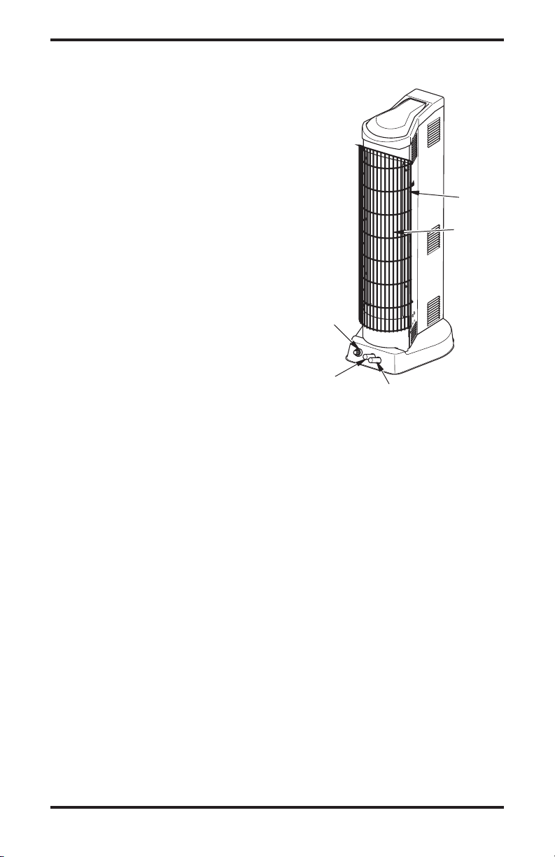
PRODUCT
IDENTIFICATION
Grill
Plaque
(behind
Grill)
Electronic
Ignitor
Manual/Auxiliary
Knob
Figure 1 - Infrared Tower Heater
On/Pilot/Off Knob
UNPACKING
1. Remove heater from carton.
2. Remove all protective packaging applied to
heater for shipment.
3. Check heater for any shipping damage. If
heater is damaged, promptly contact the dealer
to where you bought heater.
PRODUCT FEATURES
SAFETY DEVICE
This heater has a pilot with an Oxygen Depletion Sensing (ODS) safety shutoff system. The
ODS/pilot is a required feature for vent-free room
heaters. The ODS/pilot shuts off the heater if there
is not enough fresh air.
IGNITION SYSTEM
This heater has an electronic ignitor to light heater
fuel supply, which requires a AAA battery.
THERMOSTATIC HEAT CONTROL
Your unit is thermostatically controlled when heater and remote control are set to the proper modes.
This results in the greatest heater comfort.
4
www.desatech.com
113261-01A

AIR FOR COMBUSTION
AND VENTILATION
WARNING: This heater shall
not be installed in a confined
space or unusually tight construction unless provisions are provided for adequate combustion and
ventilation air. Read the following
instructions to insure proper fresh
air for this and other fuel-burning
appliances in your home.
Todayʼs homes are built more energy efficient
than ever. New materials, increased insulation and
new construction methods help reduce heat loss
in homes. Home owners weather strip and caulk
around windows and doors to keep the cold air out
and the warm air in. During heating months, home
owners want their homes as airtight as possible.
While it is good to make your home energy effi
cient, your home needs to breathe. Fresh air must
enter your home. All fuel-burning appliances need
fresh air for proper combustion and ventilation.
Exhaust fans, fireplaces, clothes dryers and fuel
burning appliances draw air from the house to
operate. You must provide adequate fresh air for
these appliances. This will insure proper venting
of vented fuel-burning appliances.
PROVIDING ADEQUATE
VENTILATION
The following are excerpts from National Fuel
Gas Code, ANSI Z223.1/NFPA 54, Section 5.3,
Air for Combustion and Ventilation.
All spaces in homes fall into one of the three fol
lowing ventilation classifications:
1. Unusually Tight Construction
2. Unconfined Space
3. Confined Space
The information on pages 5 through 7 will help
you classify your space and provide adequate
ventilation.
Unusually Tight Construction
The air that leaks around doors and windows
may provide enough fresh air for combustion and
ventilation. However, in buildings of unusually
tight construction, you must provide additional
fresh air.
Unusually tight construction is defined as
construction where:
a. walls and ceilings exposed to the out
side atmosphere have a continuous
water vapor retarder with a rating of
one perm (6 x 10
less with openings gasketed or sealed
and
b. weather stripping has been added on
openable windows and doors and
c. caulking or sealants are applied to
areas such as joints around window
and door frames, between sole plates
and floors, between wall-ceiling joints,
between wall panels, at penetrations
for plumbing, electrical and gas lines
and at other openings.
If your home meets all of these three cri
teria, you must provide additional fresh
air. See Ventilation Air From Outdoors,
page 7.
If your home does not meet all of the three
-
criteria above, proceed to Determining
Fresh-Air Flow For Heater Location.
Confined and Unconfined Space
The National Fuel Gas Code, ANSI Z223.1/NFPA 54
defines a confined space as a space whose volume
is less than 50 cubic feet per 1,000 Btu per hour
3
per kw) of the aggregate input rating of all
(4.8 m
appliances installed in that space and an unconfined
space as a space whose volume is not less than 50
cubic feet per 1,000 Btu/Hr (4.8 m
aggregate input rating of all appliances installed in
that space. Rooms communicating directly with the
space in which the appliances are installed*, through
openings not furnished with doors, are considered
-
a part of the unconfined space.
* Adjoining rooms are communicating only if
there are doorless passageways or ventilation grills
between them.
-11
kg per pa-sec-m2) or
3
per kw) of the
DETERMINING FRESH-AIR FLOW
FOR HEATER LOCATION
Determining if You Have a Confined or
Unconfined Space
Use this work sheet to determine if you have a
confined or unconfined space.
Space: Includes the room in which you will install
heater plus any adjoining rooms with doorless passageways or ventilation grills between the rooms.
-
-
www.desatech.com
5113261-01A

Or
Remove
Door into
Adjoining
Room,
Option 3
Ventilation Grills
Into Adjoining Room,
Option
2
12"
12"
Ventilation
Grills
into Adjoining
Room,
Option 1
AIR FOR COMBUSTION
AND VENTILATION
Continued
1. Determine the volume of the space (length x
width x height).
Length x Width x Height =__________cu. ft.
(volume of space)
Example: Space size 20 ft. (length) x 16 ft.
(width) x 8 ft. (ceiling height) = 2560 cu. ft.
(volume of space)
If additional ventilation to adjoining room is
supplied with grills or openings, add the volume
of these rooms to the total volume of the space.
2. Multiply the space volume by 20 to determine the
maximum Btu/Hr (kw) the space can support.
__________ (volume of space) x 20 = (Maxi-
mum Btu/Hr the space can support)
Example: 2560 cu. ft. (volume of space) x 20 =
51,200 (maximum Btu/Hr the space can support)
3. Add the Btu/Hr (kw) of all fuel burning appli
ances in the space.
Vent-free heater ________
Gas water heater* ________
Gas furnace ________
Vented gas heater ________
Gas fireplace logs ________
Other gas appliances* + ________
Total = ________
* Do not include direct-vent gas appliances. Di
rect-vent draws combustion air from the outdoors
and vents to the outdoors.
Example:
Gas water heater ___________
Vent-free heater ___________
Total ___________
4.
Compare the maximum Btu/Hr (kw) the space can
40,000 (11.7)
+ 22,000 (6.4)
= 62,000 (18.2)
support with the actual amount of Btu/Hr (kw) used.
___________
___________
Btu/Hr (kw) (maximum the space can support)
Btu/Hr (kw) (actual amount of Btu/Hr used)
Example: 51,200 Btu/Hr (15 kw) (maximum
the space can support)
62,000 Btu/Hr (18.2 kw) (actual
amount of Btu/Hr used)
The space in the above example is a confined space
because the actual Btu/Hr (kw) used is more than the
maximum Btu/Hr (kw) the space can support. You must
provide additional fresh air. Your options are as follows:
A. Rework worksheet, adding the space of an adjoin-
ing room. If the extra space provides an unconfined
space, remove door to adjoining room or add
ventilation grills between rooms. See Ventilation
Air From Inside Building.
B. Vent room directly to the outdoors. See Ventila
tion Air From Outdoors, page 7.
6
Btu/Hr (kw)
Btu/Hr (kw)
Btu/Hr (kw)
Btu/Hr (kw)
Btu/Hr (kw)
Btu/Hr (kw)
Btu/Hr (kw)
Btu/Hr (kw)
Btu/Hr (kw)
Btu/Hr (kw)
www.desatech.com
C. Install a lower Btu/Hr (kw) heater, if lower Btu/Hr
(kw) size makes room unconfined.
If the actual Btu/Hr (kw) used is less than the maxi
mum Btu/Hr (kw) the space can support, the space
is an unconfined space. You will need no additional
fresh air ventilation.
WARNING: If the area in which
the heater may be operated is
smaller than that defined as
an unconfined space or if the
building is of unusually tight
construction, provide adequate
combustion and ventilation air
by one of the methods described
in the National Fuel Gas Code,
ANSI Z223.1/NFPA 54 Section 5.3
or applicable local codes.
-
VENTILATION AIR
Ventilation Air From Inside Building
This fresh air would come from an adjoining un
confined space. When ventilating to an adjoining
unconfined space, you must provide two permanent openings: one within 12" (30.5 cm) of the
ceiling and one within 12" (30.5 cm) of the floor
on the wall connecting the two spaces (see options
1 and 2, Figure 2). You can also remove door into
-
adjoining room (see option 3, Figure 2). Follow the
National Fuel Gas Code, ANSI Z223.1/NFPA 54,
Section 5.3, Air for Combustion and Ventilation for
required size of ventilation grills or ducts.
12" (30,48 cm)
12" (30,48 cm)
Figure 2 - Ventilation Air from Inside
-
Building
113261-01A
-
-
AIR FOR COMBUSTION
Outlet
Air
Ve
ntilated
Attic
Outlet
A
ir
Inlet
Air
Inlet Air
Ve
ntilated
Crawl Space
To
Crawl
Space
To Attic
AND VENTILATION
Continued
Ventilation Air From Outdoors
Provide extra fresh air by using ventilation grills
or ducts. You must provide two permanent open
ings: one within 12" (30.5 cm) of the ceiling and
one within 12" (30.5 cm) of the floor. Connect
these items directly to the outdoors or spaces
open to the outdoors. These spaces include attics
and crawl spaces. Follow the National Fuel Gas
Code, ANSI Z223.1/NFPA 54, Section 5.3, Air for
Combustion and Ventilation for required size of
ventilation grills or ducts.
IMPORTANT: Do not provide openings for inlet
or outlet air into attic if attic has a thermostatcontrolled power vent. Heated air entering the attic
will activate the power vent.
Figure 3 - Ventilation Air from Outdoors
INSTALLATION
NOTICE: This heater is intended
for use as supplemental heat.
Use this heater along with your
primary heating system. Do not
install this heater as your pri
mary heat source. If you have a
central heating system, you may
run system’s circulating blower
while using heater. This will help
circulate the heat throughout the
house. In the event of a power
outage, you can use this heater
as your primary heat source.
-
CHECK GAS TYPE
Use only the correct type of gas (natural or propane/LP). If your gas supply is not the correct gas
type, do not install heater. Call dealer where you
bought heater for proper type heater.
-
WARNING: This appliance
is equipped for (natural or pro
pane/LP) gas. Field conversion
is not permitted.
INSTALLATION ITEMS
Before installing heater, make sure you have the
items listed below.
• for propane/LP gas, external regulator (supplied
by installer)
• piping (check local codes)
• sealant (resistant to propane/LP gas)
• equipment shutoff valve *
• ground joint union
• sediment trap
• tee joint
• pipe wrench
• for natural gas, test gauge connection*
* A CSA design-certified equipment shutoff valve
with 1/8" NPT tap is an acceptable alternative to
test gauge connection. The optional CSA designcertified equipment shutoff valve can be purchased
from your dealer. See
Accessories, page 22.
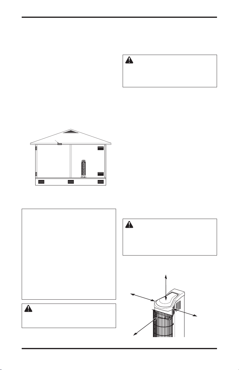
LOCATING HEATER
WARNING: Maintain the
minimum clearances shown
in Figure 4. If you can, provide
greater clearances from ceiling
and joining wall(s).
Heater may be installed either in a corner or along
the wall.
36"
10"
(25.4 cm)
(91.4 cm)
-
WARNING: A qualified service person must install heater.
Follow all local codes.
www.desatech.com
36"
(91.4 cm)
Figure 4 - Clearances to Combustibles
10"
(25.4 cm)
7113261-01A

INSTALLATION
R
E
M
OT
E
OF
F
R
EM
O
T
E
OF
F
Continued
WARNING: Never install the
heater
• in a bedroom or bathroom
• in a recreational vehicle
• where curtains, furniture,
clothing or other flammable
objects are less than 36 inches
(91.4 cm) from the front or top
of the heater or less than 10"
(25.4 cm) from sides of heater
• as a fireplace insert
• in high traffic areas
• in windy or drafty areas
CAUTION: If you install the
heater in a home garage
• heater pilot and burner must
be at least 18 inches (45.7 cm)
above floor
• locate heater where moving
vehicle will not hit it
CAUTION: This heater creates
warm air currents. These currents
move heat to wall surfaces next
to heater. Installing heater next
to vinyl or cloth wall coverings or
operating heater where impurities
(such as, but not limited to, tobacco smoke, aromatic candles,
cleaning fluids, oil or kerosene
lamps, etc.) in the air exist, may
discolor walls or cause odors.
IMPORTANT: Vent-free heaters add moisture to
the air. Although this is beneficial, installing heater
in rooms without enough ventilation air may cause
mildew to form from too much moisture. See Air
for Combustion and Ventilation, page 5. If high hu
midity is experienced, a dehumidifier may be used
to help lower the water vapor content in the air.
For convenience and efficiency, install heater
• where there is easy access for operation, inspec
tion and service
• in coldest part of room
An optional fan kit is available from your dealer.
See Accessories, page 22. If planning to use fan,
locate heater near an electrical outlet.
INSTALLING REMOTE CONTROL
RECEIVER
Remote control receiver must be installed to operate the remote control.
1. Locate receiver bracket, two packages of
AA batteries, remote receiver and screws in
hardware bag included with your heater.
2. Remove battery cover on receiver and install
batteries as shown in Figure 5. Replace battery
cover.
3. Insert wire connector and wire through bush
ing on the back of heater (see Figure 6).
4.
Lay heater onto its side. Insert wire connector
into valve at location shown in Figure 7 page 9.
Feed extra wire from receiver into heater base.
Place heater back in upright position.
5. Attach bracket around receiver with screws
as shown in Figure 6.
Receiver
AA Batteries
Battery Cover
Figure 5 - Installing Batteries in Receiver
Receiver
-
Wire
Connector
-
Receiver
Bracket
Figure 6 - Installing Remote Receiver
Bushing
-
8
www.desatech.com
113261-01A

INSTALLATION
RE
MOTE
OF
F
F
TEMPSET
ON
ROOM
OFF
MODE
SET
Continued
Bottom View
Slide Right to
REMOTE
LEARN Button (Inside)
ON
Button
Receiver Wire
Figure 7 - Connecting Receiver Wire
INSTALLING BATTERIES INTO
REMOTE
1. Locate hand-held remote control in hardware
bag included with your heater.
2. Remove battery cover and insert supplied batter
ies into remote control as shown in Figure 8.
3. Replace battery cover.
AAA
Batteries
Remote Control
Battery Cover
Figure 8 - Installing Batteries in Hand-
Held Remote Control
ACTIVATING COMMUNICATION
BETWEEN RECEIVER AND REMOTE
CONTROL
1. Set receiver selector switch to the remote
position (see Figure 9).
2. Push the ON button on hand-held remote
control. You should hear a beep. If not, use a
dull object to push the
receiver (see Figure 9). Push the ON button
on remote control once again. You should hear
a series of beeps.
If you have questions regarding the remote control
or receiver, call 1-888-673-8929.
LEARN button in the
Figure 9 - Receiver and Remote Control
REPLACING BATTERY IN IGNITOR
If the spark that lights the pilot lessons, you may need
Valve
to replace the battery in the ignitor. See Figure 10.
AAA Battery
Negative
towards cap
-
MOUNTING HEATER BASE TO
FLOOR (Where required by local codes)
1. Position heater in desired location. Mark holes
2. For carpeted floors, make a small cut with a
3. Drill 1/8" (diameter hole, 3/4" deep. (Do not
4. For concrete floors, use 1/4" diameter concrete
5. Position heater over holes. Secure to floor with
www.desatech.com
Setup
Figure 10 - Replacing Battery in
Electronic Ignitor
for drilling. Move heater aside.
sharp knife at the marked locations prior to
drilling.
use anchors in wood floors.)
drill bit. Drill 1
3
/
" deep. Insert anchors com-
8
pletely into holes.
wood screws. See Figure 11.
Wood
Screw
Mounting
Hole (One
each side)
Figure 11 - Mounting Heater to Floor
9113261-01A

INSTALLATION
Continued
CONNECTING TO GAS SUPPLY
WARNING: This appliance
requires a 3/8" NPT (National
Pipe Thread) inlet connection to
the pressure regulator.
WARNIN G: A q ua li fi ed
service person must connect
heater to gas supply. Follow all
local codes.
WARNING: For natural gas,
never connect heater to private
(non-utility) gas wells. This
gas is commonly known as
wellhead gas.
IMPORTANT: For natural gas, check gas line
pressure before connecting heater to gas line. Gas
line pressure must be no greater than 10.5 inches
(2.6 kPa) of water. If gas line pressure is higher,
heater regulator damage could occur.
CAUTION: For propane/LP
gas, never connect heater directly to the propane/LP supply.
This heater requires an external
regulator (not supplied). Install
the external regulator between the
heater and propane/LP supply.
For propane/LP gas, the installer must supply an
external regulator. The external regulator will
reduce incoming gas pressure. You must reduce
incoming gas pressure to between 11 and 14 inches
(2.7 and 3.5 kPa) of water. If you do not reduce
incoming gas pressure, heater regulator damage
could occur. Install the external regulator with
the vent pointing down as shown in Figure 12.
Pointing the vent down protects it from freezing
rain or sleet.
CAUTION: Use only new,
black iron or steel pipe. Internally-tinned copper tubing may
be used in certain areas. Check
your local codes. Use pipe of
large enough diameter to allow
proper gas volume to heater. If
pipe is too small, undue loss of
volume will occur.
Typical Inlet Pipe Diameter
All models - 1/2" or greater
Installation must include equipment shutoff valve,
union and plugged 1/8" NPT tap. Locate NPT
tap within reach for test gauge hook up. NPT tap
must be upstream from heater (see Figure 13,
page 11).
IMPORTANT: Install an equipment shutoff valve
in an accessible location. The equipment shutoff
valve is for turning on or shutting off the gas to
the appliance.
Apply pipe joint sealant lightly to male NPT
threads. This will prevent excess sealant from
going into pipe. Excess sealant in pipe could result
in clogged heater valves.
WARNING: Use pipe joint
sealant that is resistant to liquid
petroleum (LP) gas.
Propane/LP
Supply Tank
Figure 12 - External Regulator With Vent
Pointing Down
External
Regulator
Vent
Pointing
Down
10
www.desatech.com
113261-01A

INSTALLATION
Continued
Install sediment trap in supply line as shown in
Figure 13. Locate sediment trap where it is within
reach for cleaning. Locate sediment trap where
trapped matter is not likely to freeze. A sediment
trap traps moisture and contaminants. This keeps
them from going into heater controls. If sediment
trap is not installed or is installed wrong, heater
may not run properly.
IMPORTANT: Hold the pressure regulator with
wrench when connecting it to gas piping and/or
fittings. Do not over tighten pipe connection to
regulator. The regulator body could be damaged.
Pressure
Regulator
Regulator
Bracket
Heater
Cabinet
Tee Joint
Reducer
Bushing to
1/8" NPT
1/8" NPT
Plug Tap
Test Gauge Connection*
Tee Pipe Cap
Joint Nipple
Sediment Trap
Figure 13 - Gas Connection
* A CSA design-certified equipment shutoff valve
with 1/8" NPT tap is an acceptable alternative to
test gauge connection. Purchase the optional CSA
design-certified equipment shutoff valve from your
dealer. See
Accessories, page 22.
3"
(76 mm)
Min.
[7" (1.8 kPa) WC to
10.5" (2.6 kPa) WC
From External Regulator
[11" (2.7 kPa) WC to 14"
(3.5 kPa) WC Pressure]
3/8" NPT
Pipe
Nipple
Ground
Joint
Union
Equipment
Shutoff
Valve *
Natural Gas
From Gas Meter
Pressure]
Propane/LP
CHECKING GAS CONNECTIONS
WARNING: Test all gas piping
and connections, internal and
external to unit, for leaks after
installing or servicing. Correct
all leaks at once.
WARNING: Never use an open
flame to check for a leak. Apply
a noncorrosive leak detection
fluid to all joints. Bubbles forming show a leak. Correct all leaks
at once.
CAUTION: For propane/LP
gas, make sure external regula
tor has been installed between
propane/LP supply and heater.
See guidelines under
Connect-
ing to Gas Supply, page 10.
PRESSURE TESTING GAS SUPPLY
PIPING SYSTEM
Test Pressures In Excess Of 1/2 PSIG
(3.5 kPa)
1. Disconnect appliance with its appliance main
gas valve (control valve) and equipment
shutoff valve from gas supply piping system.
Pressures in excess of 1/2 psig (3.5 kPa) will
damage heater regulator.
2. Cap off open end of gas pipe where equipment
shutoff valve was connected.
3. Pressurize supply piping system by either
opening propane/LP supply tank valve for
propane/LP gas or opening main gas valve
located on or near gas meter for natural gas
or using compressed air.
4. Check all joints of gas supply piping system.
Apply a noncorrosive leak detection fluid to
all joints. Bubbles forming show a leak.
5. Correct all leaks at once.
6.
Reconnect heater and equipment shutoff valve to
gas supply. Check reconnected fittings for leaks.
113261-01A
www.desatech.com
11

INSTALLATION
Continued
Test Pressures Equal To or Less Than
1/2 PSIG (3.5 kPa)
1. Close equipment shutoff valve (see Figure 14).
2. Pressurize supply piping system by either
opening propane/LP supply tank valve for
propane/LP gas or opening main gas valve
located on or near gas meter for natural gas
or using compressed air.
3. Check all joints from gas meter for natural gas
(see Figure 15) or propane/LP supply tank for
propane/LP gas, to equipment shutoff valve
(see Figure 16). Apply a noncorrosive leak
detection fluid to all joints. Bubbles forming
show a leak.
4. Correct all leaks at once.
PRESSURE TESTING HEATER GAS
CONNECTIONS
1. Open equipment shutoff valve (see Figure 14).
2. For natural gas open main gas valve located
on or near gas meter. For propane/LP gas open
propane/LP supply tank valve.
3. Make sure control knob of heater is in the OFF
position.
4. Check all joints from equipment shutoff valve
to thermostat gas valve (see Figure 15 or 16).
Apply a noncorrosive leak detection fluid to
all joints. Bubbles forming show a leak.
5. Correct all leaks at once.
Light heater (see Operating Heater, page 13).
6.
Check all other internal joints for leaks.
7. Turn off heater (see To Turn Off Gas to Appli-
ance, page 14).
8. Replace front panel.
Equipment
Shutoff Valve
Open
Equipment
Gas
Meter
Figure 15 - Checking Gas Joints for
Propane/LP
Supply Tank
Figure 16 - Checking Gas Joints for
Shutoff
Valve
Thermostat Gas Valve
(Inside Heater)
Natural Gas
Equipment
Shutoff
Valve
Thermostat Gas Valve
(Inside Heater)
Propane/LP Gas
Closed
Figure 14 - Equipment Shutoff Valve
12
www.desatech.com
113261-01A

OPERATING HEATER
A
U
X
O
N
A
U
X
O
N
O
F
F
P
I
L
O
T
O
N
FOR YOUR SAFETY READ
BEFORE LIGHTING
WARNING: If you do not follow these instructions exactly,
a fire or explosion may result
causing property damage, per
sonal injury or loss of life.
A. This appliance has a pilot which must be
lighted by hand. When lighting the pilot,
follow these instructions exactly.
B. BEFORE LIGHTING smell all around the
appliance area for gas. Be sure to smell next
to the floor because some gas is heavier than
air and will settle on the floor.
WHAT TO DO IF YOU SMELL GAS
• Do not try to light any appliance.
• Do not touch any electric switch; do not
use any phone in your building.
• Immediately call your gas supplier from
a neighborʼs phone. Follow the gas
supplierʼs instructions.
• If you cannot reach your gas supplier, call
the fire department.
C. Use only your hand to push in or turn the
gas control knob. Never use tools. If the
knob will not push in or turn by hand, donʼt
try to repair it, call a qualified service tech
nician or gas supplier. Force or attempted
repair may result in a fire or explosion.
D. Do not use this appliance if any part has
been under water. Immediately call a
qualified service technician to inspect the
appliance and to replace any part of the
control system and any gas control which
has been under water.
LIGHTING
INSTRUCTIONS
1. STOP! Read the safety information above.
2. Make sure equipment shutoff valve is fully
open.
3. Turn pilot knob clockwise
position.
4. Wait five minutes to clear out any gas. Then
smell for gas, including near the floor. If you
smell gas, STOP! Follow “B” in the safety
information above. If you donʼt smell gas,
go to the next step.
-
to the OFF
5. Press in pilot knob and turn counterclock
wise to the PILOT position. Keep
pilot knob pressed in for five (5) seconds
(see Figure 17).
Note: You may be running this heater for
the first time after hooking up to gas supply.
If so, the pilot knob may need to be pressed
in for 30 seconds or more. This will allow
air to bleed from the gas system.
• If pilot knob does not pop up when re
leased, contact a qualified service person
or gas supplier for repairs.
6. With pilot knob pressed in, push in ignitor
button. This will light pilot. The pilot is
located at the bottom of plaque burners. If
needed, keep pressing ignitor button until
pilot lights.
Note: If pilot does not stay lit, refer to
Troubleshooting, page 17. Also contact a
qualified service person or gas supplier for
repairs. Until repairs are made, light pilot
with a match. To light pilot with a match,
see Manual Lighting Procedure, page 14.
7. Keep pilot knob pressed in for 30 seconds
after lighting pilot. After 30 seconds, release
pilot knob.
• If pilot knob does not pop up when re
leased, contact a qualified service person
or gas supplier for repairs.
Note: If pilot goes out, repeat steps 3
through 7.
-
8.
With the auxiliary knob in the ON position, turn pilot knob counterclockwise
to start the heater. The main burner
should light.
Electronic Ignitor
Button
Auxiliary
Knob
Figure 17 - Pilot Knob In The ON Position
Thermocouple
Ignitor Electrode
Pilot
Burner
-
-
-
Pilot
Knob
Figure 18 - Pilot
www.desatech.com
13113261-01A

F
TEMPSETONROOM
OFF
MODE
SET
OPERATING HEATER
Continued
9. With the auxiliary knob in the AUX posi
tion, push the ON button on the remote
control. To adjust the temperature with the
remote control, follow the instructions on
page 15. When the temperature surround
ing the remote control drops below the set
temperature, the burner should light. The
remote receiver behind the unit must be in
the REMOTE position.
CAUTION: Do not try to adjust heating levels by using the
equipment shutoff valve.
TO TURN OFF GAS
TO APPLIANCE
Shutting Off Heater
1. Press in and turn pilot knob clockwise
2. Unplug any electrical power to the appli
Shutting Off Burner Only (pilot stays lit)
If auxiliary knob is in AUX position, push OFF
button on remote control.
If auxiliary knob is in ON position, turn pilot
knob clockwise to the PILOT position.
The thermostat used on this heater senses the
room temperature at the location of the handheld remote control. At times the room may
exceed the set temperature. If so, the burner will
shut off. The burner will cycle back on when
room temperature drops below the set temperature. All plaques will turn off and on.
1. Follow steps 1 through 5 under Lighting
2. With pilot knob pressed in, strike match.
3. Keep pilot knob pressed in for 30 seconds
14
to the OFF position.
ance if service is to be performed.
THERMOSTAT
OPERATION
MANUAL LIGHTING
PROCEDURE
Instructions, page 13.
Hold match to pilot until pilot lights.
after lighting pilot. After 30 seconds, release
pilot knob. Continue with step 8 under
Lighting Instructions, above.
1. Slide selector switch on remote receiver to
-
the REMOTE position.
2. Slightly pull and turn auxiliary knob so the
AUX is to the left and right and ON is to the
top and bottom positions.
-
3. Light the pilot. Follow steps 1 through 6
under Lighting Instructions, page 13.
DISPLAY
The LCD display on the remote control indi
cates current room temperature in Fahrenheit
or Celsius. The small flame indicates burner/
valve in operation. ROOM indicates remote
is in thermo operation. TEMP appears during
manual operation. SET appears during the
time of setting the desired temperature in the
thermo operation.
Changes heater
-
from Manual
Mode to
Thermo Mode
Sets
temperature in
Thermo Mode
Figure 19 - Hand-Held Remote Control Unit
SETTING FAHRENHEIT AND CELSIUS SCALE
The factory setting for temperature is Fahrenheit. To change this setting to Celsius, press
the ON and OFF buttons on remote at the same
time. Follow the same procedure to change from
Celsius back to Fahrenheit.
MANUAL FUNCTION
On Operation
When the ON button is pressed the appliance
flame will come on. The LCD screen will show
ON for three seconds, then default to room
temperature and the word TEMP and flame
icon will show.
Off Operation
When the OFF button is pressed the appliance
flame will shut off. The LCD screen will show
OF for three seconds, then default to room tem
perature and the word TEMP will show.
www.desatech.com
HAND-HELD REMOTE
CONTROL OPERATION
-
Turns
heater
ON
Turns
heater
OFF
-
113261-01A

OPERATING HEATER
Continued
THERMOSTAT FUNCTION
Setting Desired Room Temperature
This remote control system can be thermostati
cally controlled when the remote control is in
the thermo mode. The word ROOM must be
displayed on the screen.
1. Press MODE button on remote control until
ROOM appears. This sets the remote to the
thermostat mode.
2. Press and hold the SET button until the
desired temperature is displayed. The
numbers will increase from 45° to 99° then
restart over at 45°. After releasing the SET
button, the set room temperature will dis
play for 3 seconds, then default to display
the room temperature.
Changing Set Temperature
1. Follow step two under Setting Desired Room
Temperature
2. Press the MODE button to disengage the
thermo mode. The word ROOM does
not display when thermo mode is not in
operation.
above.
INSPECTING HEATER
Check pilot flame pattern and burner flame pattern often.
PILOT FLAME PATTERN
Figure 20 shows a correct pilot flame pattern.
Figure 21 shows an incorrect pilot flame pattern.
The incorrect pilot flame is not touching the
thermocouple. This will cause the thermocouple
to cool. When the thermocouple cools, the heater
will shut down.
If pilot flame pattern is incorrect, as shown in
Figure 21
•
turn heater off (see To Turn Off Gas to Appliance,
page 14)
• see Troubleshooting, page 17
Note: The pilot flame on natural gas units will
have a slight curve, but flame should be blue and
have no yellow or orange color.
Blue Flame
Thermocouple
-
Figure 20 - Correct Pilot Flame Pattern
Thermocouple
Figure 21 - Incorrect Pilot Flame Pattern
-
Pilot Burner
Yellow Flame
Pilot Burner
BURNER FLAME PATTERN
Figure 22 shows a correct and incorrect burner flame
pattern. If burner flame pattern is incorrect
• turn heater off (see To Turn Off Gas to Appli
ance, page 14)
• see Troubleshooting
Correct
Flame
Pattern
Figure 22 - Burner Operation
, page 17
Incorrect
Flame
Pattern
-
www.desatech.com
15113261-01A

CLEANING AND
MAINTENANCE
WARNING: Turn off heater
and let cool before cleaning.
CAUTION: You must keep control areas, burner and circulating
air passageways of heater clean.
Inspect these areas of heater
before each use. Have heater
inspected yearly by a qualified
service person. Heater may need
more frequent cleaning due to
excessive lint from carpeting,
bedding material, pet hair, etc.
WARNING: Failure to keep
the primary air opening(s) of
the burner(s) clean may result in
sooting and property damage.
ODS/PILOT AND BURNER
Use a vacuum cleaner, pressurized air or small,
soft bristled brush to clean.
BURNER PILOT AIR INLET
The primary air inlet holes allow the proper
amount of air to mix with the gas. This provides a
clean burning flame. Keep these holes clear of dust,
dirt and lint. Clean these air inlet holes prior to each
heating season. Blocked air holes will create soot.
We recommend that you clean the unit every three
months during operation and have heater inspected
yearly by a qualified service person.
We also recommend that you keep the burner
tube and pilot assembly clean and free of dust and
dirt. To clean these parts we recommend using
compressed air no greater than 30 PSI (200 kPa).
Your local computer store, hardware store or home
center may carry compressed air in a can. You can
use a vacuum cleaner in the blow position. If using
compressed air in a can, please follow the direc
tions on the can. If you don't follow directions on
the can, you could damage the pilot assembly.
1. Shut off the unit, including the pilot. Allow
the unit to cool for at least thirty minutes.
2. Inspect burner, pilot for dust and dirt.
3. Blow air through the ports/slots and holes in
the burner.
4. Never insert objects into the pilot tube.
Clean the pilot assembly also. A yellow tip on the
pilot flame indicates dust and dirt in the pilot as
sembly. There is a small pilot air inlet about two
inches from where the pilot flame comes out of
the pilot assembly (see Figure 23). With the unit
off, lightly blow air through the air inlet. You may
blow through a drinking straw if compressed air
is not available.
Pilot Assembly
Pilot Air Inlet
Figure 23 - Pilot Air Inlet
CABINET
Air Passageways
Use a vacuum cleaner o r pressurized air to
clean.
Exterior
Use a soft cloth dampened with a mild soap and
water mixture. Wipe the cabinet to remove dust.
BATTERIES
During long periods of time when the heater is
not being used, take batteries out of receiver and
ignitor. Remove exhausted batteries immediately.
Do not mix old and new batteries.
SERVICE HINTS
When Gas Pressure Is Too Low
• pilot will not stay lit
• burner will have delayed ignition
• heater will not produce specified heat
• propane/LP gas supply may be low
You may feel your gas pressure is too low. If so, con
tact your local natural or propane/LP gas supplier.
TECHNICAL SERVICE
-
You may have further questions about installation,
operation or troubleshooting. If so, contact DESA
Heating Productsʼ Technical Service Department
at 1-866-672-6040. When calling please have your
model and serial numbers of your heater ready.
You can also visit DESA Heating Productsʼ techni
cal service web site at www.desatech.com.
-
-
-
16
www.desatech.com
113261-01A

TROUBLESHOOTING
WARNING: Turn off and unplug heater and let cool before servicing.
Only a qualified service person should service and repair heater.
CAUTION: Never use a wire, needle or similar object to clean
ODS/pilot. This can damage ODS/pilot unit.
Note: All troubleshooting items are listed in order of operation.
OBSERVED PROBLEM
When ignitor button is pressed
in, there is no spark at ODS/
pilot
When ignitor button is pressed
in, there is a spark at ODS/Pilot
but no ignition
POSSIBLE CAUSE
1. Ignitor electrode positioned
wrong
2. Ignitor electrode broken
3. Ignitor elect rode not con
nected to ignitor cable
4. Ignitor cable pinched or wet
5. Broken ignitor cable
6. Bad ignitor
7. Battery not installed, battery
power low or battery not in
stalled correctly
1. Gas supply turned off or equip
ment shutoff valve closed
2. Pilot knob not fully pressed in
while pressing ignitor button
3. Air in gas lines when in
stalled
4. Depleted gas supply (propane/
LP gas)
5. ODS/pilot is clogged
6. Gas regulator setting is not
correct
REMEDY
1. Replace pilot assembly
2. Replace pilot assembly
3. Reconnect ignitor cable
-
4. Free ignitor cable if pinched
by any metal or tubing. Keep
ignitor cable dry
5. Replace ignitor cable
6. Replace ignitor
7. Install new alkaline battery in
electronic ignitor. Verify bat
tery is installed correctly. See
page 9
1. Turn on gas supply or open
equipment shutoff valve
2. Turn to PILOT/IGN position.
Fully press in pilot knob while
pressing ignitor button
-
3. Continue holding down pilot
knob. Repeat igniting operation until air is removed
4. Contact local propane/LP gas
company
5. Clean ODS/pilot (see Cleaning
and Maintenance, page 16) or
replace ODS/pilot assembly
6. Replace gas regulator
-
www.desatech.com
17113261-01A

OBSERVED PROBLEM
ODS /pilot lights but flame
goes out when control knob is
released
TROUBLESHOOTING
Continued
POSSIBLE CAUSE
1.
Pilot knob not fully pressed in
2. Pilot knob not pressed in long
enough
3. Equipment shutoff valve not
fully open
4. Thermoco upl e conne ction
loose at control valve
5. Pilot flame not touching ther
mocouple, which allows ther
mocouple to cool, causing
pilot flame to go out. This
problem could be caused by
one or both of the following:
A) Low gas pressure
B) Dirty or partially clogged
ODS/pilot
6. Thermocouple damaged
7. Valve damaged
-
-
REMEDY
1. Press in pilot knob fully
2. After ODS/pilot lights, keep pilot knob pressed in 30 seconds
3. Fully open equipment shutoff
valve
4. Hand tighten until snug, then
tighten 1/4 turn more
5. A) Contact local natural or
propane/LP gas company
B) Cle a n ODS/pi l ot (see
Cleaning and Maintenance
page 16) or replace ODS/pilot
assembly
6. Replace pilot assembly
7. Replace valve
,
Burner(s) does not light after
ODS/pilot is lit
Delayed ignition of burner(s)
Burner backfiring during com
bustion
Burner plaque(s) does not glow
Slight smoke or odor during
initial operation
Heater produces a clicking/tick
ing noise just after burner is lit
or shut off
1. Burner orifice(s) is clogged
2. Inlet gas pressure is too low
1. Manifold pressure is too low
2. Burner orifice(s) is clogged
1. Burner orifice(s) is clogged or
damaged
2. Burner damaged
3. Gas regulator defective
1. Plaque damaged
2. Inlet gas pressure is too low
1. Residues from manufacturing
processes
1. Metal expanding while heating
or contracting while cooling
1.
Clean burner orifice(s) (see
Cleaning and Maintenance, page
16) or replace burner orifice(s)
2. Contact local natural or propane/LP gas company
1. Contact local natural or pro
pane/LP gas company
2.
Clean burner orifice(s) (see
Cleaning and Maintenance, page
16) or replace burner orifice(s)
1.
Clean burner orifice(s) (see
Cleaning and Maintenance, page
16) or replace burner orifice(s)
2. Replace burner
3. Replace gas regulator
1. Replace burner
2. Contact local natural or pro
pane/LP gas company
1. Problem will stop after a few
hours of operation
1. This is common with most heat
ers. If noise is excessive, contact
qualified service person
-
-
-
18
www.desatech.com
113261-01A

TROUBLESHOOTING
Continued
WARNING: If you smell gas
• Shut off gas supply.
• Do not try to light any appliance.
• Do not touch any electrical switch; do not use any phone in your
building.
• Immediately call your gas supplier from a neighbor’s phone. Follow the gas supplier’s instructions.
• If you cannot reach your gas supplier, call the fire department.
IMPORTANT: Operating heater where impurities in air exist may create odors. Cleaning supplies,
paint, paint remover, cigarette smoke, cements and glues, new carpet or textiles, etc., create fumes.
OBSERVED PROBLEM
Remote does not function
POSSIBLE CAUSE
1. Battery is not installed or batter power is low
REMEDY
1. Replace AA batteries in receiver
and remote hand set
White powder residue forming
within burner box or on adjacent
walls or furniture
Heat er pr oduce s u nwant ed
odors
Heater shuts off in use (ODS
operates)
Gas odor even when pilot knob
is in OFF position
Gas odor during combustion
1. When heated, vapors from
furniture polish, wax, carpet
cleaner, etc., may turn into
white powder residue
1. Heater burning vapors from
paint, hair spray, glues, etc.
See IMPORTANT statement
above
2. Low fuel supply (propane/LP
gas)
3. Gas le ak. Se e War ning
statement at top of page
1. Not enough fresh air is avail
able
2. Low line pressure
3. O D S/ p il ot i s p a rt ia ll y
clogged
1. Gas le ak. Se e War ning
statement at top of page
2. Valve defective
1. Foreign matter between valve
and burner
2. Gas le ak. Se e War ning
statement at top of page
1. Turn heater off when using
furniture polish, wax, carpet
cleaners or similar products
1. Ventilate room. Stop using
odor causing products while
heater is running
2. Refill supply tank
3. Locate and correct all leaks
(see Checking Gas Connec
tions, page 11)
1. Open window and/or door for
ventilation
2. Contact local natural or pro
pane/LP gas company
3. Clean ODS/pilot (see Cleaning
and Maintenance, page 16)
1. Locate and correct all leaks
(see Checking Gas Connec
tions, page 11)
2. Replace valve
1. Take apart gas tubing and
remove foreign matter
2. Locate and correct all leaks
(see Checking Gas Connec
tions, page 11)
-
-
-
-
Moisture/condensation noticed
on windows
1. Not enough combustion/ven
tilation air
www.desatech.com
1. Refer to Fresh Air for Com
bustion and Ventilation re
quirements (page 5)
-
-
19113261-01A

ILLUSTRATED PARTS BREAKDOWN
2
3
4
5
6
14
15
16
17
16
19
18
25
26
22
24
12
13
21
20
20
7
8
9
10
31
37
34
35
36
32
33
1
11
27
28
29
30
28
23
F
T
E
M
P
S
E
T
O
N
RO
O
M
O
F
F
M
O
D
E
S
E
T
MODELS
CTR25NR, VTN25R, CTR22PR AND VTP22R
20
www.desatech.com
113261-01A
PARTS LIST
This list contains replaceable parts used in your heater. When ordering parts, follow the instructions
listed under Replacement Parts on page 22 of this manual.
PART NUMBER
KEY CTR25NR CTR22PR
NO. VTN25R VTP22R DESCRIPTION QTY
1 113079-01 113079-01 Grill 1
2 113601-02DC 113601-02DC Cast Top 1
3 113602-01CK 113602-01CK Perforated Top 1
4 113078-02CK 113078-02CK Deflector Trim Plate 1
5 ** ** Wrapper 1
6 113651-01CK 113651-01CK Top Trim 1
7 113600-03DC 113600-03DC Back Door 1
8 114659-01 114659-01 Grill Screws 2
9 114032-01 114032-01 Receiver Remote 1
10 113255-01DC 113255-01DC Remote Receiver Plate 1
11 M50104-06 M50104-06 Bushing 1
12 114254-01 114254-01 Top Burner Assembly 1
13 114254-02 114254-02 Bottom Burner Assembly 1
14 114255-01 114255-01 Reflector Assembly 1
15 113175-01CK 113175-01CK Top Baffle 1
16 113175-02 113175-02 Mid Burner Baffle 2
17 113175-03 113175-03 Between Burner Baffle 1
18 113176-01 113176-01 Plaque Clip 6
19 113074-02DC 113074-02DC Bottom Trim 1
20 099056-24 099056-25 Injector 2
21 113258-01 113258-01 Outlet Tube 1
22 113650-02CK 113650-02CK Trim Deflector Plate 1
23 113173-01 113173-01 Pilot Bracket 1
24 110803-03 110803-02 ODS Pilot 1
25 109121-02 109121-02 Pilot Shield 1
26 098271-11 098271-11 Ignitor Cable 1
27 099387-13 099387-13 Pilot Tube 1
28 111435-01 111435-01 Electronic Ignitor 1
29 114021-01 114021-01 Auxiliary Knob Extension 1
30 114021-02 114021-02 Pilot Knob Extension 1
31 ** ** Base 1
32 113172-01 113172-01 Regulator Bracket 1
33 099415-21 099415-18 Gas Regulator 1
34 114250-01 114250-01 Inlet Tube 1
35 098264-02 098264-02 Male Connector 2
36 114012-01 114012-01 Valve 1
37 114031-01 114031-01 Hand-Held Remote 1
PARTS AVAILABLE - NOT SHOWN
113262-01 113262-01 Control Decal 1
113264-01 113264-01 Lighting Inst Hang Tag English 1
113264-02 113264-02 Lighting Inst Hang Tag Spanish 1
105345-01 105345-01 Wire Tie 1
** Not a field replaceable part.
www.desatech.com
21113261-01A

SPECIFICATIONS
CTR25NR CTR22PR
VTN25R VTP22PR
Btu/hr (kW) 25,000 (7.3) 22,000 (6.4)
Type Gas Natural Only Propane/LP Only
Ignition Electronic Electronic
Pressure Regulator Setting 6" W.C. (1.5 kPa) 8" W.C. (2.0 kPa)
Inlet Gas Pressure* (in. of water)
Maximum 10.5" (7.6 kPa) 14" (3.5 kPa)
Minimum 7" (1.8 kPa) 11" (2.7 kPa)
Dimensions (H x W x D)
Heater 40
102.9 x 38.1 x 48.3 cm 102.9 x 38.1 x 48.3 cm
Carton 45
115.9 x 44.5 x 55.2 cm 115.9 x 44.5 x 55.2 cm
Weight
Heater 28 lbs. (12.7 kg) 28 lbs. (12.7 kg)
Shipping 33 lbs. (15 kg) 33 lbs. (15 kg)
Note: Dimensions listed are outer most points on the heater (includes control knobs and grill).
* For purposes of input adjustment.
1
/2" x 15" x 19" 40 1/2" x 15" x 19"
5
/8" x 17 1/2" x 21 3/4" 45 5/8" x 17 1/2" x 21 3/4"
ACCESSORIES
Purchase these heater accessories from your local
dealer. If they can not supply these accessories, either
contact your nearest Parts Central (see page 23) or
call DESA Heating Products at 1-866-672-6040 for
referral information. You can also write to the address
listed on the back page of this manual.
EQUIPMENT SHUTOFF VALVE
GA5010
For all models. Equipment shutoff valve with
1/8" NPT tap.
FAN KIT - GA3220T
For all models. Provides better heat distribution.
Makes heater more efficient. Complete installation
and operating instructions included.
Thermostatically-controlled, blower turns itself on
and off as required.
SERVICE PUBLICATIONS
You can purchase a service manual from the address
listed on the back page of this manual. Send a check
for $5.00 payable to DESA Heating Products.
REPLACEMENT PARTS
Note: Use only original replacement parts. This
will protect your warranty coverage for parts
replaced under warranty.
PARTS UNDER WARRANTY
Contact authorized dealers of this product. If
they canʼt supply original replacement part(s),
call DESA Heating Productsʼ Technical Service
Department at 1-866-672-6040.
When calling DESA Heating Products, have ready
• your name
• your address
• model and serial numbers of your heater
• how heater was malfunctioning
• type of gas used (propane/LP or natural gas)
• purchase date
Usually, we will ask you to return the part to the
factory.
PARTS NOT UNDER WARRANTY
Contact authorized dealers of this product. If they
canʼt supply original replacement part(s), either
contact your nearest Parts Central (see page 23)
or call DESA Heating Products at 1-866-672-6040
for referral information.
When calling DESA Heating Products, have ready
• model number of your heater
• the replacement part number
22
www.desatech.com
113261-01A

PARTS CENTRAL
These Parts Centrals are privately owned businesses. They have agreed to support our customerʼs needs
by providing original replacement parts and accessories.
Tools & Equipment Co.
5 Manila Ave
Hamden, CT 06514-0322
1-800-397-7553
203-248-7553
Portable Heater Parts
342 N. County Rd. 400 East
Valparaiso, IN 46383-9704
219-462-7441
1-888-619-7060
www.portableheaterparts.com
sales@portableheaterparts.com
techservice@portableheaterparts.com
FBD
1349 Adams Street
Bowling Green, KY 42103-3414
270-846-1199
1-800-654-8534
Fax: 1-800-846-0090
franktalk@aol.com
Master Parts Dist.
1251 Mound Ave. NW
Grand Rapids, MI 49504-2672
616-791-0505
1-800-446-1446
www.nbmc.com
Washer Equipment Co.
1715 Main Street
Kansas City, MO 64108-2195
KS, MO, AR
816-842-3911
www.washerparts.com
East Coast Energy
707 Broadway
W. Long Branch, NJ 07764-1542
732-870-8809
1-800-755-8809
www.njplaza.com/ecep
21st Century
2950 Fretz Valley Road
Perkasie, PA 18944-4034
215-795-0400
800-325-4828
Laporte’s Parts & Service
2444 N. 5th Street
Hartsville, SC 29550-7704
843-332-0191
Parts Department
Cans Unlimited
P.O. Box 645
Taylor, SC 29687-0013
803-879-3009
1-800-845-5301
cuisales@aol.com
www.desatech.com
23113261-01A

Patent Pending
2701 Industrial Drive
P.O. Box 90004
Bowling Green, KY 42102-9004
www.desatech.com

CALENTADOR DE GAS INFRARROJO NO VENTILADO
(SIN VENTILAS)
INFORMACIÓN DE SEGURIDAD Y MANUAL DE INSTALACIÓN
MODELOS CTR25NR, CTR22PR, VTN25R Y VTP22R
ADVERTENCIA: Si la información contenida en este manual
no se sigue al pie de la letra, se puede producir un incendio
o una explosión que podría ocasionar daños a la propiedad,
lesiones personales o la pérdida de la vida.
— No guarde ni utilice gasolina u otros vapores y líquidos
inflamables cerca de este aparato ni de cualquier otro.
— QUÉ HACER SI PERCIBE OLOR A GAS
• No intente encender ningún aparato.
• No toque ningún interruptor eléctrico; no use ningún
teléfono en el edificio.
• Llame inmediatamente a su proveedor de gas desde
el teléfono de algún vecino. Siga las instrucciones del
proveedor de gas.
• Si no puede localizar al proveedor de gas, llame al
departamento de bomberos.
— La instalación y el servicio deben ser realizados por un
instalador capacitado, agencia de servicio o por el pro
-
veedor de gas.
Guarde este manual para futuras referencias.
Para obtener más información, visite www.desatech.com

ADVERTENCIA: La instalación, ajuste, alteración, servicio o
mantenimiento inadecuados pueden provocar lesiones o daños a la propiedad. Consulte este manual para conocer los procedimientos correctos de instalación y operación. Para obtener
asistencia o información adicional consulte a un instalador
capacitado, agencia de servicio o al proveedor de gas.
ADVERTENCIA: Este es un calentador de llama de gas sin
ventilación. Utiliza aire (oxígeno) del cuarto en el que se instala. Se deben tomar las medidas necesarias para asegurar la
cantidad de aire para una ventilación y combustión adecuadas. Consulte la sección Aire para combustión y ventilación,
en la página 5 de este manual.
Este aparato puede ser instalado en una casa móvil con ubicación permanente y adquirida en el mercado de posventa*,
siempre que no esté prohibido por los códigos locales.
Este aparato está diseñado para usarse únicamente con el tipo
de gas indicado en la placa de clasificación. Este aparato no
se puede convertir para su uso con otros gases.
* Mercado de posventa: venta completada por parte del fabricante, sin fines de reventa
TABLA DE CONTENIDO
Información de seguridad .................................... 2
Códigos locales .................................................. 4
Identificación del producto ................................... 4
Desempaque ...................................................... 4
Características del producto ................................ 4
Aire para combustión y ventilación ..................... 5
Instalación .......................................................... 7
Funcionamiento del calentador ......................... 13
Inspección del calentador ................................. 15
Limpieza y mantenimiento ................................. 16
INFORMACIÓN DE SEGURIDAD
ADVERTENCIA: Este producto
contiene y/o genera químicos que el
Estado de California reconoce que
causan cáncer, defectos de nacimiento u otros daños relacionados
con la reproducción.
2
www.desatech.com
Consejos para reparaciones ............................ 16
Servicio técnico ................................................ 16
Solución de problemas ...................................... 17
Clasificación ilustrada de piezas y lista de piezas
Especificaciones ................................................ 22
Accesorios ........................................................ 22
Publicaciones para servicio .............................. 22
Piezas de repuesto ........................................... 23
Central de piezas ............................................. 23
.. 20
IMPORTANTE: Lea este manual del
propietario cuidadosa y completamente antes de intentar ensamblar, operar
o dar servicio a este calentador. El uso
inadecuado de este calentador puede
causar lesiones graves o la muerte
por quemaduras, incendio, explosión,
electrocución e intoxicación con mo
nóxido de carbono.
113261-01A
-

INFORMACIÓN DE SEGURIDAD
Continuación
PELIGRO: La intoxicación
con monóxido de carbono puede
resultar en la muerte!
Intoxicación con monóxido de carbono: Los síntomas
iniciales de la intoxicación con monóxido de carbono son
semejantes a los de la gripe, con dolores de cabeza, mareos
y/o náusea. Si usted presenta estos síntomas, es posible que
el calentador no esté funcionando correctamente. ¡Respire
aire fresco inmediatamente! Haga que le den servicio al
calentador. El monóxido de carbono afecta más a algunas
personas que a otras. Las más afectadas incluyen a mujeres
embarazadas, personas con enfermedades del corazón o
de los pulmones o anemia, aquellas bajo la influencia del
alcohol y aquellas a grandes altitudes.
Gas natural y propano o gas LP: Los gases natural y
propano o gas LP son gases inodoros. A estos gases se
les agrega un agente oloroso. El olor le ayuda a detectar
las fugas de gas. Sin embargo, el olor que se añade al gas
puede desvanecerse. Es posible que haya gas presente
aunque no haya ningún olor.
Asegúrese de leer y comprender todas las advertencias.
Conserve este manual para consulta. Es su guía para la
operación segura y correcta de este calentador.
ADVERTENCIA: Cualquier
cambio a este calentador o a los
controles puede ser peligroso.
ADVERTENCIA: No utilice
un aditamento de ventilador, de
intercambio de calor ni otro accesorio que no esté aprobado para
su uso con este calentador.
Debido a las altas temperaturas,
el aparato debe situarse fuera de
las rutas de paso y alejado de los
muebles y cortinas.
No ponga ropa ni otros materiales
inflamables sobre el aparato o cerca
del mismo. Nunca coloque ningún
objeto sobre el calentador.
La superficie del calentador alcanza
temperaturas muy altas cuando éste
está funcionando. Mantenga niños y
adultos alejados de las superficies
calientes para evitar quemaduras o
que la ropa se encienda. El calentador permanecerá caliente durante
algún tiempo después de que se
haya apagado. Deje que la superficie
se enfríe antes de tocarla.
Supervise con sumo cuidado a los
niños pequeños cuando estén en el
mismo cuarto que el calentador.
Asegúrese que el resguardo de la
rejilla esté puesto antes de hacer
funcionar el calentador.
Mantenga el área del aparato limpia
y libre de materiales combustibles,
gasolina y otros vapores y líquidos
inflamables.
1. Este aparato está diseñado para usarse únicamente con el tipo de gas indicado en la placa de
clasificación. Este aparato no se puede convertir
para su uso con otros gases.
2. No ponga los tanques de suministro de propano
o gas LP dentro de ninguna estructura. Sitúe los
tanques de suministro de propano o gas LP en el
exterior.
3. Este calentador no se debe instalar en un recá
mara o en un baño.
4. Si percibe olor a gas
• Cierre el suministro de gas
• No intente encender ningún aparato
• No toque ningún interruptor eléctrico; no use
ningún teléfono en el edificio
• Llame inmediatamente a su proveedor de gas
desde el teléfono de algún vecino. Siga las
instrucciones del proveedor de gas
• Si no puede localizar al proveedor de gas, llame
al departamento de bomberos
5. Este calentador necesita de ventilación de aire
fresco del exterior para poder funcionar correc
tamente. Este calentador tiene un sistema de
apagado de seguridad con Sensor de agotamiento
de oxígeno (ODS). El ODS apaga el calentador
cuando éste no cuenta con suficiente aire fresco.
Consulte Aire para combustión y ventilación,
página 5.
-
-
www.desatech.com
3113261-01A
INFORMACIÓN DE SEGURIDAD
Continuación
6. Mantenga limpias y libres de residuos todas las
aberturas de las partes anterior e inferior del ca
lentador. Esto asegurará que haya suficiente aire
para lograr una combustión adecuada.
7. Si el calentador se apaga, no lo vuelva a encender
hasta que éste cuente con aire fresco del exterior. Si el
calentador se sigue apagando, haga que lo reparen.
8. No haga funcionar el calentador
• Donde se utilicen o almacenen líquidos o vapores
inflamables
• En condiciones con mucho polvo
9. No use el calentador si cualquiera de sus partes ha
estado sumergida bajo el agua. Llame inmediatamente
a un técnico capacitado de servicio para que inspec
cione el calentador de cuartos y para que reemplace
las piezas del sistema de control o los controles de gas
que hayan estado sumergidos en el agua.
10. Apague el calentador y deje que se enfríe antes de
repararlo. Sólo una persona de servicio capacitada
debe repararlo o darle servicio.
11. Hacer funcionar el calentador a alturas superiores
a 1.371 metros (4.500 pies) puede ocasionar que
el piloto se apague.
12. Para prevenir problemas de rendimiento, no use
tanques de propano o gas LP de menos de 690 kPa
(100 psi) de capacidad.
13. Apague el calentador antes de usar pulidores de
muebles, ceras, limpiadores de alfombras o pro
ductos parecidos. Si se calientan, los vapores que se
desprenden de estos productos pueden producir un
residuo de polvo blanco en el interior de la caja del
calentador o en las paredes o muebles adyacentes.
14. Procure que se cumplan las distancias mínimas
alrededor de las aberturas para el aire.
CÓDIGOS LOCALES
Instale y use el calentador con cuidado. Siga todos
los códigos locales. A falta de códigos locales,
utilice la última edición del Código Nacional de
Gas Combustible, ANSI Z223.1/NFPA 54*.
*Lo puede obtener de:
American National Standards Institute, Inc.
National Fire Protection Association, Inc.
4
1430 Broadway
New York, NY 10018, EE.UU.
Batterymarch Park
Quincy, MA 02269, EE.UU.
www.desatech.com
IDENTIFICACIÓN DEL
PRODUCTO
-
Placa
(detrás de
la parrilla)
-
Encendedor
electrónico
Perilla manual
auxiliar
Figura 1. Calentador infrarrojo en torre
Perilla de On (encendido)/
Pilot (piloto)/Off (apagado)
DESEMPAQUE
1. Saque el calentador de la caja.
-
2. Retire todo el empaque de protección que se
agregó al calentador para su envío.
3.
Revise el calentador para ver si hay algún daño debido
al transporte. Si el calentador está dañado, contacte
de inmediato al distribuidor a quien lo compró.
CARACTERÍSTICAS DEL
PRODUCTO
DISPOSITIVO DE SEGURIDAD
Este calentador tiene un piloto con un sistema de
apagado de seguridad con Sensor de agotamiento de
oxígeno (ODS, por sus siglas en inglés). El piloto con
ODS es una característica necesaria de los calentadores
sin ventilación para cuartos. El piloto con ODS apaga
el calentador cuando no hay suficiente aire fresco.
SISTEMA DE ENCENDIDO
Este calentador tiene un encendedor electrónico
para prender el suministro de combustible del
calentador, lo cual requiere de una batería AAA.
CONTROL DE CALOR TERMOSTÁTICO
Su unidad está controlada de manera termostática
cuando el calentador y su control remoto están
configurados en los modos apropiados. Esto ofrece
la mayor comodidad de uso del calentador.
113261-01A
Parrilla

AIRE PARA COMBUSTIÓN
Y VENTILACIÓN
ADVERTENCIA: Este calentador
no debe instalarse en un espacio con
finado o en una construcción inusualmente sellada a menos que se hayan
tomado medidas para proporcionar
el aire adecuado para combustión y
ventilación. Lea las instrucciones a
continuación para asegurarse de que
su hogar cuente con la cantidad ade
cuada de aire fresco para éste y otros
aparatos que quemen combustible.
Hoy más que nunca, las casas están diseñadas para ser más
eficientes en términos de energía. Los nuevos materiales,
un mejor aislamiento y los nuevos métodos de construcción ayudan a reducir la pérdida de calor en las casas. Los
propietarios de las casas colocan tiras aislantes y sellan los
bordes de las ventanas para mantener el aire frío afuera
y el aire caliente adentro. Durante los meses cálidos, los
propietarios de las casas quieren que éstas estén lo más
aisladas que sea posible de filtraciones de aire.
Aunque es bueno hacer que su casa sea eficiente en
términos energéticos, ésta también necesita respirar. Es
necesario que entre aire fresco a su casa. Todos los apa
ratos que queman combustible necesitan de aire fresco
para tener una combustión y ventilación adecuadas.
Los ventiladores de expulsión de aire, las chimeneas, las
secadoras de ropa y los aparatos que queman combus
tible toman aire de la casa durante su funcionamiento.
Usted debe procurar la cantidad adecuada de aire fresco
para estos aparatos. Esto asegurará que haya ventilación
adecuada para los aparatos que queman combustible.
CÓMO PROCURAR LA
VENTILACIÓN ADECUADA
A continuación se incluyen extractos del Código Nacional de Gas Combustible, ANSI Z223.1/NFPA 54,
sección 5.3, Aire para combustión y ventilación
Todos los espacios en las casas se pueden clasificar en
una de las tres categorías de ventilación siguientes:
1. Construcción inusualmente sellada
2. Espacio no confinado
3. Espacio confinado
La información de las páginas 5 a la 7 le ayudará a clasificar su espacio y a proporcionar la ventilación adecuada.
Construcción inusualmente sellada
El aire que se filtra por los bordes de las puertas y
ventanas puede proporcionar suficiente aire fresco
para la combustión y la ventilación. Sin embargo,
en los edificios que tienen una construcción in
-
-
-
-
.
-
www.desatech.com
usualmente sellada, usted debe procurar la entrada
de aire fresco adicional.
Una construcción inusualmente sellada se
define como aquella en la que:
a.
las paredes y los techos que están expuestos
a la atmósfera exterior tienen un retardante
continuo de vapor de agua con una clasificación de un perm (6 x 10
menos con aberturas selladas o con juntas
b. se han instalado tiras de aislamiento en
las ventanas que se pueden abrir y en las
puertas, y
c. se han puesto selladores en áreas tales
como las uniones alrededor de los marcos
de puertas y ventanas, entre las placas de
base y el suelo, entre las uniones de las
paredes con el techo, entre los paneles
de las paredes, en las perforaciones para
tubería de agua, líneas eléctricas y de gas,
y en otras aberturas.
Si su casa cumple con estos tres criterios,
usted deberá procurar la entrada de aire fres
co adicional. Consulte Aire del exterior para
ventilación, página 7.
Si su casa no cumple con los tres criterios
anteriores, proceda a la Determinación del flujo
de aire fresco para ubicar el calentador.
Espacio confinado o no confinado
El Código Nacional de Gas Combustible, ANSI Z223.1/
NFPA 54 define el espacio confinado como aquel cuyo
volumen es menor de 50 pies cúbicos por cada 1.000
BTU/h (4,8 m
de todos los aparatos instalados en ese espacio y define el
espacio no confinado como aquel cuyo volumen no es
menor de 50 pies cúbicos por 1,000 BTU/h (4,8 m
de clasificación de entrada agregada de todos los aparatos
instalados en ese espacio. Los cuartos que se comunican
directamente con el espacio en el que los aparatos están
instalados,* por medio de aberturas que no tengan puertas,
se consideran parte del espacio no confinado.
* Se considera que los cuartos adyacentes se comuni
can únicamente si hay accesos sin puerta o rejillas de
ventilación entre ellos.
3
por kw) de clasificación de entrada agregada
11
kg por pa seg m2) o
3
por kw)
DETERMINACIÓN DEL FLUJO DE AIRE
FRESCO PARA UBICAR EL CALENTADOR
Cómo determinar si tiene un espacio
confinado o no confinado
Utilice esta hoja de trabajo para determinar si tiene
un espacio confinado o no confinado.
Espacio: incluye el cuarto en el que se va a insta-
lar el calentador más los cuartos adyacentes que
tengan accesos sin puerta o rejillas de ventilación
entre ellos.
y
-
-
5113261-01A

Or
Remove
Door into
Adjoining
Room,
Option 3
Ventilation Grills
Into Adjoining Room,
Option
2
12"
12"
Ventilation
Grills
into Adjoining
Room,
Option 1
AIRE PARA COMBUSTIÓN
Y VENTILACIÓN
Continuación
1.
Determine el volumen del espacio (largo x ancho x
altura).
Largo x ancho x altura =__________ m3 (pies cúbicos)
(volumen del espacio)
Ejemplo: tamaño del espacio, largo: 20 pies (6,1 m);
x ancho: 16 pies (4,88 m); x altura del techo: 8 pies
(2,44 m) = 2560 pies cúbicos (72,49 m
del espacio)
Si se proporciona ventilación adicional a los cuartos
adyacentes, agregue el volumen de dichos cuartos al
volumen total del espacio.
2. Multiplique el volumen del espacio por 20 para deter
minar la cantidad máxima de BTU/h que el espacio
puede admitir.
__________(volumen de espacio) x 20 = [BTU/h (kw)
máximo que el espacio puede admitir]
Ejemplo: 2560 pies cúbicos (72,49 m3) (volumen del
espacio) x 20 = 51.200 [cantidad máxima de BTU/h
(kw) que el espacio puede admitir]
3. Agregar la cantidad de BTU/h de todos los aparatos
que queman combustible en ese espacio.
Calentador sin ventila _________ BTU/h (kw)
Calentador de gas para agua* _________BTU/h (kw)
Horno de gas _________ BTU/h (kw)
Calentador de gas con ventila _________BTU/h (kw)
Troncos para chimenea de gas _________BTU/h (kw)
Otros aparatos para gas* + ________ BTU/h (kw)
Total = ________BTU/h (kw)
* No incluya los aparatos de gas con ventilación directa. El
sistema de ventilación directa toma el aire para combustión
del exterior y ventila hacia el exterior.
Ejemplo:
Calentador para agua de gas _________
Calentador sin ventilas _________
Total _________
4.
Compare la cantidad máxima de BTU/h que el espacio pue-
40.000 (11.7)
+ 22.000 (6.4)
= 62.000 (18.2)
de admitir con la cantidad real de BTU/h que se utiliza.
_________BTU/h (máximo admitido por el espacio)
_________
BTU/h (cantidad real de BTU/h que se utiliza)
Ejemplo: 51,200 BTU/h (15 kw) (cantidad máxima
que el espacio puede admitir)
62.000 BTU/h (18.2 kw) (cantidad real de
El espacio del ejemplo anterior es un espacio confinado, ya
BTU/h (kw) que se utiliza)
que la cantidad real de BTU/h
que la cantidad máxima de BTU/h
admitir. Se debe proporcionar más aire fresco. Sus opciones
son las siguientes:
A. Vuelva a calcular la hoja de trabajo, agregando el
espacio de un cuarto adyacente. Si el espacio adicional
genera un espacio no confinado, quite la puerta del
cuarto adyacente o instale rejillas de ventilación entre
(kw)
(kw)
los cuartos. Consulte Aire del interior de la construc
ción para ventilación.
B. Ventile el cuarto directamente de los exteriores. Con
6
sulte Aire del exterior para ventilación, página 7.
3
) (volumen
BTU/h (kw)
BTU/h (kw)
BTU/h (kw)
que se utiliza es mayor
que el espacio puede
www.desatech.com
-
-
-
C. Instale un calentador de menos BTU/h, si una menor can-
tidad de BTU/h hace que el cuarto sea no confinado.
Si la cantidad real de BTU/h que se utiliza es menor
que la cantidad máxima que el espacio puede admitir,
el espacio es no confinado. No necesitará de más venti
lación de aire fresco.
ADVERTENCIA: Si el área en la
que el calentador puede hacerse
funcionar es más pequeña de la que
se define como espacio no confinado, o bien, si el edificio presenta una
construcción inusualmente sellada,
procure aire para combustión y
ventilación adecuadas mediante
uno de los métodos que se describen en el Código Nacional de Gas
Combustible, ANSI Z223.1/NFPA 54
sección 5.3 o en los códigos locales
correspondientes.
AIRE PARA VENTILACIÓN
Aire del interior de la construcción para
ventilación
Este aire fresco viene de un espacio adyacente no
confinado. Cuando se ventila un espacio adyacente
no confinado, se deben proporcionar dos aberturas
permanentes: una a 30,48 cm (12 pulgadas) o menos
del techo y otra a 30,48 cm (12 pulgadas) o menos del
suelo en la pared que conecta los dos espacios (consulte
las opciones 1 y 2, figura 2). También se puede quitar la
puerta del cuarto adyacente (consulte la opción 3, figura
2). Siga el Código Nacional de Gas Combustible, ANSI
Z223.1/NFPA 54, sección 5.3, Aire para combustión y
ventilación para conocer el tamaño requerido de las
rejillas o conductos de ventilación.
Rejillas de
ventilación
hacia la
habitación
adyacente,
opción 1
Figura 2. Aire del interior del edificio
O quite
la puerta
hacia el
cuarto
adyacente,
opción 3
para ventilación
30,48 cm (12")
Rejillas de ventilación
adyacente, opción 2
30,48 cm (12")
hacia un cuarto
113261-01A
-

Outlet
Air
Ve
ntilated
Attic
Outlet
A
ir
Inlet
Air
Inlet Air
Ve
ntilated
Crawl Space
To
Crawl
Space
To Attic
AIRE PARA COMBUSTIÓN
Y VENTILACIÓN
Aire del exterior para ventilación
Procure aire fresco adicional mediante el uso de rejillas
o conductos de ventilación. Debe proporcionar dos
aberturas permanentes: una a 30,48 cm (12 pulgadas)
o menos del techo y otra a 30,48 cm (12 pulgadas) o
menos del suelo. Conecte estos artículos directamente
al exterior o a los espacios que están abiertos al exterior. Estos espacios incluyen áticos y espacios debajo
del suelo de la casa. Siga el Código Nacional de Gas
Combustible, ANSI Z223.1/NFPA 54, sección 5.3, Aire
para combustión y ventilación para conocer el tamaño
requerido de las rejillas o conductos de ventilación.
IMPORTANTE: No haga aberturas de entrada y salida
de aire hacia el ático si éste tiene ventilación eléctrica
controlada por un termostato. El aire caliente que entre
al ático activará la ventilación eléctrica.
Aire de
salida
Aire de
entrada
Figura 3. Aire del exterior para ventilación
Continuación
Aire de salida
Aire de entrada
Ático
ventilado
Al espacio
debajo del
suelo
Espacio ventilado
debajo del suelo
Al ático
INSTALACIÓN
AVISO: Este calentador está diseñado para utilizarse como calefacción
adicional. Use este calentador junto
con su sistema de calefacción principal. No instale este calentador como
fuente de calefacción principal. Si
tiene un sistema de calefacción
central, puede activar el ventilador
de circulación del sistema mientras
utiliza el calentador. Esto ayudará a
que el calor circule en toda la casa.
En caso de que se presente una
interrupción de la energía eléctrica,
puede usar este calentador como su
fuente de calefacción principal.
VERIFIQUE EL TIPO DE GAS
Use únicamente el tipo correcto de gas (natural o
gas propano o LP). Si el suministro de gas no es
del tipo correcto, no instale el calentador. Llame
al distribuidor a quien compró el calentador para
adquirir el tipo de calentador correcto.
ADVERTENCIA: Este aparato está
equipado para utilizar gas (natural o
propano o gas LP). Las conversiones
de campo no están permitidas.
ARTÍCULOS DE INSTALACIÓN
Antes de instalar el calentador, asegúrese de tener
los artículos que se indican a continuación.
• Para propano o gas LP, un regulador externo
(proporcionado por el instalador)
• Tubería (revise los códigos locales)
• Sellador (resistente al propano o gas LP)
• Válvula de cierre del equipo *
• Unión terminal con conexión a tierra
• Trampa de sedimentos
• Unión T
• Llave para tubería
•
Para gas natural, conexión de medida de prueba*
* Una válvula de cierre de equipo certificada con diseño
CSA con rosca interna tipo NPT de 1/8 de pulgada es una
alternativa aceptable para probar la conexión al indicador. La válvula opcional de cierre de equipo certificada
con diseño CSA se puede le comprar al distribuidor.
Consulte Accesorios, página 22.
UBICACIÓN DEL CALENTADOR
ADVERTENCIA: Mantenga las
distancias mínimas que se muestran
en la figura 4. Si puede, proporcione
distancias mínimas mayores respecto al techo y paredes de unión.
El calentador puede ser instalado en una esquina
o a lo largo de la pared.
25,4 cm
(10")
91,4 cm (36")
ADVERTENCIA: Una persona de
servicio capacitada debe instalar el
www.desatech.com
calentador. Siga todos los códigos
locales.
91,4 cm (36")
25,4 cm
(10")
Figura 4. Distancias mínimas a combustibles
7113261-01A

INSTALACIÓN
R
E
M
OT
E
OF
F
R
EM
O
T
E
OF
F
Continuación
ADVERTENCIA: Nunca instale
el calentador
• en una recámara o baño
• en un vehículo recreativo
•
donde cortinas, muebles, ropa u
otros objetos inflamables estén a
menos de 91,4 cm (36 pulgadas)
de las partes anterior o superior
del calentador o a menos de 25,4
(10 pulgadas) de las partes
cm
laterales del calentador
• como elemento de una chimenea
• en áreas de mucho tráfico
• en áreas con mucho viento o
fuertes corrientes de aire
PRECAUCIÓN: Si instala el calen-
tador en la chochera de una casa
• el piloto y el quemador del calenta
dor deberán estar al menos a 45,7
cm (18 pulgadas) sobre el suelo
• sitúe el calentador donde algún
vehículo en movimiento no lo
pueda golpear
-
Para mayor comodidad y eficiencia, instale el calentador
• donde haya fácil acceso para la operación, inspección
y reparación
• en la parte más fría del cuarto
Puede adquirir un paquete de ventilador opcional con
el distribuidor. Consulte
Accesorios, página 22. Si está
planeando utilizar el ventilador, sitúe el calentador cerca
de un enchufe eléctrico.
INSTALACIÓN DEL RECEPTOR DE
CONTROL REMOTO
El receptor de control remoto debe estar instalado
para operar el control remoto.
1. Localice el soporte del receptor, dos paquetes de
baterías, el receptor remoto y los tornillos en la
bolsa de hardware incluida con su calentador.
2. Retire la cubierta de la batería en el receptor e
instale las baterías como se muestra en la figura 5.
Vuelva a colocar la cubierta de la batería.
3. Inserte el alambre y su conector a través del buje en la
parte posterior del calentador (consulte la figura 6).
4. Coloque el calentador sobre su lado. Inserte el conec
tor del alambre en la válvula en la ubicación mostrada
en la figura 7, página 9. Introduzca alambre adicional
desde el receptor en la base del calentador. Vuelva a
colocar el calentador en una posición vertical.
5. Fije el soporte alrededor del receptor con los
tornillos como se muestra en la figura 6.
Receptor
Baterías AA
-
PRECAUCIÓN: Este calentador
crea corrientes de aire caliente. Estas
corrientes mueven el calor hacia la
superficie de las paredes próximas al
calentador. La instalación del calenta
dor junto a recubrimientos de vinilo o
de tela en paredes o hacer funcionar el
calentador en lugares donde existan
impurezas en el aire (como humo de
tabaco, velas aromáticas, fluidos
limpiadores, lámparas de aceite o ke
roseno, entre otros), puede decolorar
las paredes o producir olores.
IMPORTANTE: Los calentadores sin ventilación añaden
humedad al aire. Aunque esto es benéfico, la instalación
del calentador en cuartos que no tengan suficiente aire de
ventilación puede ocasionar la formación de moho debido
a la humedad excesiva. Consulte Aire para combustión y
ventilación, página 5. Si experimenta una humedad alta,
se puede utilizar un deshumidificador para ayudar a bajar
el vapor de agua contenido en el aire.
8
-
Cubierta de la batería
Figura 5. Instalación de las baterías en el
Receptor
-
Soporte del
receptor
Figura 6. Instalación del receptor remoto
www.desatech.com
receptor
Conector
del alambre
Buje
113261-01A

RE
MOTE
OF
F
F
TEMPSET
ON
ROOM
OFF
MODE
SET
INSTALACIÓN
Continuación
Vista de la
parte inferior
Deslice hacia la derecha
a la posición REMOTE
(CONTROL REMOTO)
Botón LEARN
(APRENDER) (adentro)
Botón de ON
(ENCENDER)
Alambre del receptor
Figura 7. Conexión del alambre del receptor
INSTALACIÓN DE LAS BATERÍAS
EN EL CONTROL REMOTO
1. Sitúe el control remoto portátil en la bolsa de
hardware incluida con su calentador.
2. Retire la cubierta de la batería e inserte las
baterías proporcionadas en el control remoto
como se muestra en la figura 8.
3. Vuelva a colocar la cubierta de la batería.
Baterías
AAA
Control remoto
Cubierta de la
Figura 8. Instalación de las baterías en el
control remoto portátil
ACTIVACIÓN DE LA COMUNICACIÓN
ENTRE EL RECEPTOR Y EL
CONTROL REMOTO
1. Coloque el interruptor de selección del receptor
en la posición remota (consulte la figura 9).
2. Presione el botón de ON (ENCENDER) del
control remoto portátil. Deberá escuchar un
pitido. Si no lo escucha, utilice objeto no filoso
para empujar el botón de LEARN (APREN
DER) del receptor (consulte la figura 9).
Presione el botón de ON (ENCENDER) del
control remoto nuevamente. Deberá escuchar
una serie de pitidos.
Si tiene alguna pregunta acerca del control remoto
o el receptor, llame al 1-888-673-8929.
REEMPLAZO DE LA BATERÍA DEL
Válvula
ENCENDEDOR
Si la chispa que enciende el piloto se reduce, podría
ser necesario reemplazar la batería del encendedor.
Consulte la figura 10.
Batería AAA
El negativo
hacia la
corona
Figura 10. Reemplazo de las baterías del
MONTAJE DE LA BASE DEL
CALENTADOR AL SUELO
código local lo requiera)
1. Coloque el calentador en la ubicación deseada.
2. En el caso de suelos alfombrados, haga un pequeño
3. Perfore un orificio de 3 mm (1/8 de pulgada) de
4. Para pisos de concreto, utilice una broca para con
5. Coloque el calentador sobre los orificios. Asegure
-
Figura 11. Montaje del calentador al piso
www.desatech.com
Figura 9. Configuración del receptor y
del control remoto
encendedor electrónico
(cuando el
Marque los orificios que va a perforar. Mueva el
calentador a un lado.
corte con una navaja filosa en las ubicaciones que
marcó, antes de hacer las perforaciones.
diámetro y de 19 mm (3/4 de pulgada) de profun
didad. (No utilice anclajes en suelos de madera).
creto de 6 mm (1/4 de pulgada) de diámetro. Perfore
35 mm (1
3
/
de pulgada) de profundidad. Inserte
8
los anclajes completamente en los orificios.
la base al suelo con tornillos para madera. Consulte
la figura 11.
Tornillo para
madera
Orificio
para
montaje
(uno en
cada lado)
-
-
9113261-01A

INSTALACIÓN
Continuación
CONEXIÓN AL SUMINISTRO DE GAS
ADVERTENCIA: Este aparato
requiere una conexión de entrada tipo NPT (Rosca de tubería
nacional) de 3/8 de pulgada al
regulador de presión.
ADVERTENCIA: Una persona
de servicio capacitada debe conectar el calentador al suministro
de gas. Siga todos los códigos
locales.
ADVERTENCIA: En el caso
de gas natural, nunca conecte
el calentador a pozos privados
de gas (que no sean de servicio
público). Este gas se conoce comúnmente como gas de pozo.
IMPORTANTE: Si utiliza gas natural, verifique la
presión de la línea de gas antes de conectar el calen
tador a la misma. La presión de la línea de gas no
debe ser de más de 2,6 kPa (10,5 pulgadas) de agua.
Si la presión de la línea de gas es mayor, se pueden
producir daños al regulador del calentador.
PRECAUCIÓN: En el caso de propano o gas LP, nunca conecte el calentador directamente al suministro
de propano o gas LP. Este calentador
requiere un regulador externo (no se
incluye). Instale el regulador externo
entre el calentador y el suministro
de propano o gas LP.
Para propano o gas LP, el instalador debe proveer
un regulador externo. El regulador externo reducirá
la presión del gas entrante. Usted debe reducir la
presión del gas entrante de manera que esté entre 2,7
y 3,5 kPa (11 y 14 pulgadas) de agua. Si no reduce la
presión del gas entrante, se pueden producir daños al
regulador del calentador. Instale el regulador externo
con la ventila apuntando hacia abajo, como se mues
tra en la figura 12. Si apunta la ventila hacia abajo
se protege de la lluvia helada o aguanieve.
PRECAUCIÓN: Utilice únicamente tubería nueva de hierro negro
o de acero. En ciertas áreas, se
puede usar tubería de cobre galva
nizada internamente. Consulte los
códigos locales. Utilice tubería de un
diámetro que sea lo suficientemente
grande para que permita el paso del
volumen adecuado de gas al calentador. Si la tubería es demasiado
angosta, se producirá una pérdida
indebida de volumen.
Diámetros usuales de tubería de entrada
Todos los modelos 1/2 pulgada o más
La instalación debe incluir la válvula de cierre del
equipo, la unión y la rosca interna tipo NPT con tapón
de 1/8 de pulgada. Sitúe la rosca interna tipo NPT dentro
del alcance de la conexión del medidor de prueba. La
rosca interna tipo NPT debe estar antes del calentador
(consulte la figura 13, página 11).
IMP ORTANTE: Instale una válvula de cierre de
equipo en un lugar que sea accesible. La válvula de
cierre del equipo es para abrir o cerrar el suministro
de gas al aparato.
Aplique una pequeña cantidad de sellador de tubería a las
-
roscas NPT macho. Esto evitará que el exceso de sellador
entre a la tubería. El exceso de sellador en la tubería puede
ocasionar que las válvulas del calentador se tapen.
ADVERTENCIA: Use sellador
para tubería que sea resistente al
gas de petróleo líquido (LP).
Tanque de
suministro
de propano
o gas LP
Figura 12. Regulador externo con la
ventila apuntando hacia abajo
-
Regulador
externo
Ventila
apuntando
hacia
abajo
-
10
www.desatech.com
113261-01A

INSTALACIÓN
Continuación
Instale la trampa de sedimentos en la línea de
suministro como se muestra en la figura 13. Sitúe
la trampa de sedimentos de manera que se pueda
tener acceso a ella para limpieza. Sitúe la trampa
de sedimentos donde sea poco probable que los
materiales atrapados en ella se congelen. La trampa
de sedimentos atrapa humedad y contaminantes.
Esto evita que estos lleguen a los controles del
calentador. Si la trampa de sedimentos no se instala o se instala incorrectamente, es posible que el
calentador no funcione correctamente.
IMPORTANTE: Sujete el regulador de presión
con una llave cuando lo conecte a la tubería de gas
o a otros niples. No apriete demasiado la conexión
de la tubería al regulador. El cuerpo del regulador
se podría dañar.
Regulador de presión
Soporte del
regulador
Gabinete del
calentador
Unión T
Buje reductor
a 1/8 de
pulgada tipo
NPT
Rosca
interna tipo
NPT de 1/8
de pulgada
con tapón
Válvula de cierre del equipo*
Unión Boquilla Tapón
T de tubería
Trampa de sedimentos
2,6 kPa (7 a 10,5 pulgadas) de
Del regulador externo [presión de
2,7 a 3,5 kPa (11 a 14 pulgadas)
Figura 13. Conexión de gas
* Una válvula de cierre de equipo certificada con
diseño CSA con rosca interna tipo NPT de 1/8 de
pulgada es una alternativa aceptable para probar la
conexión al medidor. Adquiera la válvula opcional
de cierre de equipo certificada con diseño CSA del
distribuidor. Consulte Accesorios, página 22.
113261-01A
Boquilla roscada de
tubería de 3/8 de
pulgada tipo NPT
Unión
terminal
con
conexión
a tierra
Conexión
de medida
de prueba*
76 mm
(3") Min.
Gas natural Del
medidor de gas
[presión de 1,8 a
columna de agua]
propano o gas LP
de columna de agua]
www.desatech.com
REVISIÓN DE LAS CONEXIONES DE GAS
ADVERTENCIA: Compruebe
todas las conexiones y tubería
de gas, internas y externas de la
unidad, para verificar que no haya
fugas después de la instalación o
reparación. Repare todas las fugas
inmediatamente.
ADVERTENCIA: Nunca use
una llama al descubierto para
revisar si hay fugas. Aplique en
todas las uniones algún fluido de
detección de fugas que no sea co
rrosivo. La formación de burbujas
indicará una fuga. Repare todas
las fugas inmediatamente.
PRECAUCIÓN: En el caso de
propano o gas LP, asegúrese de que
el regulador externo haya sido insta
lado entre el suministro de propano o
gas LP y el calentador. Consulte las
directrices en Conexión al suministro
de gas en la página 10.
PRUEBAS DE PRESIÓN DEL SISTEMA
DE TUBERÍA DE SUMINISTRO DE GAS
Realice pruebas de las presiones que
excedan de 1/2 PSI (3,5 kPa)
1.
Desconecte el aparato del sistema de tubería de
suministro de gas por medio de la válvula principal de gas del aparato (válvula de control) y de
la válvula de cierre del equipo. Las presiones que
excedan 1/2 PSI (3,5 kPa) ocasionarán daños al
regulador del calentador.
2.
Coloque una tapa en el extremo abierto del
tubo de gas donde estaba conectada la válvula
de cierre del equipo.
3. Presuvice el sistema de tubería de suministro ya
sea abriendo la válvula del tanque de suministro de
propano o gas LP, en caso que utilice este tipo de
gas, o bien, abriendo la válvula principal de gas que
se localiza en el medidor de gas natural o cerca de
éste, o bien, usando aire comprimido.
4. Revise todas las uniones del sistema de tubería de
suministro de gas. Aplique en todas las uniones algún
fluido de detección de fugas que no sea corrosivo.
La formación de burbujas indicará una fuga.
5. Repare todas las fugas inmediatamente.
6. Vuelva a conectar el calentador y la válvula de cierre
del equipo al suministro de gas. Revise los niples que
se volvieron a conectar para ver si hay fugas.
-
-
11

INSTALACIÓN
Continuación
Realice pruebas de las presiones de 1/2
PSI (3,5 kPa) o menores
1. Cierre la válvula de cierre del equipo (consulte
la figura 14).
2. Presuvice el sistema de tubería de suministro ya
sea abriendo la válvula del tanque de suministro
de propano o gas LP, en caso que utilice este tipo
de gas, o bien, abriendo la válvula principal de
gas que se localiza en el medidor de gas natural o
cerca de éste, o bien, usando aire comprimido.
3. Revise todas las uniones entre el medidor de gas,
si usa gas natural (consulte la figura 15), o entre
el tanque de suministro de propano o gas LP, si
usa este tipo de gas, y la válvula de cierre del
equipo (consulte la figura 16). Aplique en todas
las uniones algún fluido de detección de fugas
que no sea corrosivo. La formación de burbujas
indicará una fuga.
4. Repare todas las fugas inmediatamente.
COMPROBACIÓN DE LA PRESIÓN DE LAS
CONEXIONES DE GAS AL CALENTADOR
1. Abra la válvula de cierre del equipo (consulte la
figura 14).
2. Si usa gas natural, abra la válvula principal de
gas ubicada en el medidor de gas o cerca de
éste. Si usa propano o gas LP, abra la válvula
de suministro de propano o gas LP.
3. Compruebe que la perilla del calentador esté en
la posición de apagado.
4. Revise todas las uniones entre la válvula de
cierre del equipo y válvula de gas del termostato
(consulte la figura 15 ó 16). Aplique en todas
las uniones algún fluido de detección de fugas
que no sea corrosivo. La formación de burbujas
indicará una fuga.
5. Repare todas las fugas inmediatamente.
6. Encienda el calentador (consulte Funcionamiento
del calentador, en la página 13). Revise el resto
de las uniones internas para ver si hay fugas.
7. Apague el calentador (consulte Para cerrar el
gas hacia el aparato, en la página 14).
8. Vuelva a colocar el panel anterior.
Válvula de
Medidor
de gas
Figura 15. Revisión de las uniones de
Tanque de
suministro
de propano
o gas LP
Figura 16. Revisión de las uniones de
cierre de
equipo
Válvula de gas del termostato
(dentro del calentador)
gas para gas natural
Válvula de
cierre de
equipo
Válvula de gas del termostato
(dentro del calentador)
gas para propano o gas LP
Válvula de
cierre de
equipo
Figura 14. Válvula de cierre del equipo
12
Abierta
Cerrada
www.desatech.com
113261-01A

FUNCIONAMIENTO DEL
A
U
X
O
N
A
U
X
O
N
O
F
F
P
I
L
O
T
O
N
CALENTADOR
PARA SU SEGURIDAD, LEA
ESTO ANTES DE ENCENDERLO
ADVERTENCIA: Si no sigue estas instrucciones exactamente, se
puede producir un incendio o una
explosión que ocasione daños a
la propiedad, lesiones personales
o pérdida de la vida.
A.
Este aparato tiene un piloto que se debe encender manualmente. Cuando encienda el piloto,
siga estas instrucciones al pie de la letra.
B. ANTES DE ENCENDERLO revise el área
alrededor del aparato para ver si percibe olor
a gas. Asegúrese de revisar también cerca del
suelo pues algunos gases son más pesados que
el aire y se asientan en el suelo.
QUÉ HACER SI PERCIBE OLOR A GAS
• No intente encender ningún aparato.
• No toque ningún interruptor eléctrico; no
use ningún teléfono en el edificio.
• Llame inmediatamente a su proveedor de
gas desde el teléfono de algún vecino. Siga
las instrucciones del proveedor de gas.
• Si no puede localizar al proveedor de gas,
llame al departamento de bomberos.
C. Utilice únicamente su mano para presionar o
girar la perilla de control de gas. Nunca utilice
herramientas. Si la perilla no se puede presio
nar o girar manualmente, no trate de repararla,
llame a un técnico de servicio capacitado o al
proveedor de gas. Forzar o tratar de repararla
puede producir un incendio o una explosión.
D. No use este aparato si cualquiera de sus partes
ha estado sumergida bajo el agua. Llame
inmediatamente a un técnico capacitado de
servicio para que inspeccione el aparato y
para que reemplace las piezas del sistema de
control y los controles de gas que hayan estado
sumergidos en el agua.
INSTRUCCIONES DE
ENCENDIDO
1.
¡ALTO! Lea la información anterior de seguridad.
2. Asegúrese de que la válvula de cierre del equipo
esté completamente abierta.
3.
Gire la perilla del piloto en el sentido de las
manecillas del reloj
de OFF (apagado).
4. Espere cinco minutos a que se disipe el gas. A
continuación, acérquese para ver si percibe olor
a gas, incluso cerca del suelo. Si percibe olor a gas,
DETÉNGASE. Continue en el punto “B” en la
información anterior de seguridad. Si no percibe
olor a gas, continúe con el siguiente paso.
hacia la posición
www.desatech.com
5. Presione la perilla de control y gírela en sentido
contrario al de las manecillas del reloj
hasta la posición de PILOT (PILOTO). Mantenga la perilla de control presionada durante
cinco (5) segundos (consulte la figura 17).
Nota: Posiblemente ésta sea la primera vez
que hace funcionar este calentador después
de conectarlo al suministro de gas. Si es así, es
posible que deba presionar la perilla de control
durante 30 segundos o más. Esto permitirá que
el aire salga del sistema de gas.
• Si la perilla de control no regresa a su posición
original después de soltarla, comuníquese con una
persona de servicio calificada o con el proveedor
de gas para que se hagan las reparaciones.
6.
Con la perilla del piloto presionada, presione el botón encendedor. Esto encenderá el piloto. El piloto
está situado en la parte inferior de los quemadores
de placa. Si es necesario, continúe presionando el
botón encendedor hasta que el piloto se encienda.
Nota: Si el piloto no permanece encendido,
consulte Solución de problemas, en la página 17.
También comuníquese con una persona de servicio capacitada o con el proveedor de gas para
que se hagan las reparaciones correspondientes.
Hasta que se hayan hecho las reparaciones, encienda el piloto con un fósforo. Para encender el
piloto con un fósforo, consulte el Procedimiento
para encendido manual, en la página 14.
7. Mantenga la perilla de control presionada por 30
segundos después de encender el piloto. Después
de los 30 segundos, suelte la perilla de control.
• Si la perilla de control no regresa a su posición
original después de soltarla, comuníquese con una
persona de servicio calificada o con el proveedor
de gas para que se hagan las reparaciones.
Nota: Si el piloto se apaga, repita los pasos 3 a 7.
8. Con la perilla auxiliar en la posición de encendido,
gire la perilla del piloto en el sentido contrario al de las
manecillas del reloj para encender el calentador. El quemador principal deberá encenderse.
Botón de encendido
electrónico
Perilla
auxiliar
Perilla
Del Piloto
Figura 17. Perilla del piloto en la
posición de encendido
Termopar
Electrodo del
encendedor
Quemador
del piloto
Figura 18. Piloto
13113261-01A

F
TEMPSETONROOM
OFF
MODE
SET
FUNCIONAMIENTO DEL
CALENTADOR
9. Con la perilla auxiliar en la posición AUX, oprima
el botón ON (ENCENDER) en el control remoto.
Para ajustar la temperatura utilizando el control
remoto, siga las instrucciones en la página 15.
Cuando la temperatura alrededor del control
remoto cae debajo de la temperatura establecida,
el quemador deberá encenderse. El receptor re
moto detrás de la unidad debe estar en la posición
REMOTE (CONTROL REMOTO).
PRECAUCIÓN: No trate de
ajustar los niveles de calefacción por medio de la válvula de
cierre del equipo.
Como apagar el calentador
1. Presione y gire la perilla de control en el sentido
de las manecillas del reloj hasta la posición de OFF (apagado).
2. Desenchufe cualquier suministro de energía
eléctrica al aparato si éste se va reparar.
Cómo apagar el quemador solamente (el
piloto sigue encendido)
Si la perilla auxiliar está en la posición AUX, presione
el botón OFF (APAGAR) del control remoto.
Si la perilla auxiliar está en la posición de ON (encendi
do), gire la perilla del piloto en el sentido de las manecillas del reloj a la posición de PILOTO.
El termostato utilizado en este calentador detecta
la temperatura de la habitación en la ubicación
del control remoto portátil. Algunas veces, la
temperatura de la habitación puede ser mayor de
la que se estableció. Si esto ocurre, el quemador se
apagará. El quemador volverá a encenderse cuando la temperatura de la habitación disminuya por
debajo de la temperatura que se estableció. Todas
las placas se apagarán y se encenderán.
1. Realice los pasos 1 a 5 de las Instrucciones de
encendido, en la página 13.
2. Con la perilla del piloto presionada, encienda un
fósforo. Sostenga el fósforo en el piloto hasta que
este último se encienda.
3. Mantenga la perilla de control presionada por
30 segundos después de encender el piloto.
Después de los 30 segundos, suelte la perilla de
control. Continúe en el paso 8, en Instrucciones
de encendido, vea arriba.
14
Continuación
PARA CERRAR EL GAS
HACIA EL APARATO
FUNCIONAMIENTO DEL
TERMOSTATO
PROCEDIMIENTO DE
ENCENDIDO MANUAL
1. Deslice el interruptor de selección del control
remoto a la posición REMOTE (CONTROL
REMOTO).
2. Jale y gire ligeramente la perilla auxiliar
de manera que AUX esté en las posiciones
izquierda y derecha y ON (ENCENDER) esté
en las posiciones superior e inferior.
-
3. Encienda el piloto. Realice los pasos 1 a 6 de las
Instrucciones de encendido, en la página 13.
PANTALLA
La pantalla de liquido de cuarzo (LCD, por sus siglas
en inglés) del control remoto indica la temperatura
de la habitación en grados Fahrenheit o Celsius. Una
llama pequeña indica que la válvula del quemador
está en funcionamiento. ROOM (HABITACIÓN)
indica que está en funcionamiento en modo thermo
(termostático). TEMP aparece durante un funcionamiento manual. SET (ESTABLECER) aparece al
momento de configurar la temperatura deseada en
el funcionamiento thermo (termostático).
Cambia el
calentador de
modo Manual a
modo Thermo
(termostático)
Establece la
-
temperatura en
modo Thermo
(termostático)
Figura 19. Unidad de control remoto portátil
CONFIGURACIÓN DE LA ESCALA
FAHRENHEIT Y CELSIUS
La configuración de fábrica para la temperatura es
en grados Fahrenheit. Para cambiar esta configuración a Celsius, presione simultáneamente los botones
ON (ENCENDER) Y OFF (APAGAR) del control
remoto. Siga el mismo procedimiento para cambiar
de grados Celsius nuevamente a Fahrenheit.
FUNCIÓN MANUAL
Operación de encendido
Cuando se oprime el botón de ON (ENCENDER)
la llama del aparato se encenderá. La pantalla de
líquido de cuarzo (LCD, por sus siglas en inglés)
mostrará ON (ENCENDER) durante tres segundos,
posteriormente mostrará de manera predeterminada
la temperatura de la habitación y la palabra TEMP
y el icono de flama se desplegarán.
www.desatech.com
FUNCIONAMIENTO DEL
CONTROL REMOTO
PORTÁTIL
ENCIENDE
el calentador
APAGA el
calentador
113261-01A

FUNCIONAMIENTO DEL
CALENTADOR
Continuación
Operación de apagado
Cuando se oprime el botón de OFF (APAGAR)
la llama del aparato se apagará. La pantalla
de líquido de cuarzo (LCD, por sus siglas en
inglés) mostrará OFF (APAGAR) durante tres
segundos, posteriormente mostrará de manera
predeterminada la temperatura de la habitación y la palabra TEMP se desplegará.
FUNCIÓN DEL TERMOSTATO
Establecer la habitación a la temperatura
deseada
Este sistema de control remoto puede ser controlado
de manera termostática cuando el control remoto
está en modo thermo (termostático). La palabra
ROOM (HABITACIÓN) debe estar mostrada en
la pantalla.
1. Presione el botón MODE (MODO) en el
control remoto hasta que aparezca ROOM
(HABITACIÓN). Esto pone el remoto en el
modo termostático.
2. Presione sin soltar el botón de SET (ES
TABLECER) hasta que aparezca la temperatura deseada. Los números se incre
mentarán desde 45° hasta 99°, reiniciando
nuevamente en 45°. Después de soltar el
botón SET (ESTABLECER), se mostrará
la temperatura establecida de la habitación
durante 3 segundos, mostrando posteriormente la temperatura de la habitación de
manera predeterminada.
Cambio de la temperatura establecida
1. Continúe en el paso dos bajo Configuración
de la temperatura deseada de la habitación
descrito anteriormente.
2. Presione el botón de MODE (MODO) para
liberar el modo thermo (termostático). La
palabra ROOM (HABITACIÓN) no se
mostrará cuando el modo thermo (termos
tático) no esté en funcionamiento.
INSPECCIÓN DEL
CALENTADOR
Verifique el patrón de la llama del piloto y el patrón de
la llama del quemador frecuentemente.
PATRÓN DE LA LLAMA DEL PILOTO
La figura 20 muestra un patrón correcto de la llama del
piloto. La figura 21 muestra un patrón incorrecto de la
llama del piloto. La llama incorrecta del piloto no toca
el termopar. Esto ocasionará que el termopar se enfríe.
Cuando el termopar se enfríe, el calentador se apagará.
Si el patrón de la llama del piloto es incorrecto, como
se muestra en la figura 21
• apague el calentador (consulte Para cerrar el
gas hacia el aparato, en la página 14).
• consulte Solución de problemas
Nota: La llama del piloto en las unidades de gas natural
presentará una ligera curva, pero la llama deberá ser
azul, sin color amarillo ni naranja.
Llama azul
Termopar
-
Figura 20. Patrón correcto de la llama del piloto
-
Termopar
Figura 21. Patrón incorrecto de la llama
del piloto
PATRÓN DE LA LLAMA DEL
CALENTADOR
La figura 22 muestra un patrón correcto e incorrecto
de la llama del quemador. Si el patrón de la llama del
quemador no es el correcto
• apague el calentador (consulte Para cerrar el
gas hacia el aparato, en la página 14).
-
• consulte Solución de problemas
, página 17
Quemador
del piloto
Llama amarilla
Quemador
del piloto
, página 17
Patrón
de llamas
correcto
Figura 22. Funcionamiento del quemador
www.desatech.com
Patrón
de llamas
incorrecto
15113261-01A

LIMPIEZA Y
MANTENIMIENTO
ADVERTENCIA: Apague el
calentador y deje que se enfríe
antes de limpiarlo.
PRECAUCIÓN: Debe mantener
limpias las áreas de control, el quemador y los pasajes de circulación
de aire del calentador. Inspeccione
estas áreas del calentador antes de
cada uso. Haga que una persona de
servicio calificada inspeccione el
calentador una vez al año. Es posible
que el calentador requiera limpieza
más frecuente debido a exceso de
pelusa proveniente de alfombras, de
camas, de pelo de mascotas, etc.
ADVERTENCIA: Si no mantiene
limpias las aberturas principales
del quemador se puede producir
hollín y daños a la propiedad.
PILOTO CON ODS Y QUEMADOR
Utilice una aspiradora, aire a presión o un cepillo de
cerdas suaves para la limpieza.
ENTRADA DE AIRE AL PILOTO DEL
QUEMADOR
Los orificios de la entrad de aire principal permiten que la
cantidad correcta de aire se mezcle con el gas. Esto produce
una llama de combustión limpia. Mantenga estos orificios
libres de tierra, polvo y pelusa. Limpie estos orificios de
entrada de aire antes de cada estación de calefacción. Si
los orificios de aire están bloqueados, producirán hollín.
Se recomienda que limpie la unidad cada tres meses de
funcionamiento y que haga que una persona de servicio
capacitada inspeccione el calentador cada año.
También se recomienda que mantenga el ensamblaje de tubo
y piloto del calentador limpios y libres de polvo y tierra. Para
limpiar estas piezas, se recomienda que use aire comprimido
a una presión que no sea mayor de 30 PSI (200 kPa). Es
posible que la tienda local de equipo de cómputo, ferretería o
de mejoras al hogar tengan aire comprimido en latas. Puede
usar una aspiradora en la función de expulsión de aire. Si
utiliza aire comprimido en una lata, siga las instrucciones
escritas en la lata. Si no sigue las instrucciones escritas en
la lata, puede dañar el ensamblaje del piloto.
1.
Apague la unidad, incluso el piloto. Deje que la unidad se enfríe durante al menos treinta minutos.
16
www.desatech.com
2. Inspeccione el piloto del quemador en busca de
polvo y tierra.
3. Dispare aire a través de los puertos o ranuras y
los orificios del quemador.
4. Nunca inserte objetos en el tubo del piloto.
Limpie también el ensamblaje del piloto. Una punta
amarilla en la llama del piloto indica la presencia de
polvo y suciedad en el ensamblaje del mismo. Hay una
pequeña entrada de aire del piloto a aproximadamente
cinco centímetros (dos pulgadas) de donde sale la llama
del piloto del ensamblaje del mismo (consulte la figura
23). Con la unidad apagada, dispare aire levemente a
través de la entrada de aire. Si no cuenta con aire comprimido, puede soplar a través de una pajilla o popote.
Ensamblaje del piloto
Entrada de
aire al piloto
Figura 23. Entrada de aire del piloto
GABINETE
Conductos de aire
Use una aspiradora o aire a presión para la limpieza.
Exterior
Utilice un paño humedecido con una mezcla de agua y
jabón suave. Frote el gabinete para quitar el polvo.
BATERÍAS
Cuando el calentador no se usará durante un período
largo de tiempo, retire las baterías del receptor y del encendedor. Retire las baterías agotadas inmediatamente.
No mezcle las baterías usadas con las nuevas.
CONSEJOS PARA REPARACIONES
Cuando la presión del gas de entrada
sea demasiado baja
• El piloto no permanecerá encendido
•
El quemador tendrá un retraso durante el encendido
• El calentador no producirá el calor especificado
•
El suministro de propano o gas LP puede ser poco
Es posible que considere que la presión del gas es demasiado baja. Si es así, comuníquese con el proveedor
local de gas natural o de propano o gas LP.
SERVICIO TÉCNICO
Es posible que tenga preguntas adicionales acerca
de la instalación, el funcionamiento o la solución de
problemas. De ser así, póngase en contacto con el departamento de servicio técnico de DESA Heating Products
al teléfono 1-866-672-6040. Al llamar tenga a la mano
los números de modelo y serie de su calentador.
También puede visitar el sitio web de servicio técnico de
DESA Heating Products en
www.desatech.com.
113261-01A

SOLUCIÓN DE PROBLEMAS
ADVERTENCIA: Apague y desconecte el calentador y deje que se
enfríe antes de darle servicio. Sólo una persona de servicio capacitada
debe reparar el calentador o darle servicio.
PRECAUCIÓN: Nunca utilice un alambre, aguja u objetos parecidos para
limpiar el piloto/ODS. Esto puede dañar la unidad de piloto con ODS.
Nota: Todos los puntos para solución de problemas se listan en orden de funcionamiento.
PROBLEMA OBSERVADO
Cuando se presiona el botón
encendedor, no hay chispa en
el piloto con ODS
CAUSA POSIBLE
1. El electrodo del encendedor
está colocado incorrectamente
2. El electrodo del encendedor
está averiado
3. El electrodo del encendedor
no está conectado al cable del
encendedor
4. El cable del encendedor está
pinzado o mojado
5. El cable del encendedor está
roto
6. Encendedor defectuoso
7. La batería no está instalada,
la carga de la batería está baja
o la batería no está instalada
correctamente
REMEDIO
1. Reemplace el ensamblaje del
piloto
2. Reemplace el ensamblaje del
piloto
3. Vuelva a conectar el cable del
encendedor
4. Libere el cable del encendedor
si algún metal o tubería lo está
pinzando. Mantenga seco el
cable del encendedor
5. Reemplace el cable del encen
dedor
6. Reemplace el encendedor
7. Instale una batería alcalina nue
va en el encendedor electróni
co. Compruebe que la batería
está instalada correctamente.
Consulte la página 9
-
-
-
Cuando se presiona el botón
encendedor, hay chispa en el
piloto con ODS pero no se
enciende
1. El sumi nis tro de gas est á
cerrado o la válvula de cierre
del equipo está cerrada
2. La perilla del piloto no está
completamente presionada al
estar presionando el botón del
encendedor
3. Presencia de aire en las líneas
de gas cuando se instalaron
4. Se agotó el suministro de gas
(propano o gas LP)
5. El piloto con ODS está tapado
6. La posición del regulador de
gas no es la correcta
www.desatech.com
1. Abra el suministro de gas o la
válvula de cierre del equipo
2. Gire la perilla a la posición de
PILOT/IGN (PILOTO/ENC.)
Presione completamente la
perilla del piloto presionando
simultáneamente la perilla del
encendedor
3. Mantenga presionada la perilla
del piloto. Repita la operación
de encendido hasta que se
expulse el aire
4. Comuníquese con la compañía
local de propano o gas LP
5. Limpie el piloto con ODS
(consulte Limpieza y mante-
nimiento, en la página 16) o
reemplace el ensamblaje del
piloto con ODS
6. Reemplace el regulador de
gas
17113261-01A

SOLUCIÓN DE PROBLEMAS
PROBLEMA OBSERVADO
El piloto con ODS se enciende
pero la llama se extingue cuando
se suelta la perilla de control
El (los) quemador(es) no se
enciende(n) después de que el piloto con ODS está encendido
Hay un retraso en el encendido
de los quemadores
El quemador muestra llamas de
retorno durante la combustión
Las placas del quemador no
están al rojo vivo
Un poco de humo u olor durante
el funcionamiento inicial
El calentador produce un ruido de
chasquidos o golpeteos metálicos
justo después de que el quemador
se enciende o se apaga
18
Continuación
CAUSA POSIBLE
1. La perilla del piloto no está
presionada completamente
2. La peril la del pilot o no se
presiona durante un tiempo
suficiente
3. La válvula de cierre del equipo
no está totalmente abierta
4. La conexión del termopar está
floja en la válvula de control
5. La llama del piloto no está
tocando el termopar, lo que
hace que el termopar se enfríe y
ocasiona que la llama del piloto
se extinga. Este problema puede
ser el resultado alguna de las si
guientes opciones, o de ambas:
A) Baja presión del gas
B) El piloto con ODS está sucio o
parcialmente tapado
6. El termopar está dañado
7. Válvula dañada
1. Los orif icios del quemador
están tapados
2. La presión del gas de entrada
es demasiado baja
1. La presión del tubo múltiple es
demasiado baja
2. Los orif icios del quemador
están tapados
1. Los orif icios del quemador
están tapados o dañados
2. El quemador está dañado
3.
El regulador de gas está defectuoso
1. La placa está dañada
2. La presión del gas de entrada
es demasiado baja
1. Hay residuos provenientes de
procesos de fabricación
1. Los metales se dilatan al calentarse y se contraen al enfriarse
www.desatech.com
REMEDIO
1. Presione totalmente la perilla del
piloto
2. Después de que el piloto con
ODS se encienda , manten ga
la perilla del piloto presionada
durante 30 segundos
3. Abra la válvula de cierre del
equipo totalmente
4. Apriete con la mano hasta que
sienta que tope, luego apriete 1/4
de vuelta más
5. A) Comuníquese con la com
pañía local de gas natural o de
propano o gas LP
B) Limpie el piloto con ODS
(consulte Limpieza y mante
-
nim iento, en la página 16) o
reemplace el ensamblaje del
piloto con ODS
6. Reemplace el ensamblaje del
piloto
7. Reemplace la válvula
1. Limpie los orificios del que
mado r (cons ulte Li mp iez a y
mantenimiento, en la página 16)
o reemplace los orificios
2. Comuníquese con la compañía
local de gas natural o de propano
o gas LP
1. Comuníquese con la compañía
local de gas natural o de propano
o gas LP
2. Limpie los orificios del quemador
(consulte Limpieza y manteni
miento, en la página 16) o reem
place los orificios del quemador
1. Limpie los orificios del quemador
(consulte Limpieza y manteni
miento, en la página 16) o reem
place los orificios del quemador
2. Reemplace el quemador
3. Reemplace el regulador de gas
1. Reemplace el quemador
2. Comuníquese con la compañía
local de gas natural o de propano
o gas LP
1.
El problema desaparecerá tras unas
cuantas horas de funcionamiento
1. Esto es común en la mayoría de
los calentadores. Si el ruido es
excesivo, comuníquese con una
persona de servicio capacitada
113261-01A
-
-
-
-
-
-
-

SOLUCIÓN DE PROBLEMAS
Continuación
ADVERTENCIA: Si percibe olor a gas
• Cierre el suministro de gas.
• No intente encender ningún aparato.
•
No toque ningún interruptor eléctrico; no use ningún teléfono en el edificio.
• Llame inmediatamente a su proveedor de gas desde el teléfono de
algún vecino. Siga las instrucciones del proveedor de gas.
•
Si no puede localizar al proveedor de gas, llame al departamento de
bomberos.
IMPORTANTE: Si hace funcionar el calentador donde existen impurezas en el aire se pueden producir olores.
Los productos de limpieza, pintura, solventes de pintura, humo de cigarro, cementos y pegamentos, alfombras
o textiles nuevos, etc., producen gases. These fumes may mix with combustion air and create odors.
PROBLEMA OBSERVADO
El control remoto no funciona
Se forma un residuo de polvo
blanco dentro de la caja del
quemador o en las paredes o
muebles contiguos
El calentador produce olores
no deseados
El calentador se apaga mien
tras se está usando (el ODS
funciona)
Hay olor a gas incluso cuando
la perilla del piloto está en la
posición de OFF (apagado)
Hay olor a gas durante la com
bustión
Hay humedad o condensación
en las ventanas
CAUSA POSIBLE
1. La batería no está instalada o la
carga de la batería está baja
1. Cuando se calientan, los vapores
provenientes de los pulidores de
muebles, cera, limpiadores de alfombras, etc., pueden convertirse
en residuos de polvo blanco
1. El calentador está quemando vapores de pintura, aerosol para cabello, pegamentos, etc. Consulte
la declaración de advertencia
IMPORTANTE anterior
2. Hay poco suministro de combustible (propano o gas LP)
3. Fugas de gas.
tación de advertencia al inicio
de la página
1. No hay suficiente aire fresco
-
2. Hay poca presión en la línea
3. El piloto con ODS está parcialmente tapado
1. Fugas de gas.
tación de advertencia al inicio
de la página
2. La válvula está defectuosa
-
1. Hay materiales extraños entre la
válvula y el quemador
2. Fugas de gas.
tación de advertencia al inicio
de la página
1. No hay suficiente aire para
combustión o ventilación
Consulte la ano-
Consulte la ano-
Consulte la ano-
REMEDIO
1.
Reemplace las baterías AA del receptor y el control remoto portátil
1. Apague el calentador cuando
utilice pulidores de muebles,
ceras, limpiadores de alfombras
o productos parecidos.
1. Ventile la habitación. Deje de
usar los productos que ocasionan el olor mientras el calenta
dor esté funcionando
2. Llene el tanque de suministro
3. Localice y repare todas las fugas
(consulte Revisión de las conexio
nes de gas, en la página 11)
1. Abra la ventana y/o la puerta
para dar ventilación
2. Comuníquese con la compañía
local de gas natural o de propa
no o gas LP
3. Limpie el piloto con ODS (con
sulte Limpieza y mantenimiento
en la página 16)
1. Localice y repare todas las fugas
(consulte Revisión de las conexio
nes de gas, en la página 11)
2. Reemplace la válvula
1. Desensamble la tubería de gas y
extraiga los materiales extraños
2. Localice y repare todas las fugas
(consulte Revisión de las conexio-
nes de gas, en la página 11)
1. Consulte los requisitos de Aire
fresco para combustión y ven
tilación (página 5)
-
-
-
,
-
-
www.desatech.com
19113261-01A

CLASIFICACIÓN ILUSTRADA DE PIEZAS
2
3
4
5
6
14
15
16
17
16
19
18
25
26
22
24
12
13
21
20
20
7
8
9
10
31
37
34
35
36
32
33
1
11
27
28
29
30
28
23
F
T
E
M
P
S
E
T
O
N
RO
O
M
O
F
F
M
O
D
E
S
E
T
MODELOS CTR25NR, VTN25R, CTR22PR Y VTP22R
20
www.desatech.com
113261-01A

LISTA DE PIEZAS
Esta lista contiene las piezas reemplazables utilizadas en el calentador. Al hacer un pedido de piezas,
siga las instrucciones listadas en Piezas de repuesto en la página 23 de este manual.
NÚMERO DE PIEZA
CLAVE
CTR25NR CTR22PR
NÚM. VTN25R VTP22R DESCRIPCIÓN CANT.
1 113079-01 113079-01 Parrilla 1
2 113601-02DC 113601-02DC Parte superior colada 1
3 113602-01CK 113602-01CK Parte superior perforada 1
4 113078-03DC 113078-03DC Placa deflectora de reborde 1
5 ** ** Cornamusa 1
6 113651-01CK 113651-01CK Reborde de la parte superior 1
7 113600-03DC 113600-03DC Puerta posterior 1
8 114659-01 114659-01 Tornillos de la parrilla 2
9 114032-01 114032-01 Receptor remoto 1
10 113255-01DC 113255-01DC Placa del receptor remoto 1
11 M50104-06 M50104-06 Buje 1
12 114254-01 114254-01 Ensamblaje superior del quemador 1
13 114254-02 114254-02 Ensamblaje inferior del quemador 1
14 114255-01 114255-01 Ensamblaje del reflector 1
15 113175-01CK 113175-01CK Deflector superior 1
16 113175-02 113175-02 Deflector medio del quemador 2
17 113175-03 113175-03 Deflector intermedio del quemador 1
18 113176-01 113176-01 Sujetador de la placa 6
19 113074-02DC 113074-02DC Reborde inferior 1
20 099056-24 099056-25 Inyector 2
21 113258-01 113258-01 Tubo de salida 1
22 113650-02CK 113650-02CK Placa deflectora de reborde 1
23 113173-01 113173-01 Soporte del piloto 1
24 110803-03 110803-02 Piloto ODS 1
25 109121-02 109121-02 Protector del piloto 1
26 098271-11 098271-11 Cable del encendedor 1
27 099387-13 099387-13 Tubo del piloto 1
28 111435-01 111435-01 Encendedor electrónico 1
29 114021-01 114021-01 Extensión auxiliar de la perilla 1
30 114021-02 114021-02 Extensión auxiliar del piloto 1
31 ** ** Base 1
32 113172-01 113172-01 Soporte del regulador 1
33 099415-21 099415-18 Regulador de gas 1
34 114250-01 114250-01 Tubo de entrada 1
35 098264-02 098264-02 Conector macho 2
36 114012-01 114012-01 Válvula 1
37 114031-01 114031-01 Control remoto portátil 1
PIEZAS DISPONIBLES (NO SE MUESTRAN)
113262-01 113262-01 Etiqueta adhesiva de control 1
113264-01 113264-01 Etiqueta colgante de instrucciones de
encendido inglés 1
113264-02 113264-02 Etiqueta colgante de instrucciones de
encendido español 1
105345-01 105345-01 Abrazadera de cable 1
** No es una pieza que se pueda reemplazar en el sitio.
www.desatech.com
21113261-01A

ESPECIFICACIONES
CTR25NR CTR22PR
VTN25R VTP22PR
BTU/hr (kw/hr) 25,000 (7,3) 22,000 (6,4)
Tipo de gas Sólo gas natural Sólo propano o gas LP
Encendido Electrónico Electrónico
Configuración de la presión 6 pulgadas de col. agua 8 pulgadas de col. agua
del regulador (1,5 kPa) (2,0 kPa)
Presión del gas de entrada* (pulgadas de agua)
Máxima 10,5 pulgadas (7,6 kPa) 14 pulgadas (3,5 kPa)
Mínima 7 pulgadas (1,8 kPa) 11 pulgadas (2,7 kPa)
Dimensiones, en centímetros (alto x ancho x largo)
Calentador 102,9 x 38,1 x 48,3 cm 102,9 x 38,1 x 48,3 cm
40,5 x 15 x 19 pulgadas 40,5 x 15 x 19 pulgadas
Caja 115,9 x 44,5 x 55,2 cm 115,9 x 44,5 x 55,2 cm
45.63 x 17.5 x 21.75 pulgadas 45.63 x 17.5 x 21.75 pulgadas
Peso (kilogramos)
Calentador 12,7 kg (28 lbs) 12,7 kg (28 lbs)
Embarque 15 kg (33 lbs) 15 kg (33 lbs)
Nota: las dimensiones que se presentan en la lista son los puntos más extremos del calentador (incluyen
las perillas de control y la rejilla).
* Para propósitos de ajustes de entrada.
ACCESORIOS
Adquiera estos accesorios del calentador con el
distribuidor local. Si éste no puede proveer estos
accesorios, comuníquese con la Central de piezas
más cercana (consulte la página 23), o bien, llame
a DESA Heating Products al 1-866-672-6040 para
obtener información de referencia. También puede
escribir a la dirección que aparece al reverso de
este manual.
VÁLVULA DE CIERRE DEL EQUIPO
GA5010
Para todos los modelos. Válvula de cierre del equipo con rosca interna de 1/8 de pulgada tipo NPT.
PAQUETE DE VENTILADOR
GA3220T
Para todos los modelos. Proporciona una mejor
distribución del calor. Hace que el calentador sea
más eficiente. Se incluyen instrucciones completas
de instalación y funcionamiento.
El ventilador se enciende y apaga automáticamente,
según sea necesario, gracias a un control termostático.
22
www.desatech.com
Puede adquirir un manual de servicio en la dirección que se lista al reverso de este manual. Envíe
un cheque por $5,00 dólares a nombre de DESA
Heating Products.
PUBLICACIONES PARA
SERVICIO
113261-01A

PIEZAS DE REPUESTO
Nota: Use sólo piezas de repuesto originales. Esto
protegerá la cobertura de su garantía para piezas
reemplazadas con garantía.
PIEZAS BAJO GARANTÍA
Póngase en contacto con distribuidores autorizados
de este producto. Si no pueden proporcionarle las
piezas de repuesto originales, llame al departamento de servicio técnico de DESA Heating Products
al 1-866-672-6040.
Cuando llame a DESA Heating Products, tenga listo:
• su nombre
• su dirección
• modelo y números de serie de su calentador
• cómo se presentó el malfuncionamiento de su
calentador
• el tipo de gas utilizado (propano o gas LP o gas
natural)
• la fecha de compra
Generalmente, le pediremos que devuelva la pieza
a la fábrica.
PIEZAS SIN GARANTÍA
Póngase en contacto con distribuidores autorizados de este producto. Si ellos no pueden proveer
piezas de repuesto originales, comuníquese con
la Central de piezas más cercana, o bien, llame a
DESA Heating Products al 1-866-672-6040 para
obtener información de referencia.
Cuando llame a DESA Heating Products, tenga listo:
• número del modelo de su calentador
• el número de la pieza de reemplazo
CENTRAL DE PIEZAS
Estas Centrales de piezas son empresas privadas.
Han aceptado dar asistencia a las necesidades de
nuestros clientes ofreciendo piezas de repuesto y
accesorios originales.
Tools & Equipment Co.
5 Manila Ave
Hamden, CT 06514-0322
1-800-397-7553
203-248-7553
Portable Heater Parts
342 N. County Rd. 400 East
Valparaiso, IN 46383-9704
219-462-7441
1-888-619-7060
www.portableheaterparts.com
sales@portableheaterparts.com
techservice@portableheaterparts.com
FBD
1349 Adams Street
Bowling Green, KY 42103-3414
270-846-1199
1-800-654-8534
Fax: 1-800-846-0090
franktalk@aol.com
Master Parts Dist.
1251 Mound Ave. NW
Grand Rapids, MI 49504-2672
616-791-0505
1-800-446-1446
www.nbmc.com
Washer Equipment Co.
1715 Main Street
Kansas City, MO 64108-2195
KS, MO, AR
816-842-3911
www.washerparts.com
East Coast Energy
707 Broadway
W. Long Branch, NJ 07764-1542
732-870-8809
1-800-755-8809
www.njplaza.com/ecep
21st Century
2950 Fretz Valley Road
Perkasie, PA 18944-4034
215-795-0400
800-325-4828
Laporte’s Parts & Service
2444 N. 5th Street
Hartsville, SC 29550-7704
843-332-0191
Parts Department
Cans Unlimited
P.O. Box 645
Taylor, SC 29687-0013
803-879-3009
1-800-845-5301
cuisales@aol.com
www.desatech.com
23113261-01A

113261 01
Patente en trámite
2701 Industrial Drive
P.O. Box 90004
Bowling Green, KY 42102-9004, USA
EE.UU.
www.desatech.com
NOT A UPC
113261-01
Rev. A
07/04
 Loading...