

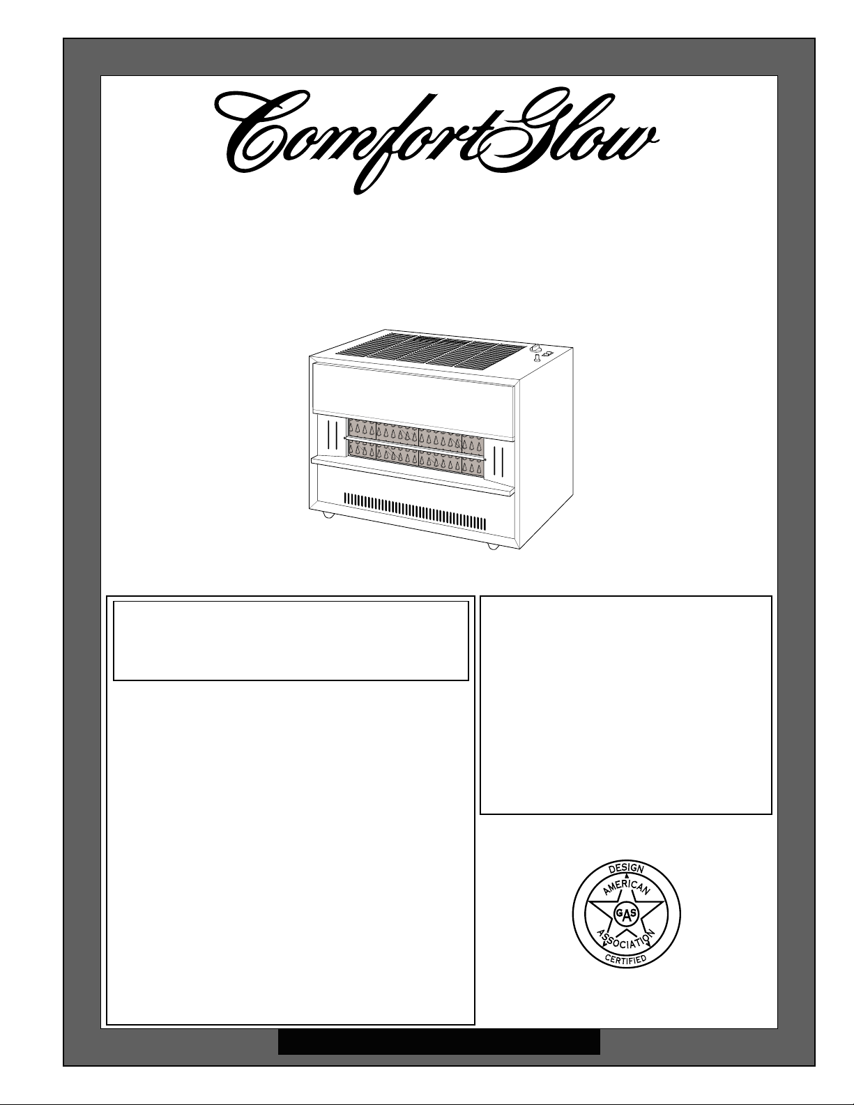
®
VENTED NATURAL
GAS HEATERS
OWNER’S OPERATION AND INSTALLATION MANUAL
Models: CGR65BNA, CGR65NA, CGR50BNA, CGR50NA, CGR35NA
WARNING: If the information in this manual
is not followed exactly, a fire or explosion
may result causing property damage, personal injury, or loss of life.
FOR YOUR SAFETY
— Do not store or use gasoline or other
flammable vapors and liquids in the
vicinity of this or any other appliance.
— WHAT TO DO IF YOU SMELL GAS
• Do not try to light any appliance.
• Do not touch any electrical switch; do
not use any phone in your building.
• Immediately call your gas supplier from
a neighbor’s phone. Follow the gas
supplier’s instructions.
• If you cannot reach your gas supplier,
call the fire department.
— Installation and service must be per-
formed by a qualified installer, service
agency, or the gas supplier.
WARNING: Improper installation,
adjustment, alteration, service, or
maintenance can cause property
damage, personal injury or loss of
life. Refer to this manual for correct installation and operational
procedures. For assistance or
additional information consult a
qualified installer, service agency,
or the gas supplier.
®
Save this manual for future reference.

CONTENTS
SECTION PAGE
Safety Information.........................................................................3
Product Identification .................................................................... 5
Local Codes ................................................................................... 6
Unpacking .................................................................................... 6
Product Features ............................................................................ 6
Installing Heater ............................................................................6
Check Gas Type...................................................................... 6
Installation Items.....................................................................6
Locating Heater.......................................................................7
Venting Heater ........................................................................ 8
Connecting to Gas Supply ...................................................... 11
Checking Gas Connections..................................................... 13
Installing Radiants .................................................................. 14
Installing Glass Panel .............................................................15
Air For Combustion and Ventilation.............................................17
Determining Fresh-Air Flow for Heater Location
Example 1: Locating Heater in Unconfined (Open) Area 18
Draft Hood Spillage Test............................................ 18
Providing Permanent Fresh-Air Ventilation .............. 19
Example 2: Locating Heater in Confined (Closed) Area..20
Ventilating Confined Area ......................................... 20
Operating Heater ........................................................................... 21
For Your Safety Read Before Lighting .................................. 21
Lighting Instructions............................................................... 21
Manual Lighting Procedure .................................................... 23
Blower Operation (For Models with Blower) ........................ 23
To Turn Off Gas To Appliance .............................................. 23
Inspecting Pilot and Burner Flame................................................ 24
Pilot Flame Pattern..................................................................24
Burner Flame Pattern .............................................................. 24
Cleaning and Maintenance ............................................................ 26
Troubleshooting.............................................................................27
Service Procedures ........................................................................32
Removing Control Valve and Burner Tube............................32
Removing Burner.................................................................... 33
Changing Burner Orifice ........................................................ 34
Blower Wiring Diagram................................................................ 34
Technical Service .......................................................................... 35
Specifications ................................................................................ 35
Service Hints ................................................................................. 35
Ordering Replacement Parts..........................................................36
Parts Centrals................................................................................. 36
Accessories .................................................................................... 37
Illustrated Parts List ......................................................................38-41
Warranty Information.................................................................... Back Cover
2
100792
SAFETY
INFORMATION
W ARNINGS
IMPORTANT: Read this owner’s manual carefully and completely be-
fore trying to assemble, operate, or service this heater. Improper use of
this heater can cause serious injury or death from burns, fire, explosion,
electrical shock, and carbon monoxide poisoning.
DANGER
Carbon monoxide poisoning may lead to death!
Carbon Monoxide Poisoning: Early signs of carbon monoxide poisoning
resemble the flu, with headaches, dizziness, or nausea. If you have these signs, the
heater may not be operating or venting properly. Get fresh air at once! Have heater
or heater venting system serviced. Some people are more affected by carbon
monoxide than others. These include pregnant women, people with heart or lung
disease or anemia, those under the influence of alcohol, and those at high altitudes.
Natural Gas: Natural gas is odorless. An odor-making agent is added to natural gas.
The odor helps you detect a natural gas leak. However, the odor added to natural gas
can fade. Natural gas may be present even though no odor exists.
Make certain you read and understand all Warnings. Keep this manual for reference.
It is your guide to safe and proper operation of this heater.
1. A qualified service person must install heater and venting system.
2. Use only natural gas. Do not convert heater to use different fuel type.
3. If you smell gas
• Shut off gas supply.
• Do not try to light any appliance.
• Do not touch any electrical switch; do not use any phone in your building.
• Immediately call your gas supplier from a neighbor’s phone. Follow the gas
supplier’s instructions.
• If you cannot reach your gas supplier, call the fire department.
4. This heater must have fresh air for proper operation. If not, poor fuel combustion
and improper venting of flue gases will result. Carbon monoxide poisoning from
backed-up flue gases could occur. The State of California lists carbon monoxide
as a reproductive toxin under Proposition 65. Read the instructions under
Combustion and Ventilation, pages 17 through 20 for complete information.
5. Never install the heater
• in a mobile home or a recreational vehicle.
• where curtains, furniture, clothing, or other flammable objects are less than 48
inches from the front, 53 inches from top, or 12 inches from right side and 6
inches from left side and back of heater.
• directly on carpeting, tile, or other combustible materials other than wood
flooring. Place heater on metal or wood panel extending the full width and
depth of heater.
• as a fireplace insert.
• in high traffic areas.
• in windy or drafty areas.
Air for
100792
Continued
3
SAFETY
INFORMATION
Continued
W ARNINGS
6. Provide the following minimum heater clearances from combustibles (as viewed
from the front of heater):
Front: 48 inches
Back: 6 inches
Top: 53 inches
Right Side: 12 inches
Left Side: 6 inches
7. Do not run heater
• where flammable liquids or vapors are used or stored
• under dusty conditions
8. Never place clothing or any flammable objects on the heater or venting system.
9. Heater and venting system surfaces are very hot during operation. Keep children
and adults away from hot surfaces to avoid burns or clothing ignition. Carefully
supervise young children when they are in the same room as heater. Heater will
remain hot for a time after shutdown. Let surface cool before touching.
10. Do not use heater as a cooking device.
11. Do not alter heater or its controls. Any change may create a safety hazard.
Continued
12. Turn off heater and unplug (if equipped with blower) and let cool before
servicing. Unless you need gas supply for testing, shut off manual shutoff valve
before servicing. Only a qualified service person should service and repair heater
and venting system.
13. Replace any safety screen or guard removed for servicing before running heater.
14. Do not use heater if any part has been under water. Immediately call a qualified
service person to inspect the heater and to replace any part of the control system and
any gas control which has been under water.
4
100792
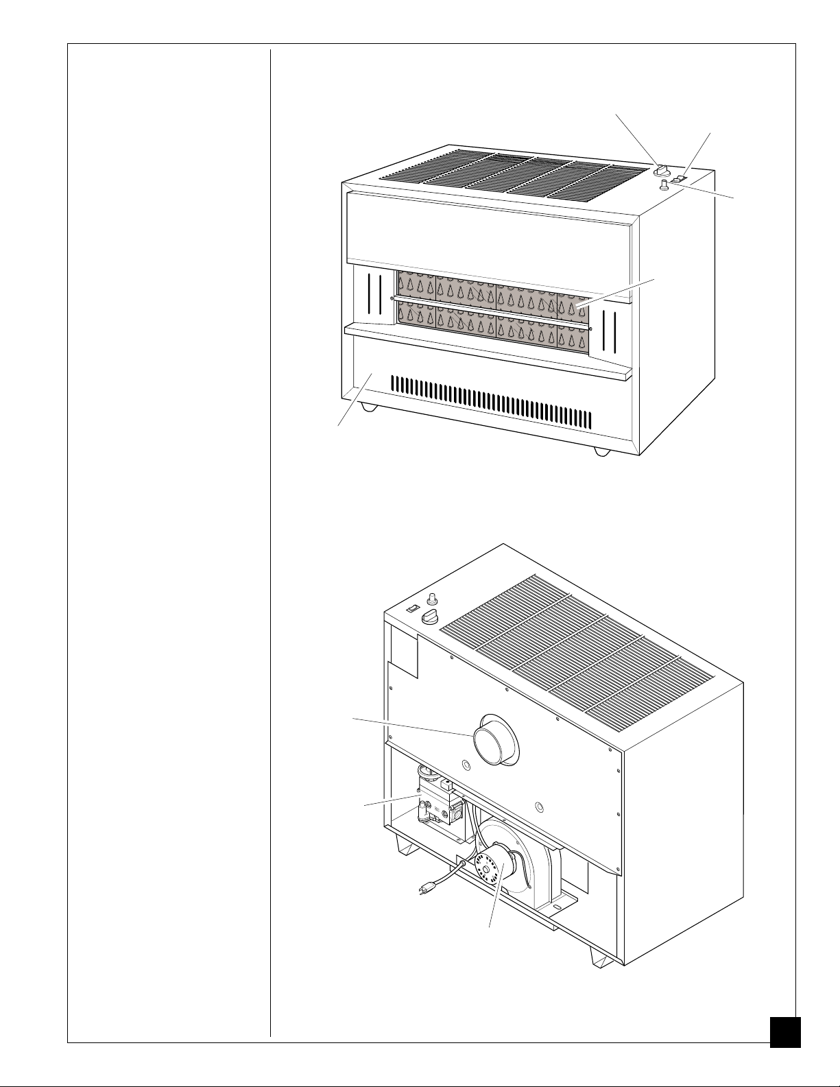
PRODUCT
IDENTIFICATION
Lower Front
Access Panel
Control
Knob
Blower Switch
(on models
equipped with
blower)
Ignitor
Button
Burner
Radiants
Draft Hood
Outlet for
Venting
System
Control
Valve
Figure 1 - Vented Natural Gas Heater
100792
Blower
(on models
equipped with
blower)
Figure 2 - Vented Natural Gas Heater, Rear View
5
LOCAL CODES
Install and use heater with care. Follow all local codes. In the absence of local
codes, use the latest edition of the following:
• National Fuel Gas Code ANSI Z223.1, also known as NFPA 54 *
• National Electrical Code ANSI/NFPA 70 *
*Available from: American National Standards Institute, Inc.
1430 Broadway
New York, NY 10018
National Fire Protection Association, Inc.
Batterymarch Park
Quincy, MA 02269
UNPACKING
PRODUCT
FEATURES
INSTALLING
HEATER
1. Remove heater from carton.
2. Remove all protective packaging applied to heater for shipment.
3. Check heater for any shipping damage. If heater is damaged, promptly inform
dealer where you bought heater.
Piezo Ignition System
This heater has a piezo ignitor. This system requires no matches, batteries, or other
sources to light heater.
Thermostatic Heat Control
This heater has a thermostat sensing bulb and a control valve. This results in the
greatest heating comfort. This can also result in lower gas bills.
W ARNING
A qualified service person must install heater and
venting system. Have them inspect heater before use
and at least annually. Follow all local codes.
NOTICE
This heater must be electrically grounded if equipped with
blower. Follow all local codes. In the absence of local
codes, follow the National Electric Code, ANSI/NFPA 70.
CHECK GAS TYPE
Use only natural gas. If your gas supply is not natural gas, do not install heater.
Call dealer where you bought heater for proper type heater.
INSTALLATION ITEMS
Before installing heater, make sure you have all items below.
• piping (check local codes)
• sealant (resistant to propane gas)
• manual shutoff valve *
• ground joint union
• test gauge connection * (see
Figure 7, page 12)
* An A.G.A. design-certified manual shutoff valve with 1/8" NPT tap is an
acceptable alternative to test gauge connection. Purchase the optional A.G.A.
design-certified manual shutoff valve from your dealer. See Accessories, page 37.
• sediment trap
• tee joint
• pipe wrench
• venting materials
6
100792
INSTALLING
LOCATING HEATER
HEATER
Continued
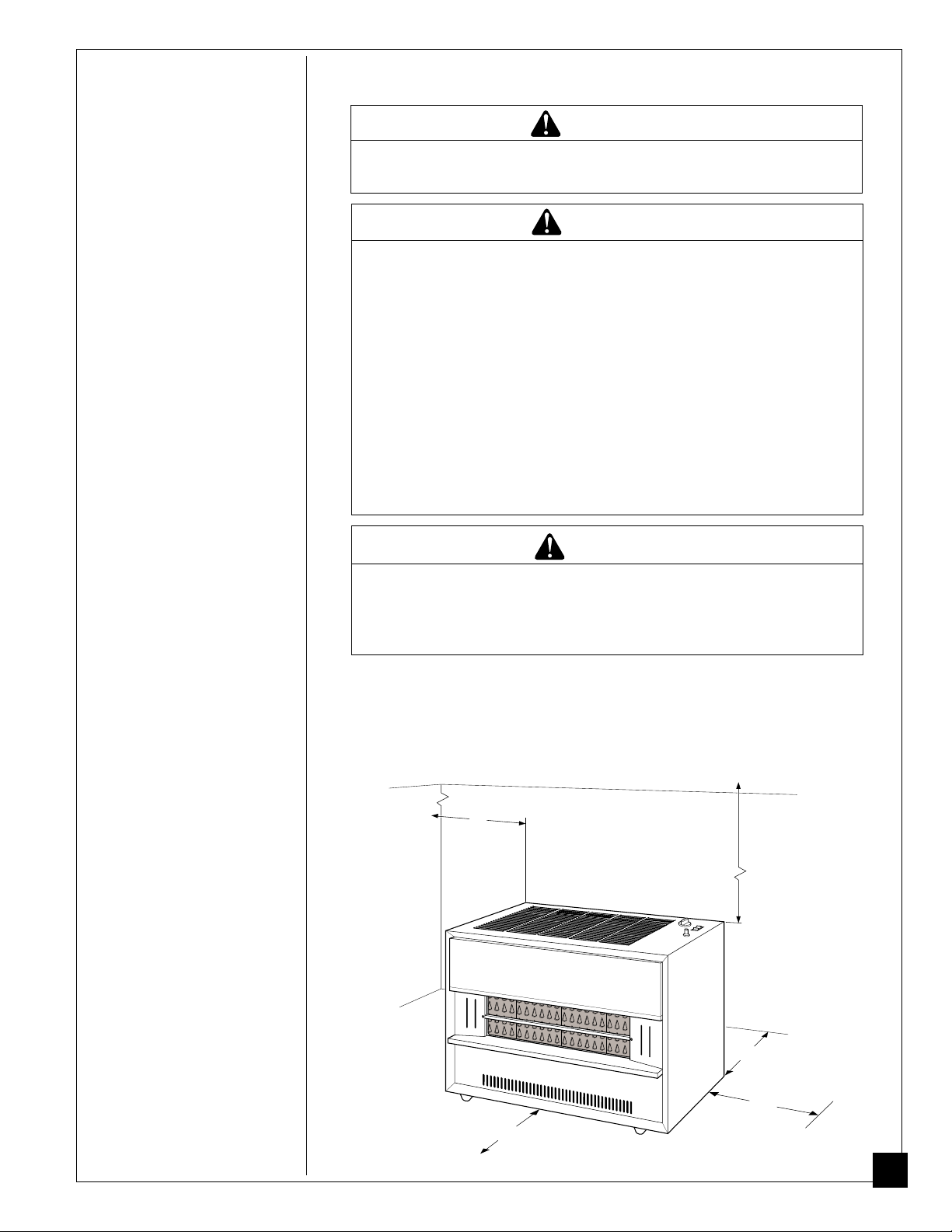
W ARNING
Maintain the minimum clearances shown in Figure 3,
below. If you can, provide greater clearances.
W ARNING
Never install the heater
• in a mobile home or a recreational vehicle.
• where curtains, furniture, clothing, or other flam-
mable objects are less than 48 inches from the front,
53 inches from the top, 12 inches from the right side
and 6 inches from the left side and back of heater.
• directly on carpeting, tile, or other combustible
materials other than wood flooring. Place heater on
metal or wood panel extending the full width and
depth of heater.
• as a fireplace insert.
• in high traffic areas.
• in windy or drafty areas.
CAUTION
If you install the heater in a home garage
• heater pilot and burner must be at least 18 inches
above floor
• locate heater where moving vehicle will not hit it.
100792
For convenience and efficiency, install heater
• where there is easy access for operation, inspection, and service.
• in coldest part of room.
• near an electrical outlet if heater has blower or if you are planning to add
blower to heater. See Accessories, page 37 for blower.
CEILING
6"
Minimum
Left
Side
48" Minimum from
Front of Heater
Figure 3 - Heater Clearances
53"
Minimum
Right
Side
6" Minimum
from Back
12"
Minimum
Continued
7
INSTALLING
HEATER
VENTING HEATER
Note:
Venting/chimney materials are not supplied with heater.
Continued
W ARNING
A qualified service person must install the venting system
for this heater. If venting system is not properly installed
and maintained, the vent safety shut-off system will prevent the heater from running. Follow all local codes.
W ARNING
This heater has a vent safety shut-off system. This
system shuts off the heater gas supply if you do not
vent heater properly or the venting system is blocked.
Do not operate heater if not properly vented. Do not
tamper with the vent safety shut-off system. Carbon
monoxide poisoning and death may result.
W ARNING
When venting this heater, follow the safety information
listed below.
• Never vent heater to another room or inside a building. Only vent heater to the outdoors.
• Do not vent heater exhaust to a chimney or flue
serving another solid-fuel-burning or gas appliance.
• We recommend you use flues classified as prefabricated or masonry all-fuel chimney or type-B vent. See
Vent Types,
• If using old vent, check vent for soot, creosote, and
loose particles. If vent is damaged, repair or replace
it before using heater.
• Extend the vertical section of vent pipe at least three
feet above roof penetration.
• Extend the vertical section of vent pipe at least two
feet above the highest point of any roof within ten
feet.
• The horizontal run of vent pipe should rise at least
1/4 inch for each foot of run.
• Support the vent pipe at least every five feet along its
length. Do not use combustible materials to support
vent pipe.
• Never extend vent pipe horizontally through outside
wall and terminate. You must connect a vertical run
of vent pipe to the horizontal run. The vertical run
must be at least 25% longer than the horizontal run.
• Install vent or chimney cap that is approved for use
with vented gas room heaters.
• Do not use vent pipe smaller in diameter than that of
the heater draft hood outlet.
• Do not use dampers in the vent pipes.
• Vertical height of vent must be greater than five feet
above vent connection at draft hood.
page 10.
8
100792
INSTALLING
VENTING HEATER
(continued)
HEATER
Continued
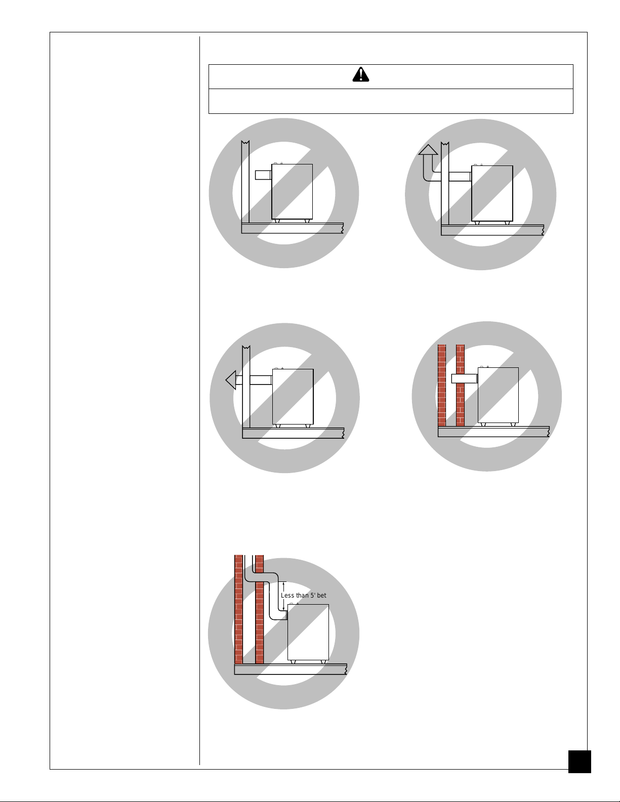
W ARNING
Do not vent heater in any of the following ways (see Figure 4).
Heater must be vented to the outdoors. Never vent heater to another
room or inside a building.
The vertical section of vent pipe must
extend at least two feet above the
highest point of any roof within ten
feet.
100792
Never extend vent pipe horizontally
through outside wall and terminate.
You must connect a vertical run of
vent pipe to the horizontal run. The
vertical run must be at least 25%
longer than the horizontal run.
Less than 5' between elbows
Vertical run of pipe must be at least
five feet from elbow to elbow.
Figure 4 - Improper Venting Systems
Never extend vent pipe horizontally
through a chimney or flue. You must
connect a vertical run of vent pipe to
the horizontal run. The vertical run
must be at least 25% longer or five
feet minimum than the horizontal run.
Continued
9
INSTALLING
HEATER
Continued
VENTING HEATER
(continued)
Proper Size Vent
To safely vent heater, the vent connector pipe must be the same diameter as the draft
hood outlet on the rear of the heater. Pipe that is too small can cause flue gas to spill
from the heater. Fasten vent connector to the draft hood outlet with a sheet metal screw.
Vent Types
Prefabricated or Masonry All-Fuel Chimney - This is a masonry chimney or a
residential-type prefabricated chimney. Only use prefabricated chimneys listed by
Underwriters Laboratories (UL), Inc.
Type-B Vent - These vents are made of noncombustible, corrosion resistant
material. They are certified by a nationally recognized testing agency. Type-B
vents are double-walled pipe. Clearances to combustible construction must be in
accordance with the listing of the particular type-B vent. Type-B vents are currently listed as B-1, B-1 1/2, and B-2.
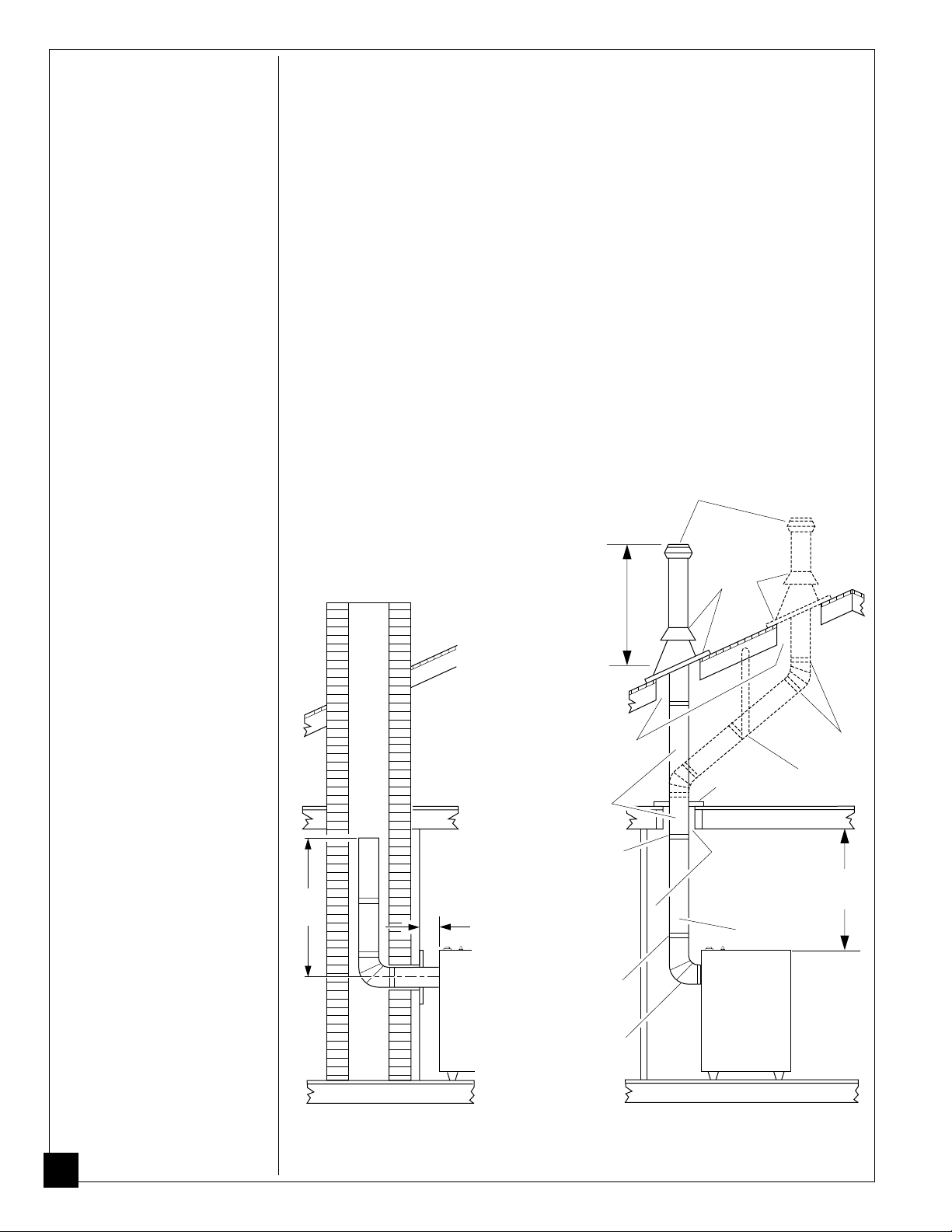
The illustrations below show both vent types. The illustration shows typical
construction of each type of venting system. Minimum clearances and lengths are
added to the illustrations.
Terminate at least 5' above draft hood. If vent extends
over 5' above roof, support with guy wires or braces.
5'
Min.
6"
Min.
Heater
Vent Cap
Must Be At
Least 2 Feet
Above
Highest Point
Within 10
Feet.
Maintain Listed
Clearance of Vent
Support If
Necessary
Lock Joints
Lock Joints
Vent
Connector
Seal Around
Collar and
Flashing
Position
Firestop
Maintain Listed
Clearance of
Vent
Vertical Vent
Heater
Lock
Joints
Support
Laterals
53"
Min.
10
sonry All-Fuel Chimney
Figure 5 - Typical Construction of Venting Systems
Type-B VentPrefabricated or Ma-
Continued
100792
INSTALLING
CONNECTING TO GAS SUPPLY
HEATER
Continued
W ARNING
A qualified service person must connect heater to gas
supply. Follow all local codes.
W ARNING
Never connect heater to private (non-utility) gas wells.
This gas is commonly known as well-head gas.
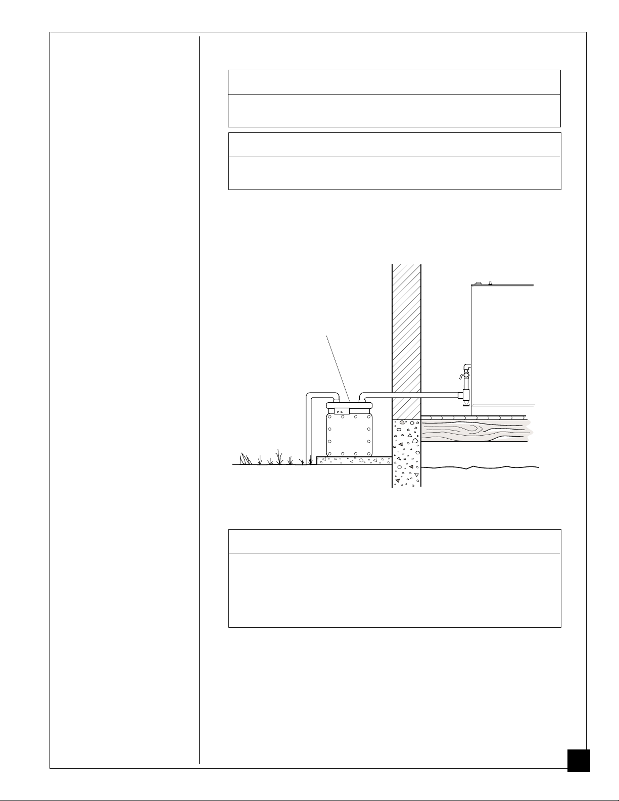
IMPORTANT:
line. Gas line pressure must be no greater than 14 inches of water. If gas line
pressure is higher, heater regulator damage could occur.
Check gas line pressure at gas meter before connecting heater to gas
Gas Meter
100792
Figure 6 - Connecting Heater to Utility Gas Line
CAUTION
Use only new, black iron or steel pipe. Internally-tinned
copper tubing may be used in certain areas. Check your
local codes. Use pipe that is 1/2" in diameter or greater
to allow proper gas volume to heater. If pipe is too
small, undue loss of pressure will occur.
The gas supply line to your heater must be 1/2 inch in diameter or larger. If the
supply line branches to serve two or more heaters, the line from the branch back to
the gas meter must be doubled or tripled, etc., in size (depending upon the number
of heaters).
to serve two heaters, the line diameter from the branch back to the gas meter must
be at least 1 inch. If three heaters are served, the line diameter from the branch
back to the gas meter must be at least 1 1/2 inches.
Note:
Use pipe that is the next size larger than the heater control valve fitting.
Example for 1/2 inch diameter supply line:
If gas supply line total length exceeds forty feet, use a larger diameter pipe.
If the supply line branches
11
INSTALLING
HEATER
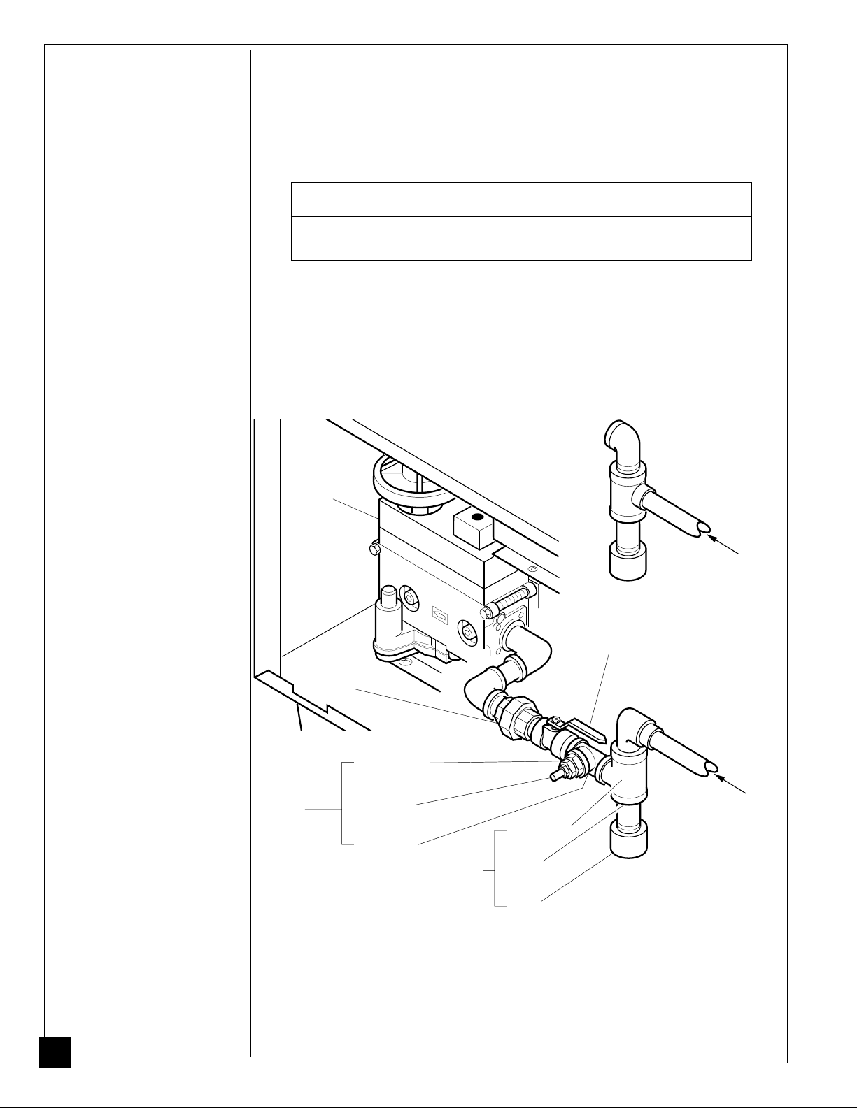
Installation must include a manual shutoff valve, ground joint union, plugged 1/8"
NPT tap, and a sediment trap. Locate NPT tap within reach for test gauge hook up.
NPT tap must be upstream from heater (see Figure 7).
Continued
Apply pipe joint sealant lightly to male threads. This will prevent excess sealant
from going into pipe. Excess sealant in pipe could result in clogged heater valves.
CAUTION
Use pipe joint sealant that is resistant to liquid petroleum (LP) gas.
Install sediment trap in supply line as shown in Figure 7. Locate sediment trap
where it is within reach for cleaning. Locate sediment trap where trapped matter is
not likely to freeze. A sediment trap traps moisture and contaminants. This keeps
them from going into heater controls. If sediment trap is not installed or is installed
wrong, heater may not run properly.
IMPORTANT:
valve of heater. This will prevent turning or damaging control valve.
Control
Valve
Use two pipe wrenches when connecting gas piping to gas control
Acceptable
construction
of inlet gas
line
Ground
Joint
Union
Test
Gauge
Connection*
Reducer
Bushing to
1/8" NPT
1/8" NPT
Plug Tap
Tee Joint
Tee Joint
Sediment
Trap
Figure 7 - Gas Connection
Pipe
Nipple
Cap
Manual
Shutoff
Valve *
From Gas
Meter (5" W.C.
Min** to 7"
W.C. Max)
Preferred
construction
of inlet gas
line
From
Gas
Meter (5"
W.C.
Min** to
7" W.C.
Max)
12
* An A.G.A. design-certified manual shutoff valve with 1/8" NPT tap is an
acceptable alternative to test gauge connection. Purchase the optional A.G.A.
design-certified manual shutoff valve from your dealer. See Accessories, page 37.
** For purposes of input adjustment.
100792
INSTALLING
O
CHECKING GAS CONNECTIONS
HEATER
Continued
W ARNING
Test all gas piping and connections for leaks after installing or servicing. Correct all leaks at once.
WARNING
Never use an open flame to check for a leak. Apply a
mixture of liquid soap and water to all joints. Bubbles
forming show a leak. Correct all leaks at once.
Pressure Testing Gas Supply Piping System
Test Pressures In Excess of 1/2 PSIG
1. Disconnect heater and its individual manual shutoff valve from gas supply
pipe. Pressures in excess of 1/2 PSIG will damage heater regulator.
2. Cap off open end of gas pipe where manual shutoff valve was connected.
3. Pressurize supply piping system by either using compressed air or opening
main gas valve located on or near gas meter.
4. Check all joints of gas supply piping system. Apply mixture of liquid soap and
water to gas joints. Bubbles forming show a leak.
5. Correct all leaks at once.
Test Pressures Equal To or Less Than 1/2 PSIG
1. Close manual shutoff valve (see Figure 8).
2. Pressurize supply piping system by either using compressed air or opening
main gas valve located on or near gas meter.
3. Check all joints from propane supply tank to manual shutoff valve. Apply
mixture of liquid soap and water to gas joints. Bubbles forming show a leak.
4. Correct all leaks at once.
100792
Pressure Testing Heater Gas Connections
1. Open manual shutoff valve (see Figure 8).
2. Open main gas valve located on or near gas meter.
3. Make sure control knob of heater is in the OFF position.
4. Check all joints from manual shutoff valve to control valve on heater. Apply
mixture of liquid soap and water to gas joints. Bubbles forming show a leak.
5. Correct all leaks at once.
6. Light heater (see Operating Heater, pages 21 through 23). Check the rest of the
internal joints for leaks.
7. Turn off heater (see To Turn Off Gas to Appliance,page 23).
On Position
P
Off Position
Figure 8 - Manual Shutoff Valve
Continued
13
INSTALLING
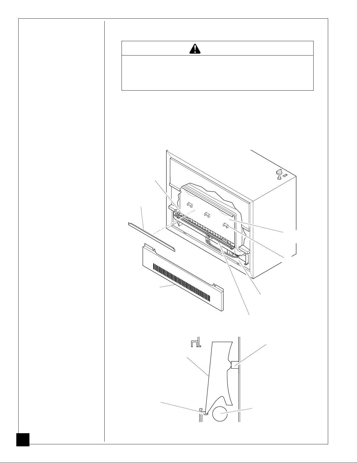
INSTALLING RADIANTS
HEATER
Continued
W ARNING
Carefully handle the glass panel. Glass edges are
rounded and buffed to prevent cuts, however, chipped
or broken sections of glass can present sharp edges.
These sharp edges can cut skin.
1. Remove glass guard from across opening at front of heater (see Figure 8).
2. Place radiants into combustion chamber through opening at front of heater.
Front of radiant sits on front radiant support (see Figure 9, page 14). Back of
radiant rests on back radiant support (see Figures 8 and 9).
Note:
Radiants should never come in contact with burner flame. Contact with
flame may cause carbon or soot deposits on radiants.
Burner
Glass
Guard
Lower
Front Access
Panel
Radiant
Front Radiant
Support
Combustion
Chamber
Back Radiant
Support
Lower Front
Access Area
Glass Retaining Channel
Figure 9 - Location of Radiants
Back Radiant Support
Burner
14
Figure 10 - Position of Radiant
100792

INSTALLING
HEATER
INSTALLING GLASS PANEL
1. Locate the glass panel package inside the back of the heater.
Continued
CAUTION
Before installing glass panels, inspect the edges. If you
notice any chips or cracks, do not install. If the surface on
either side is deeply scratched, do not install. If these
conditions exist, call DESA International’s Technical Service Department at 1-800-323-5190 for replacement glass
panels.
CAUTION
Do not operate heater without glass panels installed.
Operating heater without glass panels will damage front
of heater due to excess temperatures.
CAUTION
Glass panels may have sharp edges. Handle with care.
2. Remove lower front access panel of heater by removing two screws at upper
corners of panel. The lower front access panel covers the lower front access
area (see Figure 9, page 14).
3. Remove two screws on glass guard. Remove glass guard (see Figure 11).
4. Carefully insert one glass panel up through lower front access area (see Figure 11).
5. Carefully slip glass panel behind hearth assembly (see Figure 11).
100792
Screw
Glass
Panel
Glass
Guard
Lower Front
Access Area
Figure 11 - Inserting Glass Panels
Hearth
Assembly
Continued
15

INSTALLING
6. Insert top edge of glass panel into the upper glass retaining channel (see Figure 12).
HEATER
Continued
CAUTION
Make sure you insert top edge of glass panels into the
upper glass retaining channel. Do not install glass
panels with top edge of glass in front of the upper glass
retaining channel. Glass panels will not automatically
go into the channel. You must guide the glass panels
into it. Incorrect installation will damage front of heater
due to excess temperatures.
Upper Glass
Retaining Channel
Lower Glass
Retaining Channel
1
Glass
Panel
2
Lower Front Access Area
Figure 12 - Inserting Top Edge of Glass Panel into
Upper Glass Retaining Channel
7. Lower glass into lower glass retaining channel. Slide glass panel all the way to the
left side.
Note:
If you have chipped or cracked a glass panel during installation, do not
use. Contact DESA International’s Technical Service Department at 1-800323-5190 for a replacement glass panel.
Glass
Panel
Lower Glass
Retaining
Channel
1
2
16
Figure 13 - Inserting Glass into Lower Retaining Channel
8. Repeat steps 4 through 7 for all glass panels.
9. Reinstall glass guard. Reinstall lower front access panel of heater.
100792

AIR FOR
COMBUSTION
AND
VENTILATION
W ARNING
This heater must have fresh air for proper operation. If
not, poor fuel combustion and improper venting of flue
gases will result. Carbon monoxide poisoning from
backed-up flue gases could occur. Read the following
instructions to insure proper fresh air for this and other
fuel-burning appliances in your home.
Today’s homes are built more energy efficient than ever. New materials, increased
insulation, and new construction methods help reduce heat loss in homes. Home
owners weather strip and caulk around windows and doors to keep the cold air out
and the warm air in. During heating months, home owners want their homes as
airtight as possible.
While it is good to make your home energy efficient, it is not good to make it too
airtight. Your home needs to breath. If your home is too airtight, fresh air has little
chance of entering in. This could be dangerous if you have fuel-burning appliances.
These appliances need fresh, outside air for proper combustion and ventilation.
Exhaust fans, fireplaces, clothes dryers, and fuel-burning appliances draw air from
the house to operate. This heater is a fuel-burning appliance. It uses air from inside
the house for combustion. It also uses this air as a draft for venting. This draft air
helps move combustion gases through the vent pipe to the outdoors. If your house
is too airtight, there is not enough fresh air for these items to use. Fresh air may
draw back into the house through venting flues and chimneys. This will keep fuelburning appliances from venting properly. This may cause them to release poisonous carbon monoxide gas into your home. It is very important to provide enough
fresh air to run all fuel-burning appliances.
DANGER
Carbon monoxide poisoning may lead to death!
Carbon monoxide is a colorless, odorless gas. Early signs of carbon monoxide
poisoning resemble the flu, with headaches, dizziness, and/or nausea. If you have
these signs, the heater may not be operating or venting properly. Get fresh air at
once! Have heater or heater venting system serviced. Some people are more
affected by carbon monoxide than others. These include pregnant women, persons
with heart and lung disease and anemia, those under the influence of alcohol, and
those at high altitudes.
Continued
100792
17

AIR FOR
COMBUSTION
AND
VENTILATION
Continued
In the absence of local codes, use the following excerpts from the National Fuel
Gas Code NFPA 54/ANSI Z223.1, Air for Combustion and Ventilation.
DETERMINING FRESH-AIR FLOW FOR HEATER LOCATION
Example 1: Locating Heater in Unconfined (Open) Area
NOTICE
An unconfined area has a minimum air volume of 50
cubic feet for each 1000 BTU/Hr input rating of all
appliances in the area (cubic feet equals length x width
x height of area). Include adjoining rooms only if there
are no doors between the rooms or if you add ventilation grills between the rooms (see
Area,
page 20).
In an open area, the air that leaks around doors and windows may provide enough
fresh air for combustion and ventilation.
Draft Hood Spillage Test
Follow the steps below to see if enough fresh air is available.
1. Close all windows and doors.
2. If you have a fireplace, start a fire. Build fire until flames are burning strongly.
3. Turn on all exhaust fans. These include exhaust fans for kitchen, bathroom,
water heaters (gas or electric), etc.
4. Turn on all vented gas appliances. These include any room heaters, water
heaters, clothes dryer, etc.
5. Wait ten minutes for drafts to regulate.
6. Check for draft-hood spillage at each vented gas appliance. Do this by holding
a lit match two inches from the draft opening (see Figure 14). If match flame
pulls toward the draft hood, there is no spillage. If match flame blows away
from the draft hood, there is spillage. This is a hazardous condition. See Draft
Hood Spillage, page 19.
Ventilating Confined
18
Vent Pipe
Vent Pipe
Draft Hood
Match
Typical
Water
Heater
Figure 14 - Checking for Draft Spillage
No Draft Hood Spillage: This shows there is enough fresh air in area for
Heater
Match
Draft Hood
Opening
appliances. Turn off all exhaust fans and appliances if desired.
100792

AIR FOR
COMBUSTION
Draft Hood Spillage: This is a hazardous situation. Draft hood spillage re-
leases poisonous carbon monoxide gas into your home.
AND
VENTILATION
Continued
DANGER
Carbon monoxide poisoning may lead to death!
If draft hood spillage occurs, check for blocked flue connectors, vent pipes, and
chimneys. If you find blockage, remove. Test again for spillage. If spillage still
occurs or there was no blockage, you need more fresh, outside air in the house. You
must provide additional fresh-air ventilation. Follow the steps below at once.
A. Open a window near the appliance(s) at least two inches. Test again for
spillage. If spillage does not stop, open window more and retest. If spillage
stops, keep window open while running appliance(s). Supply fresh, outside
air by a permanent method as soon as possible. If spillage still occurs, leave
window open and go to next step.
B. If you have a fireplace, open a window or door near it at least two inches.
Test again for spillage. If spillage does not stop, open window or door more
and retest. If spillage stops, keep window or door open while using fireplace. Supply fresh, outside air by a permanent method as soon as possible.
If spillage still occurs, leave window or door open and go to next step.
C. If you have kitchen and bathroom exhaust fans, turn them off. Test again for
spillage. If spillage stops, do not use exhaust fans. Turn off circuit breakers for
fans if possible. Permanently supply fresh, outside air as soon as possible.
Providing Permanent Fresh-Air Ventilation
If draft hood spillage occurs, you must permanently supply fresh, outside air to the
inside of your house. Provide extra fresh air by using ventilation grills or ducts.
Connect these items directly to the outdoors or spaces open to the outdoors. These
spaces include attics and crawl spaces. If you install this heater in an area with
other gas appliances, you must total the BTU/Hr input rating of all appliances.
Follow the National Fuel Gas Code NFPA 54/ANSI Z223.1. It lists fresh-air
requirements for fuel-burning appliances.
100792
IMPORTANT
Do not provide openings for inlet or outlet air into attic
if attic has a thermostat controlled power vent.
Chimney
or Gas
Outlet
Air
Inlet
Air
Vent
Outlet
Air
Inlet Air
Figure 15 - Ventilation Air from Outdoors
Ventilated
Attic
To Attic
To
Crawl
Space
Ventilated
Crawl Space
Continued
19
AIR FOR
Example 2: Locating Heater in Confined (Closed) Area
COMBUSTION
AND
VENTILATION
Continued
NOTICE
A confined area has an air volume of less than 50 cubic
feet for each 1000 BTU/Hr input rating of all appliances
in the area (cubic feet equals length x width x height of
area). Include adjoining rooms only if there are no doors
between the rooms.
If you install this heater in a confined area, you must provide additional fresh air.
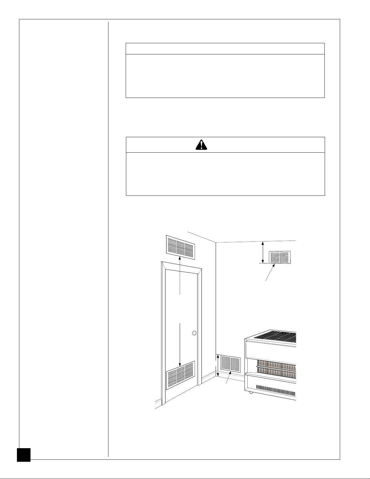
Ventilating Confined Area
This fresh air would come from an adjoining open area or outdoors.
W ARNING
The adjoining open area must have enough fresh,
outside air ventilation to supply any appliance in that
area plus the confined area. Follow instructions under
Example 1: Locating Heater in Unconfined (Open) Area,
page 18 to make sure fresh air ventilation is adequate.
When ventilating to an adjoining open area, you must provide two permanent
openings: one within 12" of the ceiling and one within 12" of the floor on the wall
connecting the two areas. Follow the National Fuel Gas Code NFPA 54/ANSI
Z223.1. It lists fresh-air requirements for fuel-burning appliances.
12"
Ventilation Grills
Connecting Two Rooms
Ventilation
Grills into
Closet for
Hot Water
Heater
Recommended
into Crawl Space in
Furnace Area or in
Closet with Water Heater
Figure 16 - Ventilation Air from Inside Building
to Meet Unconfined Space
12"
Fresh Air Duct
20
After providing ventilation between rooms, check for draft hood spillage (see Draft
Hood Spillage Test, page 18). If draft hood spillage still occurs, provide more
ventilation between rooms or provide permanent ventilation from outdoors. See
Providing Permanent Fresh-Air Ventilation, page 19.
100792

OPERATING
HEATER
W ARNING
Heater and venting system surfaces are very hot during
operation. Keep children and adults away from hot surfaces to avoid burns and clothing ignition. Carefully supervise young children when they are in the same room as
heater. Heater will remain hot for a time after shut down. Let
surface cool before touching.
NOTICE
If operating heater for the first time, a slight odor will occur.
This odor will go away after a few hours of operation.
FOR YOUR SAFETY READ BEFORE LIGHTING
W ARNING
If you do not follow these instructions exactly, a fire or
explosion may result causing property damage, personal injury or loss of life.
A. This appliance has a pilot which must be lighted by hand. When lighting the
pilot, follow these instructions exactly.
B. BEFORE LIGHTING smell all around the appliance area for gas. Be sure to smell
next to the floor because some gas is heavier than air and will settle on the floor.
WHAT TO DO IF YOU SMELL GAS
• Do not try to light any appliance.
• Do not touch any electric switch; do not use any phone in your building.
• Immediately call your gas supplier from a neighbor’s phone. Follow the gas
supplier’s instructions.
• If you cannot reach your gas supplier, call the fire department.
C. Use only your hand to push in or turn the gas control knob. Never use tools. If the
knob will not push in or turn by hand, don’t try to repair it, call a qualified service
technician or gas supplier. Force or attempted repair may result in a fire or explosion.
D. Do not use this appliance if any part has been under water. Immediately call a
qualified service technician to inspect the appliance and to replace any part of the
control system and any gas control which has been under water.
100792
LIGHTING INSTRUCTIONS
1. STOP! Read the safety information above.
2. If heater is equipped with a blower, turn off all electric power to the heater.
3. Make sure manual shutoff valve is fully open.
4. Locate control knob on top of heater. Fully depress control knob in any position
other than PILOT to shut off burner and pilot.
Control Knob
DEPRESS
FOR OFF
LOW
Figure 17 - Control Knob and Ignitor Button
PILOT
HIGH
Ignitor Button
Continued
21
C-clockwise
OPERATING
HEATER
Continued
5. Wait five (5) minutes to clear out any gas. Then smell for gas, including near the
floor. If you smell gas, STOP! Follow “B” in the safety information at the top of
page 21. If you don’t smell gas, go to the next step.
6. Turn control knob clockwise
knob for five seconds.
Note:
You may be running this heater for the first time after hooking up to gas
supply. If so, you may need to depress control knob in for 15 seconds. This
allows air to bleed from the gas system.
7. With control knob depressed, push down and release ignitor button. This will
light pilot. The pilot is attached to the front of burner. You can see pilot through
front glass of heater (see Figure 18). If needed, keep pressing ignitor button until
pilot lights.
Note:
If pilot does not stay lit, refer to Troubleshooting, pages 27 through 31.
Also contact a qualified service person or gas supplier for repairs. Until repairs
are made, light pilot with match. To light pilot with match, see Manual Lighting
Procedure, page 23.
8. Keep control knob depressed for 30 seconds after lighting pilot. After 30 seconds,
release control knob.
• If control knob does not pop up when released, contact a qualified service
person or gas supplier for repairs.
• Shut off gas immediately.
Note:
If pilot goes out, repeat steps 4 through 8.
to the PILOT position. Fully depress control
Clockwise
9. If heater is equipped with a blower, turn on all electrical power to the heater.
10. Turn control knob counterclockwise
11. If equipped, turn blower control to the AUTO or ON position (if desired).
to desired setting.
CAUTION
Do not try to adjust heating levels by using the manual
shutoff valve.
Figure 18 - Viewing Pilot
22
100792

OPERATING
MANUAL LIGHTING PROCEDURE
HEATER
Continued
1. Remove lower front access panel on heater.
2. Locate pilot. Pilot is attached to the front of burner.
3. Follow steps 1 through 6 under Lighting Instructions, pages 21 and 22.
4. With control knob depressed, strike match. Hold match to pilot until pilot lights.
5. Follow steps 8 through 11 under Lighting Instructions, page 22.
BLOWER OPERATION
(For Models with Blower)
W ARNING
This heater has a three-prong, grounded electrical plug.
This plug helps protect you against electrical shock.
Only connect plug to a properly grounded, three-prong
receptacle. Do not cut or remove the grounding prong
from this plug.
1. Plug power cord into a standard 115 volt, 60 hertz outlet.
2. Turn the blower control to either the AUTO or ON position. In the AUTO position,
as the heater begins to heat, the blower will automatically come on. The blower will
remain on until the burner shuts off and cools down. In the ON position, the blower
will stay on constantly. Turn the blower control to the OFF position to stop the
blower at any time.
TO TURN OFF GAS TO APPLIANCE
Shutting Off Heater
1. Fully depress control knob in any position other than PILOT to shut off burner
and pilot.
2. If equipped, turn blower control to OFF position.
Shutting Off Burner Only (pilot stays lit)
1. Turn control knob to the PILOT position. At this setting, only the pilot remains lit.
100792
23

INSPECTING
PILOT AND
BURNER
FLAME
Check pilot flame pattern and burner flame pattern often.
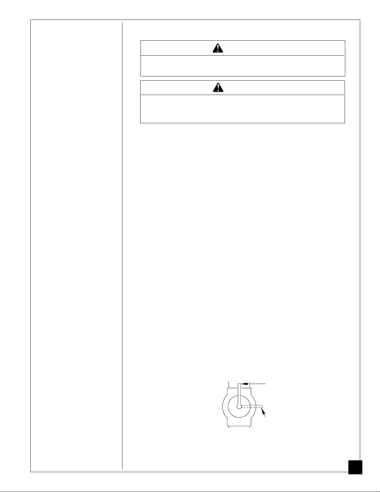
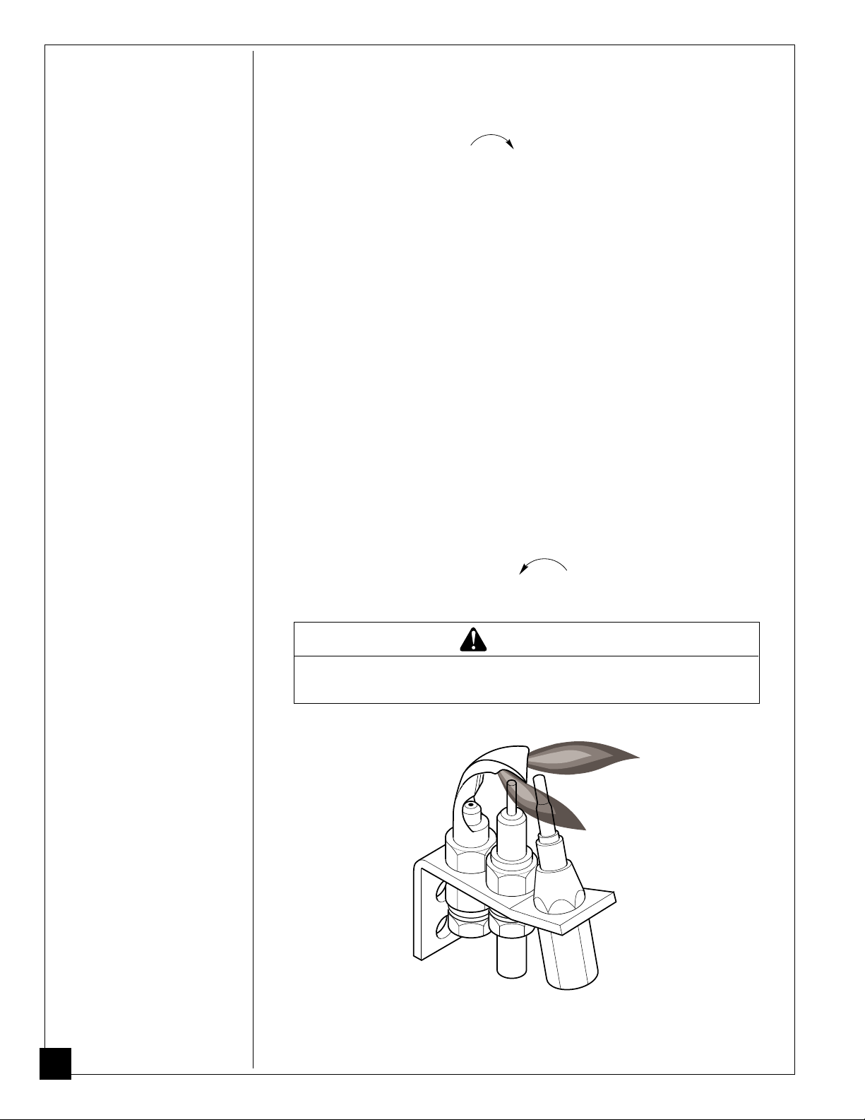
PILOT FLAME PATTERN
Figure 19 shows a correct pilot flame pattern. Figure 20 shows an incorrect pilot
flame pattern. The incorrect pilot flame is not touching the thermocouple. This will
prevent the thermocouple from getting hot, causing the heater to shut down.
Thermocouple
Figure 19 - Correct Pilot
Flame Pattern
If pilot flame pattern is incorrect, as shown in Figure 20
• turn heater off (see To Turn Off Gas to Appliance, page 23)
• contact a qualified service person
Figure 20 - Incorrect
Pilot Flame Pattern
Thermocouple
BURNER FLAME PATTERN
Note:
To view burner flame, look through front glass of heater.
Figure 21, Page 25, shows a correct burner flame pattern. Figure 22, page 25,
shows two incorrect burner flame patterns. The two incorrect flame patterns show
ragged yellow flames and flames lifting off of burner.
W ARNING
If ragged yellow flame occurs, your heater could produce
increased levels of carbon monoxide. If burner flame is
incorrect, follow instructions on page 25.
24
NOTICE
Do not mistake orange flames with yellow flame. Dirt or
other fine dust particles enter the heater and burn
causing brief patches of orange flame.
100792

INSPECTING
PILOT AND
BURNER
FLAME
Continued
Sharp Blue
Flame
Figure 21 - Correct Burner Flame Pattern
Ragged
Yellow
Flame
Flame
Lifting
Off of
Burner
Figure 22 - Incorrect Burner Flame Patterns
If burner flame pattern is incorrect, as shown in Figure 22
• turn heater off (see To Turn Off Gas to Appliance, page 21)
• see Troubleshooting, pages 27 through 31.
100792
25

CLEANING
W ARNING
AND
MAINTENANCE
Turn off heater and let cool before cleaning or servicing.
W ARNING
Keep heater clear and free from combustible materials,
gasoline, and other flammable vapors and liquids.
CAUTION
You must keep control areas, burner, and circulating air
passageways of heater clean. Inspect these areas of
heater before each use. Have heater and venting system
inspected yearly by a qualified service person. Heater
may need more frequent cleaning due to excessive lint
from carpeting, bedding material, etc.
CABINET
Air Passageways
• Use a vacuum cleaner or pressurized air to clean.
Exterior
• Use a soft cloth dampened with a mild soap and water mixture. Wipe the
cabinet to remove dust.
COMBUSTION CHAMBER AND BURNER
Clean the combustion chamber and burner if you have run the heater with a high
yellow flame. Incomplete combustion from lack of air causes the yellow flame.
This will deposit soot inside the combustion chamber and on the burner. To clean
combustion chamber and burner, you must remove the burner from heater. See
Service Procedures, page 33, to remove burner. After removing burner, blow inside
of combustion chamber clean with compressed air. Clean burner with a soft-bristled
brush. Blow soot from burner with compressed air.
PILOT
Use a vacuum cleaner, compressed air, or small, soft-bristled brush to clean.
BURNER ORIFICE
Use a vacuum cleaner, compressed air, or small, soft-bristled brush to clean. You
can also use a tooth pick to clean orifice. Do not enlarge or damage orifice hole.
PILOT AND BURNER FLAME
Check the pilot and burner flame monthly. Make sure pilot and burner flame is
burning correctly. See Inspecting Pilot and Burner Flame, page 24.
VENTING SYSTEM
Check the venting system at least once a year. Make sure joints are secure and vent
pipe is in good condition. Do not obstruct combustion and ventilation air entering
the rear of heater.
26
BLOWER MOTOR (For Models with Blower)
The motor on a new blower is properly lubricated at the factory. The first heating
season, the motor will need no additional care. At the beginning of each season
afterwards, place a few drops of SAE 20 motor oil in the lubrication holes of motor.
Locate the lubrication holes at front and rear of motor on motor casing.
100792

TROUBLE-
W ARNING
SHOOTING
Note: All troubleshooting
items are listed in order of
operation.
Turn off and unplug heater and let cool before servicing.
Unless you need gas supply for testing, shut off manual
shutoff valve before servicing. Only a qualified service
person should service and repair heater and venting
system.
Never use a wire, needle, or similar object to clean pilot.
This can damage pilot.
OBSERVED
PROBLEM
When ignitor button
is pressed, there is no
spark at pilot.
CAUTION
POSSIBLE
CAUSE
1. Incorrect spark gap.
2. Ignitor electrode positioned wrong.
3. Ignitor electrode broken.
4. Ignitor electrode not connected to ignitor cable.
5. Ignitor cable pinched or
wet.
6. Piezo ignitor nut is loose.
7. Broken or frayed ignitor
cable.
8. Loose ignitor cable.
9. Bad piezo ignitor.
REMEDY
1. Adjust spark gap to 1/16".
2. Replace ignitor.
3. Replace ignitor.
4. Reconnect ignitor cable.
5. Free ignitor cable if
pinched by any metal or
tubing. Keep ignitor
cable dry.
6. Tighten nut holding piezo
ignitor to heater cabinet.
Nut is located inside
heater cabinet at top.
7. Replace ignitor cable.
8. Reconnect ignitor cable.
9. Replace piezo ignitor.
100792
When ignitor button
is pressed, there is
spark at pilot but no
ignition.
1. Gas supply turned off or
manual shutoff valve
closed.
2. Control knob not in
PILOT position.
3. Control knob not
pressed in while in
PILOT position.
4. Air in gas lines when
installed.
5. Pilot is clogged.
6. Gas regulator setting is
not correct.
1. Turn on gas supply or
open manual shutoff
valve.
2. Turn control knob to
PILOT position.
3. Press in control knob
while in PILOT position.
4. Continue holding down
control knob. Repeat
igniting operation until
air is removed.
5. Clean pilot (see Clean-
ing and Maintenanc,
page 26) or replace pilot
assembly.
6. Replace control valve.
Continued
27

TROUBLE-
SHOOTING
Continued
OBSERVED
PROBLEM
Pilot lights but flame
goes out when
control knob is
released.
POSSIBLE
CAUSE
1. Manual shutoff valve
not fully open.
2. Control knob not fully
pressed in.
3. Control knob not
pressed in long enough.
4. Safety interlock system
has been triggered.
5. Thermocouple connection loose at control
valve.
6. Pilot flame not touching
thermocouple, which
allows thermocouple to
cool, causing pilot
flame to go out. This
problem could be
caused by any or all of
the following:
A) Improperly adjusted pilot flame
B) Low gas pressure
C) Dirty or partially
clogged pilot
7. Thermocouple damaged.
8. Control valve damaged.
REMEDY
1. Fully open manual
shut-off valve.
2. Press in control knob
fully.
3. After pilot lights, keep
control knob pressed in
30 seconds.
4. Wait one minute for
safety interlock system
to reset. Repeat ignition.
5. Hand tighten until
snug, then tighten 1/4
turn more.
6. A) Contact qualified
service person to
properly adjust pilot
flame.
B) Contact local
natural gas company.
C) Clean pilot
Cleaning and Maintenance, page 26)
replace pilot assembly.
7. Replace thermocouple.
8. Replace control valve.
(see
or
28
Burner does not light
after pilot is lit.
1. Safety interlock
system has been
inadvertently triggered.
2. Burner orifice is
clogged.
3. Burner orifice diameter
is too small.
4. Inlet gas pressure is
too low.
1. Fully depress control
knob in any position
other than pilot. Wait
one minute for safety
interlock system to
reset. Repeat ignition.
2.
Clean burner (see
Cleaning and Maintenance, page 26) or
replace burner orifice
(see Changing Burner
Orifice, page 34.
3. Replace burner orifice
(see Changing Burner
Orifice, page 34).
4. Contact local natural
gas company.
100792

TROUBLE-
SHOOTING
Continued
OBSERVED
PROBLEM
Delayed ignition of
burner.
POSSIBLE
CAUSE
1. Manifold pressure is
too low.
2. Burner orifice is
clogged.
REMEDY
1. Contact local natural gas
company.
2. Clean burner
Cleaning and Maintenance, page 26)
replace burner orifice
(see Changing Burner
Orifice, page 34).
(see
or
Burner backfiring
during combustion.
Yellow flame during
burner combustion.
Flame lifting during
combustion.
1. Burner orifice is
clogged or damaged.
2. Burner damaged.
3. Gas regulator defective.
4. Delayed ignition.
1. Not enough air.
2. Gas regulator defective.
1. Burner orifice clogged
or damaged.
2. Manifold pressure too
high/defective gas
regulator.
1. Clean burner (see
Cleaning and Maintenance, page 26) or
replace burner orifice
(see Changing Burner
Orifice, page 34).
2. Replace burner.
3. Replace control valve.
4. See above.
1. Check burner for dirt
and debris. If found,
clean burner (see
Cleaning and Maintenance, page 26).
2. Replace control valve.
1. Clean burner (see
Cleaning and Maintenance, page 26) or
replace burner orifice
(see Changing Burner
Orifice, page 34).
2. Replace control valve
(see Removing Control
Valve and Burner Tube,
page 32).
100792
Slight smoke or odor
during initial operation.
1. Residues from manufacturing processes.
1. Problem will stop after a
few hours of operation.
Continued
29

TROUBLE-
SHOOTING
Continued
OBSERVED
PROBLEM
Burner fails to
respond to thermostat.
POSSIBLE
CAUSE
1. Pilot flame not lit.
2. Pilot flame not properly heating end of
thermocouple.
3. Pilot burner orifice
clogged or damaged.
4. Control valve defective.
5. Temperature at thermostat bulb satisfied.
REMEDY
1. Light pilot burner (see
Lighting Instructions,
page 32).
2. Pilot flame needs
adjusting. Contact a
qualified service person.
3. Clean pilot burner (see
Cleaning and Maintenance, page 26).
4. Replace control valve.
Heater produces a
whistling noise when
burner is lit.
Heater produces a
clicking/ticking noise
just after burner is lit
or shut off.
1. Air in gas line.
2. Air passageways on
heater blocked.
3. Dirty or partially
clogged burner orifice.
1. Metal expanding while
heating or contracting
while cooling.
1. Operate burner until air
is removed from line.
Have gas line checked
by local natural gas
company.
2. Observe minimum
installation clearances
(see Figure 3, page 7).
3. Clean burner (see
Cleaning and Maintenance, page 26) or
replace burner orifice.
1. This is common with
most heaters. If noise is
excessive, contact
qualified service person.
30
100792

TROUBLE-
SHOOTING
Continued
If you smell gas
• Shut off gas supply.
• Do not try to light any appliance.
• Do not touch any electrical switch; do not
use any phone in your building.
• Immediately call your gas supplier from a
neighbor’s phone. Follow the gas supplier’s
instructions.
• If you cannot reach your gas supplier, call
the fire department.
W ARNING
OBSERVED
PROBLEM
Heater produces
unwanted odors.
Heater shuts off in
use.
POSSIBLE
CAUSE
1. Heater burning vapors
from paint, hair spray,
glues, etc.
2. Gas leak. See Warn-
ing statement at
top of page.
1. Heater not venting
correctly. Vent safety
switch shuts off
heater.
2. Low line pressure.
3. Pilot partially clogged.
REMEDY
1. Ventilate room. Stop
using odor causing
products while heater is
running.
2. Find and correct all
leaks (see Checking Gas
Connections
1. Check venting system.
If damaged or blocked,
repair. If venting
system is OK, have
qualified service person
replace vent safety
switch, wire harness, or
thermocouple interrupter.
2. Contact local natural
gas company.
3. Clean pilot (see Clean-
ing and Maintenance,
page 26).
, page 13).
100792
Gas odor even when
control knob is in
OFF position.
Gas odor during
combustion.
1. Gas leak. See Warn-
ing statement at
top of page.
2. Control valve damaged.
1. Foreign matter between control valve
and burner.
2. Gas leak. See Warn-
ing statement at
top of page.
3. Foreign fumes in area
of heater being drawn
through burner combustion.
1. Find and correct all
leaks (see Checking Gas
Connections
2. Replace control valve.
1. Take apart gas tubing
and remove foreign
matter.
2. Find and correct all
leaks (see Checking Gas
Connections
3. Ventilate area around
heater to remove any
foreign fumes.
, page 13).
, page 13).
31
SERVICE
W ARNING
PROCEDURES
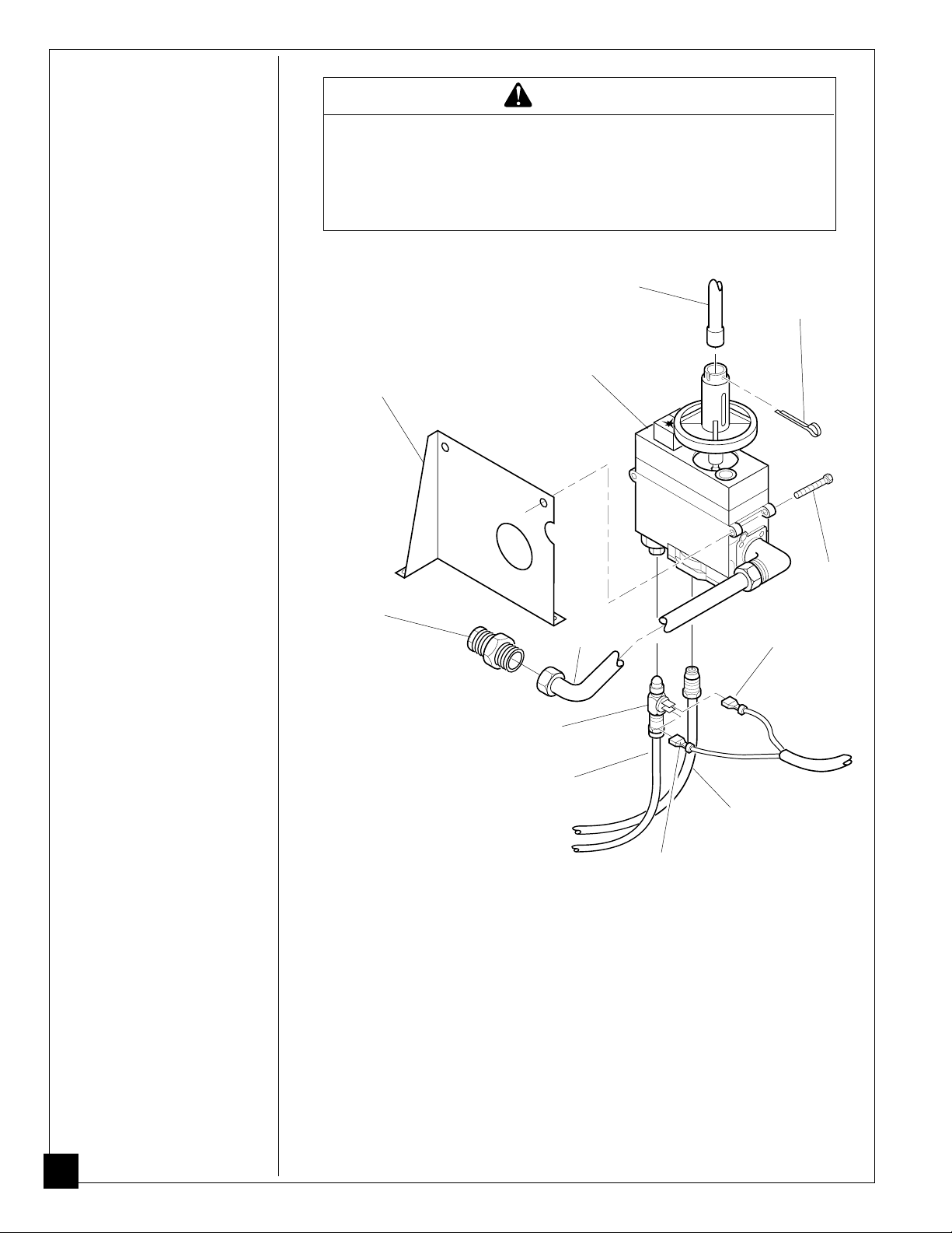
Removing Control Valve
and Burner Tube
1. Shut off gas supply to
heater.
2. Remove lower front
access panel on heater.
3. Disconnect burner tube
from orifice holder (see
Figure 23).
4. Remove pilot gas line
from control valve (see
Figure 23).
5. Disconnect wire connectors from thermocouple
interrupter (see Figure
23).
6. Remove thermocouple
and thermocouple interrupter from control valve.
7. Remove cotter pin from
control valve. This
releases the control rod
from valve (see Figure
23).
8. Remove the two mounting
screws from control valve
mounting bracket (see
Figure 23).
9. Remove assembly from
the rear of heater.
10.To reinstall, reverse above
steps. Turn on gas to
heater and check for gas
leaks. Apply a mixture of
liquid soap and water to
all joints. Bubbles forming
show a leak. Correct all
leaks at once.
11.Replace lower front
access panel.
Turn off and unplug heater and let cool before servicing.
Unless you need gas supply for testing, shut off manual
shutoff valve before servicing. Only a qualified service
person should service and repair heater and venting
system.
Control Rod
Control Valve
Bracket
Orifice
Holder
Figure 23 - Removing Control Valve and Burner Tube
Control Valve
Thermocouple
Interrupter
Thermocouple
Burner
Tube
Wire Connector
Pilot Gas Line
Wire Connector
Cotter Pin
Mounting
Screw
32
100792

SERVICE
PROCEDURES
Continued
Removing Burner
1. Shut off gas supply to
heater.
2. Remove lower front
access panel on heater.
3. Disconnect burner tube
from orifice holder (see
Figure 24).
4. Remove orifice holder
from burner (see Figure
24).
5. Remove pilot burner
bracket nuts and remove
pilot assembly (see Figure
24).
6. Move burner to the right
for clearance. Rotate
burner 90° and remove
burner through lower front
access opening.
7. To reinstall, reverse above
steps. Turn on gas to
heater and check for gas
leaks. Apply a mixture of
liquid soap and water to
all joints. Bubbles forming show a leak. Correct
all leaks at once.
8. Replace lower front
access panel.
Burner
Burner
Tube
Pilot Burner
Bracket Nut
Figure 24 - Removing Burner Tube, Orifice Holder, and Pilot Burner Assembly
Pilot Burner
Assembly
Orifice
Holder
(35,000 BTU/Hr Burner Shown)
Continued
100792
33

SERVICE
PROCEDURES
Continued
Changing Burner Orifice
1. Shut off gas supply to
heater.
2. Remove lower front
access panel on heater.
3. Disconnect burner tube
from orifice holder (see
Figure 25).
4. Remove orifice holder
from burner (see Figure
25).
5. Use socket or open-end
wrench to remove the old
orifice from the orifice
holder.
6. Clean and replace orifice,
or replace with new
orifice.
7. Turn on gas to heater and
check for gas leaks. Apply
a mixture of liquid soap
and water to all joints.
Bubbles forming show a
leak. Correct all leaks at
once.
8. Replace lower front
access panel.
Burner
Orifice
Burner
Tube
Orifice
Holder
Figure 25 - Orifice Location (35,000 BTU/Hr Burner Shown)
Figure 26 - Orifice
34
BLOWER
WIRING
DIAGRAM
(For Models With
Blower Assembly)
110/115 V.A.C.
Fan Switch
(Off/On/Auto)
Off
Black Blue
Black
White
Green
On
Auto
Red
Fan
Switch
(N.O.)
Black
Blower
Motor
Red
White
100792

TECHNICAL
SERVICE
You may have further questions about installation, operation, or troubleshooting.
If so, contact DESA International’s Technical Service Department at 1-800-323-
5190.
SPECIFICATIONS
35,000 BTU/Hr 50,000 BTU/Hr 65,000 BTU/Hr
Model Model Model
BTU 35,000 50,000 65,000
Type Gas Natural Only Natural Only Natural Only
Ignition Piezo Piezo Piezo
Pressure Regulator Setting 3.5" W.C. 3.5" W.C. 3.5" W.C.
Inlet Gas Pressure
Maximum 7" W.C. 7" W.C. 7" W.C.
Minimum 5" W.C. 5" W.C. 5" W.C.
Dimensions, Inches
Heater (H x W x D) 25 x 27
Shipping Weight (pounds) 97 133**/120 158**/145
Flue Vent Size 4" dia. 4" dia. 5" dia.
Orifice Size 34 drill, ø .111 29 drill, ø .136 3.8 mm, ø .1496
** When equipped with blower
Note:
These heaters are certified for elevations of 0-4500 feet above sea level. For
elevations above 2000 feet, de-rate heater 4% for each 1000 feet above sea level.
1
/4 x 16 28 x 32 1/2 x 16 31 x 37 3/4 x 16
SERVICE
HINTS
When gas pressure is too low
• pilot will not stay lit
• burner will have delayed ignition
• heater will not produce specified heat
When gas quality is bad
• pilot will not stay lit
• burner will produce yellow flames and soot
• heater will backfire when lit
You may feel your gas pressure is too low or gas quality is bad. If so, contact your
local natural gas supplier.
100792
35

ORDERING
REPLACEMENT
PARTS
Note:
Use only original replacement parts. This will protect your warranty cover-
age for parts replaced under warranty.
Parts Under Warranty
Contact your nearest dealer or call DESA International’s Technical Service Department at 1-800-323-5190.
When calling DESA International, have ready
• your name
• your address
• model number of your heater
• how heater was malfunctioning
• type of gas used (propane or natural gas)
• purchase date
Usually, we will ask you to return the defective part to the factory.
Parts Not Under Warranty
Contact your nearest dealer. If they can’t supply original replacement part(s),
either contact your nearest Parts Central (below) or call DESA International’s Parts
Department at 1-800-972-7879 for information.
When calling DESA International, have ready
• model number of your heater
• the replacement part number
36
PARTS
CENTRALS
These Parts Centrals are privately owned businesses. They have agreed to support
our customer’s needs by providing original replacement parts and accessories. For
certain parts, some Parts Centrals may refer you to a dealer in your area. When
calling a Parts Central, ask for the Parts Department.
Howard Industries
1514 South Maple Ave.
Los Angeles, CA 90015
213-747-5121
Victor Manufacturing
42 Rumsey Road
E. Hartford, CT 06108
NY, NJ, DE, PA, MD
203-289-4223
Controlled Engineering
299 Roosevelt Road
Glen Ellyn, IL 60137
708-469-7300
Portable Heater Parts
342 N. Country Rd. 400E
Valparaiso, IN 46383
All States
219-462-7441
1-800-362-6951
FBD
601 Hope Street
Bowling Green, KY 42101
502-796-8406
1-800-654-8534
American Air Dist.
537 W. 62nd Street
Shreveport, LA 71108
318-861-0634
Master Service Center
1184 Wilson
Grand Rapids, MI 49504
616-791-4760
1-800-446-1446
Washer Equipment Co.
1715 Main Street
Kansas City, MO 64108
KS, MO, AR
816-842-3911
Controls, Inc.
6820 Glenwood Ave.
Raleigh, NC 27612
NC, SC, VA, MD
919-787-2242
1-800-334-5886
Taratin Tank Co.
P.O. Box 6129
Freehold, NJ 07728
908-780-9340
East Coast Energy
833 Broadway
W. Long Branch, NJ 07764
908-870-8809
1-800-755-8809
ATP Services
990 Avenue of Americas
New York, NY 10018
212-967-6255
Dayton Hardware
P. O. Box 275
North Dayton Station
Dayton, OH 45404
All States
513-258-3721
OH only 1-800-762-3426
Central Air Supply
424 North Rockwell
Oklahoma City, OK 73127
405-495-0014
Warmer Image
208 Carter Drive, Unit 21
West Chester, PA 19382
215-696-2670
1-800-368-0803
LaPorte’s Parts & Service
2444 North 5th Street
Hartsville, SC 29550
803-879-3009
Parts Department
Cans Unlimited, Inc.
P. O. Box 645
Taylor, SC 29687
All States
803-879-3009
1-800-845-5301
Dealers LP Equip. Co.
P.O. Box 341145
Bartlett, TN 38184
AL, TN
901-386-8780
Capitol Hydronic Supply
104 West Jefferson Street
Falls Church, VA 22046
703-532-1622
Tuco Industrial Products
P.O. Box 5076
Lynwood, WA 98046
206-743-9533
1-800-735-1268
Auer Steel Supply
2935 W. Silver Spring Dr.
Milwaukee, WI 53209
414-463-1234
100792

ACCESSORIES
Purchase these heater accessories from your local dealer. If they can not supply
these accessories, contact your nearest Parts Central (see page 36). You can also
write to the address listed on the back page of this manual for information.
BLOWER KIT - PART NUMBER GA6010
For all models. Provides better heat distribution.
Makes heater more efficient. Complete installation
and operating instructions provided with blower.
100792
MANUAL SHUTOFF
VALVE - GA5010
For all models. Manual shutoff valve
with 1/8" NPT tap.
37

ILLUSTRATED
P ARTS LIST
Blower
This list contains replaceable parts used in your heater. When ordering parts, follow the
instructions listed under Ordering Replacement Parts on page 36 of this manual.
Assembly
1
2
9
3
4
8
5
7
PART NUMBER FOR
KEY
NO. CGR65BNA CGR65NA CGR50BNA CGR50NA CGR35NA DESCRIPTION QTY.
1 099998-01 —— 099998-01 —— —— Fan Switch 1
2 100045-01 —— 100045-01 —— —— Wire Harness 1
3 100042-01 —— 100042-01 —— —— Fan Limit Switch 1
4 M11084-38 —— M11084-38 —— —— Screw, #8-18 x 3/8" 2
5 100121-01 —— 100121-01 —— —— Blower 1
6 M11084-26 —— M11084-26 —— —— Screw, #10-16 x 3/8" 6
7 531001 —— 531001 —— —— Blower Pan 1
8 098304-01 —— 098304-01 —— —— Screw, #10-24 x 3/8" 1
9 099123-01 —— 099123-01 —— —— Thermobulb Clip 1
6
38
100792

ILLUSTRATED
P ARTS LIST
Cabinet
Assembly
4
3
This list contains replaceable parts used in your heater. When ordering parts, follow the
instructions listed under Ordering Replacement Parts on page 36 of this manual.
6
10
8
11
7
9
6
5
2
1
KEY
NO. CGR65BNA CGR65NA CGR50BNA CGR50NA CGR35NA DESCRIPTION QTY.
1 100202-03 100202-03 100202-02 100202-02 100202-01 Lower Front Panel 1
2 098304-01 098304-01 098304-01 098304-01 098304-01 Screw, #10-16 x 3/8" 2
3 100053-03BS 100053-03BS 100053-02BS 100053-02BS 100053-01BS Hearth Assembly 1
4 100204-03 100204-03 100204-02 100204-02 100204-01 Top Panel 1
5 098304-02 098304-02 098304-02 098304-02 098304-02 Screw, #6-20 x 3/8" 2
6 M11084-26 M11084-26 M11084-26 M11084-26 —— Screw, #10-16 x 3/8" 17
—— —— —— —— M11084-26 Screw, #10-16 x 3/8" 19
7 100205-03BS 100205-03BS 100205-02BS 100205-02BS 100205-01BS Glass Guard 1
8 100203-03 100203-03 100203-02 100203-02 100203-01 Cabinet Assembly 1
9 099123-01 099123-01 099123-01 099123-01 099123-01 Thermobulb Clip 2
10 100101-03BS 100101-03BS 100101-02BS 100101-02BS 100101-01BS Cabinet Back 1
11 —— 099997-01 —— 099997-01 099997-01 Switch Plug 1
099988-02 099988-02 099988-02 099988-02 099988-02 Lighting Instructions
099987-02 099987-02 099987-02 099987-02 099987-02 Control Position Decal 1
100154-02 100154-02 100154-02 100154-02 100154-02 Warning Decal 1
6
PART NUMBER FOR
(includes items 5 & 7)
PARTS AVAILABLE - NOT SHOWN
Decal 1
100792
39

ILLUSTRATED
P ARTS LIST
Burner
Assembly
1
3
2
4
26
27
23
25
16
50 and 65
Models
29
7
28
5
22
7
24
30
31
21
20
4
19
18
13
15
10
9
16
17
11
35 Model
Only
11
12
14
6
7
6
8
40
100792

P ARTS LIST
This list contains replaceable parts used in your heater. When ordering parts, follow the
instructions listed under Ordering Replacement Parts on page 36 of this manual.
Burner
Assembly
PART NUMBER FOR
KEY
NO. CGR65BNA CGR65NA CGR50BNA CGR50NA CGR35NA DESCRIPTION QTY.
1 100729-03 100729-03 100729-02 100729-02 100729-01 Combustion Chamber 1
2 098324-02 098324-02 098324-02 098324-02 098324-02 Control Knob 1
3 097159-02 097159-02 097159-02 097159-02 097159-02 Piezo Ignitor 1
4 098271-05 098271-05 098271-05 098271-05 098271-05 Ignitor Cable 1
5 099974-03 099974-03 099974-02 099974-02 099974-01 Control Rod 1
6 063017 063017 100481-01 100481-01 063015 Limit Switch Bracket 1
7 M11084-26 M11084-26 —— —— M11084-26 Screw, #10-16 x 3/8" 6
—— —— M11084-26 M11084-26 —— Screw, #10-16 x 3/8" 5
8 099986-02 099986-02 099986-01 099986-01 099986-01 Wire Assembly 1
9 100000-01 100000-01 100000-01 100000-01 100000-01 Cotter Pin 1
10 231939 231939 231939 231939 231940 Limit Switch 1
11 M11084-38 M11084-38 M11084-38 M11084-38 —— Screw, #8-18 x 3/8" 3
—— —— —— —— M11084-38 Screw, #8-18 x 3/8" 2
12 099211-01 099211-01 099211-01 099211-01 099211-01 Screw, #10-16 x 2 1/4" 2
13 100207-01 100207-01 100207-01 100207-01 100207-01 Control Valve 1
14 098265-01 098265-01 098265-01 098265-01 098265-01 Elbow 1
15 098936-02 098936-02 098936-02 098936-02 098936-02
16 100028-02 100028-02 100028-02 100028-02 100028-02 Pilot Tubing 1
17 100307-01 100307-01 100307-01 100307-01 100307-01 Thermocouple 1
18 171176 171176 171176 171176 171176 Burner Tube 1
19 530988 530988 530988 530988 530988 Control Bracket 1
20 100309-01 100309-01 100309-01 100309-01 100309-01 Orifice Holder 1
21 180257 180257 180245 180245 180233 Orifice 1
22 100706-01 100706-01 100385-01 100385-01 100384-01 Burner Assembly 1
23 100310-01 100310-01 100310-01 100310-01 100310-01 Pilot Mounting Bracket 2
24 100308-01 100308-01 100308-01 100308-01 100308-01 Pilot (Includes 30 & 31) 1
25 M12461-25 M12461-25 M12461-25 M12461-25 M12461-25 Screw, 10-32 x 1/4" 2
26 098249-01 098249-01 098249-01 098249-01 098249-01 Nut, M5 x 0.8 2
27 101342-03 101342-03 101342-02 101342-02 101342-01 Glass Panel Package
28 100772-01 100772-01 —— —— —— Radiant 5
—— —— 100772-01 100772-01 —— Radiant 4
—— —— —— —— 100772-01 Radiant 3
29 530192 530192 530192 530192 530192 Glass Spring 2
30 100468-01 100468-01 100468-01 100468-01 100468-01 Pilot Electrode 1
31 100465-01 100465-01 100465-01 100465-01 100465-01 Electrode Nut 1
Thermocouple Interrupter
(Includes Retainer) 1
1
100792
41

NOTES
_________________________________________________________________
_________________________________________________________________
_________________________________________________________________
_________________________________________________________________
_________________________________________________________________
_________________________________________________________________
_________________________________________________________________
_________________________________________________________________
_________________________________________________________________
_________________________________________________________________
_________________________________________________________________
_________________________________________________________________
_________________________________________________________________
_________________________________________________________________
_________________________________________________________________
_________________________________________________________________
_________________________________________________________________
_________________________________________________________________
_________________________________________________________________
_________________________________________________________________
_________________________________________________________________
_________________________________________________________________
_________________________________________________________________
_________________________________________________________________
_________________________________________________________________
_________________________________________________________________
_________________________________________________________________
_________________________________________________________________
_________________________________________________________________
_________________________________________________________________
_________________________________________________________________
_________________________________________________________________
_________________________________________________________________
_________________________________________________________________
42
_________________________________________________________________
_________________________________________________________________
_________________________________________________________________
_________________________________________________________________
_________________________________________________________________
100792

NOTES
_________________________________________________________________
_________________________________________________________________
_________________________________________________________________
_________________________________________________________________
_________________________________________________________________
_________________________________________________________________
_________________________________________________________________
_________________________________________________________________
_________________________________________________________________
_________________________________________________________________
_________________________________________________________________
_________________________________________________________________
_________________________________________________________________
_________________________________________________________________
_________________________________________________________________
_________________________________________________________________
_________________________________________________________________
_________________________________________________________________
_________________________________________________________________
_________________________________________________________________
_________________________________________________________________
_________________________________________________________________
_________________________________________________________________
_________________________________________________________________
_________________________________________________________________
_________________________________________________________________
_________________________________________________________________
_________________________________________________________________
_________________________________________________________________
_________________________________________________________________
_________________________________________________________________
_________________________________________________________________
_________________________________________________________________
_________________________________________________________________
100792
_________________________________________________________________
_________________________________________________________________
_________________________________________________________________
_________________________________________________________________
_________________________________________________________________
43

WARRANTY INFORMATION
Always specify model and serial numbers when communicating with the factory.
We reserve the right to amend these specifications at any time without notice. The only warranty applicable is our standard written
warranty. We make no other warranty, expressed or implied.
LIMITED WARRANTY
COMFORT GLOW VENTED NATURAL GAS HEATERS
LIMITED ONE YEAR WARRANTY
This DESA product is warranted to the original purchaser to be free from defect in material and workmanship under normal use and
maintenance for a period of one year from the date of installation whether or not actual use begins on that date. It is the responsibility
of the consumer/owner to establish the warranty period. You are required to furnish proof of installation date, which may be a Bill of
Sales or other payment record which verifies the original installation. A new or remanufactured part to replace any defective part will
be provided, at DESA’s sole option, without charge for the part itself, FOB the shipping point. The exchanged part will be warranted
for only the unexpired portion of the original warranty. Defective parts must be returned to DESA, transportation charges prepaid,
(DESA is not responsible for any freight charges), where DESA will establish to its sole satisfaction that the part was or became
defective under normal use and maintenance. No reimbursement will be made for transportation, diagnostics, shipping, handling, or
other incidental expenses. This warranty applies only to the product in its original installation location and is voided if the product is
reinstalled elsewhere.
LIMITED FOUR YEAR WARRANTY ON COMBUSTION CHAMBER
During the second through fifth years after the date of original installation, DESA further warrants the combustion chamber against
defects in material and workmanship under normal use and maintenance. A replacement combustion chamber will be provided under
the same conditions as stated in the one year warranty.
LIMITATION OF WARRANTIES
All implied warranties (including implied warranties of merchantability) are hereby limited in duration to the period for which each
limited warranty is given. Some states do not allow limitations on how long an implied warranty lasts so the above limitations may
not apply to you. The expressed warranties made in this warranty are exclusive and may not be altered, enlarged, or changed by any
distributor, dealer, or other person whomsoever.
DESA WILL NOT BE RESPONSIBLE FOR:
1. Normal maintenance as outlined in the owner’s operation and installation manual including cleaning of component parts; such as,
orifices and burners.
2. Failure to start and/or operate due to voltage or gas condition, blown fuses, open circuit breakers, loose or disconnected wires, low
gas pressure, or other damages due to inadequacy or interruption of electrical service or gas supply.
3. Damage or repairs required as a consequence of faulty or incorrect installation not in conformance with DESA instructions.
4. Damage as a result of floods, winds, lightning, accidents, corrosive atmosphere, or other conditions beyond the control of DESA.
5. Parts or accessories not supplied by DESA.
6. Costs incurred in gaining access to the heater.
7. Damage or repairs needed as a consequence of any misapplication, abuse, unreasonable use, unauthorized alteration, improper
servicing, improper operation, or failure to provide reasonable and necessary maintenance.
8. Freight charges incurred from parts replacement.
9. DESA product installed outside the Continental U.S.A. and Alaska.
10. DESA products whose serial number has been altered, defaced, or removed.
11. Fuel or electricity costs or increases in such costs from any reason whatsoever.
12. Any special, indirect or consequential property, economic, or commercial damage of any nature whatsoever. Some states do not
allow the exclusion of incidental or consequential damages, so the above limitation may not apply to you.
No representative, dealer, or other person is authorized to assume for DESA International any additional, different, or other liability
in connection with the sale of this DESA product.
This warranty gives you specific legal rights, and you may also have other rights which vary from state to state.
For more information about this warranty, write:
2701 Industrial Drive
P.O. Box 90004
Bowling Green, KY 42102-9004
100792-01
REV. C
11/94
 Loading...