


Desa C36EMW User Manual

r
r
A
I
INSTALLATION INSTRUCTIONS
This book is valuable. In addition to instructing you on
how to install and maintain your appliance, it also
contains information that will enable you to obtain
replacement parts or accessory items when needed.
Keep it with your other important papers.
SAVE THIS BOOK
WARNING: Always leave glass doors fully opened or fully closed when operating this fireplace.
This firebox meets the construction and safety standards of H.U.D. fo
application in mobile homes when installed according to these instructions.
Includes: Manual Variable Control Fan System, Combustion
Air Kit and Bi-Fold Doors with Brushed Brass Finish
This fireplace is approved for use as a wood burning fireplace or fo
use with a vented gas log approved to ANS Z21.60, Z21.84 or RGA
2-72 standards or
ANS Z21.11.2 standard. A DESA hood must be installed when
using a vent-free gas log heater (see Accessories, p. 12).
C36EMW
36” Circulating Firebox
for use with a vent-free gas log heater approved to
LL DIMENSIONS IN THIS MANUAL ARE IN
NCHES UNLESS OTHERWISE SPECIFIED
DESA INTERNATIONAL
2701 INDUSTRIAL DRIVE P/N 108771-01
P.O. BOX 90024 REV D
BOWLING GREEN, KY 42101-9004 6/02
www.desatech.com

CONTENTS
1. INTRODUCTION ------------------------------------------------------------- PG. 2
2. SELECTING LOCATION ------------------------------------------------------------- PG. 2
3. MINIMUM CLEARANCES ------------------------------------------------------------- PG. 2
4. FRAMING AND INSTALLING ------------------------------------------------------------- PG. 3
5. HEARTH EXTENSION ------------------------------------------------------------- PG. 3
6. OUTSIDE AIR KIT INSTALLATION ------------------------------------------------------------- PG. 4
7. FAN KIT ASSEMBLY ------------------------------------------------------------- PG. 4
8. CHIMNEY PIPE ------------------------------------------------------------- PG. 4-5
9. FIRESTOP THIMBLE AND SPACERS ------------------------------------------------------------- PG. 5-6
10. FLASHING AND TERMINATION ------------------------------------------------------------- PG. 7
11. FINISHING YOUR FIREPLACE ------------------------------------------------------------- PG. 8
12. MANTEL ------------------------------------------------------------- PG. 8
13. GLASS DOORS ------------------------------------------------------------- PG. 8
14. GAS LINE INSTALLATIONS ------------------------------------------------------------- PG. 9
15. OUTSIDE AIR AND DAMPER HANDLE ------------------------------------------------------------- PG. 10
LOCATION
16. TECHNICAL SERVICE ------------------------------------------------------------- PG. 10
17. ILLUSTRATED PARTS ------------------------------------------------------------- PG.11-11a
18. REPLACEMENT AND TECHNICAL PARTS ------------------------------------------------------------- PG.12
19. PART NUMBER REFERENCE TABLE ------------------------------------------------------------- PG.12a
- 1 - For more information, visit www.desatech.com
r
d
n
jury
y
l
y
b
r
• Do not store or use gasoline or any other flammable
vapors or liquids in the vicinity of this or any othe
appliance.
• Due to high temperatures, the appliance should be
located out of traffic and away from furniture an
draperies.
• Do not place clothing or other flammable materials o
or near the appliance.
• NEVER leave children unattended when a fire is
burning in the fireplace.
WARNING: Improper installation, adjustment,
alteration, service or maintenance can cause in
propert
for assistance or additional information. Consult a
qualified installer or local distributor.
damage, or loss of life. Refer to this manua
CHECK HUD REQUIREMENTS BEFORE
INSTALLING THIS FIREPLACE.
FOR YOUR SAFETY
,
INTRODUCTION
BEFORE BEGINNING THE INSTALLATION OF THE
FIREPLACE, READ THESE INSTRUCTIONS THROUGH,
COMPLETELY.
♦ This DESA fireplace and its components are safe
when installed according to this installation manual.
Unless you use DESA components, which has been
designed and tested for the fireplace system, you may
cause a fire hazard.
♦ The DESA warranty will be voided by and DESA
disclaims any responsibility for the following actions:
a) Modification of the fireplace, components, doors,
blower, fans, air inlet system and damper control.
b) Use of any component part not manufactured or
approved by DESA in combination with a DESA
fireplace system.
PROPER INSTALLATION is the most important step in
ensuring safe and continuous operation of the fireplace.
Consult the local building codes as to the particular
requirements concerned with the installation of all factory
built fireplaces. Although grounding may not be required by
code the manufacturer recommends it.
This Model fireplace C36EMW meets the construction
and safety standards of HUD for application in mobile
homes when installed according to these instructions.
WARNING: Do not install a fireplace insert in
this box unless the manufacturers instructions with
the insert specificall
tested for use with the insert.
This fireplace is not intended to be used as a substitute for
a furnace to heat an entire home. Use for supplemental
heat only.
USE SOLID WOOD OR PROCESSED SOLID FUEL
-2 - For more information, visit www.desatech.com
state this fireplace has been
FIRELOGS ONLY.
WARNING: When processed wood fuel fire logs
are used, do not poke or stir the logs while they are
urning. Use only fire logs that have been evaluated fo
the application in fireplace and refer to fire log warnings
and caution markings on packaging prior to use.
This wood burning fireplace complies with UL 127
standard as a FACTORY BUILT FIREPLACE.
CAUTION: The structural integrity of the mobile home
floor, and ceiling/roof must be maintained.
SELECTING LOCATION
To determine the safest and most efficient location for the
fireplace, you must take into consideration the following
guidelines:
1.) The location must allow for proper clearances (see
figures 1 & 2).
2.) Consider a location were the fireplace would not be
affected by drafts, air conditioning ducts, windows or
doors.
3.) A location that avoids the cutting of joists or roof
rafters will make installation easier.
4.) An outside air kit is included with this fireplace. For
more details refer to section on outside air kit
installation on page 4.
MINIMUM CLEARANCES TO COMBUSTIBLES
• Back and side of fireplace -------------- ¾” minimum
Note: The ¾” clearance is not required at the nailing flanges
• Floor* ------------------------------------- 0” minimum
*See step 2 of “Installing the Fireplace” on page 3
• Perpendicular Wall to Opening of unit - 12” minimum
• Top Spacers ------------------------------ 0” minimum
• Mantel Clearances -------------- see page 8 “Mantels”
• Chimney Outer Pipe Surfaces --------- 1” minimum
insulation or other materials.
MINIMUM / MAXIMUM CHIMNEY HEIGHT
The minimum height of the chimney, measured from the base
of the fireplace to the flue gas outlet of the termination, is 11.5
feet for straight flue or a flue with one elbow set. The
maximum distance between elbows is 2 feet. For systems
with 2 elbow sets, minimum height is 22 feet. The maximum
height of any system is 28 feet. This measurement includes
the fireplace, chimney sections and the height of the
termination assembly at the level of the flue gas outlet (see
page 6, figure 15).
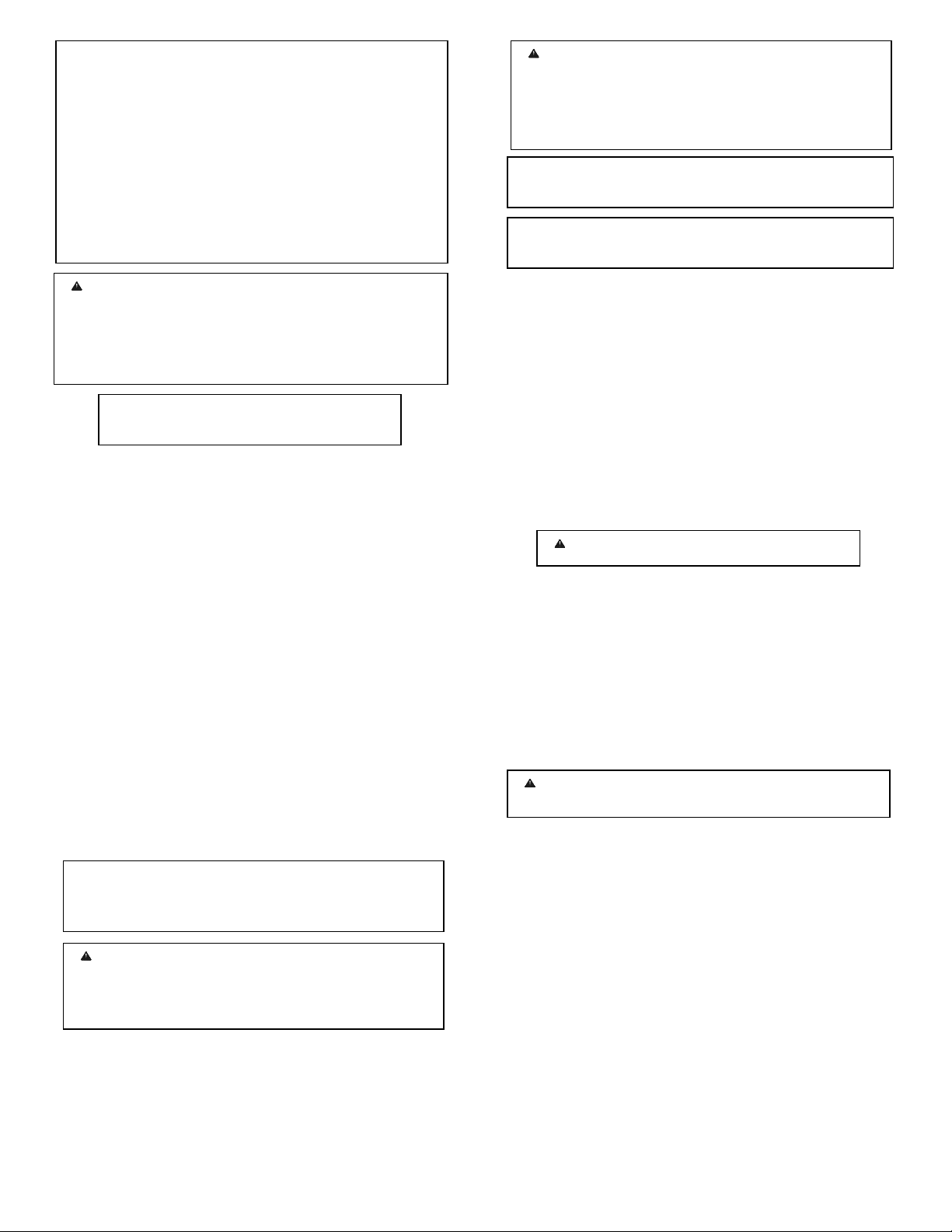
FRAMING AND INSTALLING THE FIREPLACE
STEP 1: Frame the opening for the fireplace using the
dimensions shown in figures 1 & 2.
STEP 2: If the fireplace is to be installed directly on carpeting,
tile (other than ceramic), or any combustible material other
than wood flooring, the fireplace must be installed upon a
metal or wood panel extending the full width and depth of the
fireplace.
WARNING: Do not install in a bedroom.
WARNING: Do not pack required air spaces with
STEP 3: Set the fireplace directly in front of this opening and
y
slide the unit back until the nailing flanges touch the side
framing.
STEP 4: Check the level of the fireplace and shim with sheet
metal if necessary. Make sure the unit is balanced on each
side.
Figure 1 FRAMING DIMENSION
Figure 2 CORNER INSTALLATION
Figure 3 TIE-DOWN STRAP
STEP 5: Before securing fireplace to prepared framing, the
ember protector (provided), must be placed between the hearth
extension (not supplied), and under the bottom front edge of
the fireplace to protect against glowing embers falling
through. If the fireplace is to be installed on a raised platform,
a Z-type ember protector (not supplied) must be fabricated to
fit your required platform height. The ember protector should
extend under the fireplace a minimum of 1 - 1/2”. The ember
protector should be made of galvanized sheet metal (28-gage
minimum).
STEP 6: Secure the fireplace to the floor using tie-down straps
(see figure 3) to prevent shifting.
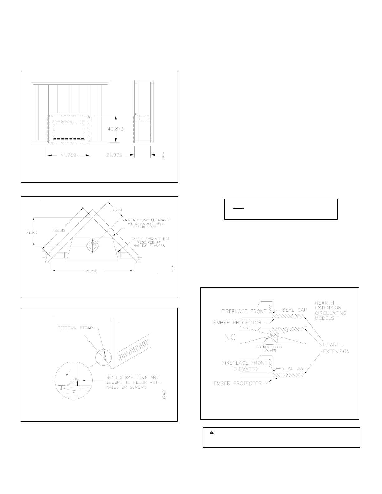
HEARTH EXTENSION
A hearth extension projecting a minimum of 16” in front of
and a minimum of 8” beyond each side of the fireplace
opening is required to protect combustible floor construction
in front of the fireplace. Fabricate a hearth extension using a
material which meets the following specifications: a layer of
non-combustible, inorganic material having a thermal
conductivity of K = 0.84 BTU IN/FT. HR. F (or less) at 1”
thick. For example, if the material selected has a K factor of
0.25, such as glass fiber, the following formula would apply:
0.25 x 1.0” = 0.30 thickness required
0.84
Thermal conductivity “K” of materials can be obtained from
the manufacturer or supplier of the non-combustible material.
If the hearth extension is to be covered, use non-combustible
material such as tile, slate, brick, concrete, metal, glass,
marble, stone etc. Provide a means to prevent the hearth
extension from shifting and seal gap between the fireplace
frame and hearth extension with a non-combustible material
(see figure 4).
Figure 4 HEARTH EXTENSION
WARNING: Hearth extension is to be installed onl
as illustrated.
- 3 - For more information, visit www.desatech.com
OUTSIDE AIR KIT (MODEL AK-6)
The installation of an outside air kit should be performed
during the rough framing of the fireplace due to the nature of
its location. Outside combustion air is accessed through the
mobile home floor (Refer to AK-6 Installation Instructions for
details). In some instances, a wall installation is required (see
Figure 5). Note: An AK-6WAI Air Kit must be ordered when
a sidewall installation is required (see accessories on page 12).
See page 10, figure 25 for instructions on how to operate the
air kit.
Figure 5 OUTSIDE AIR KIT
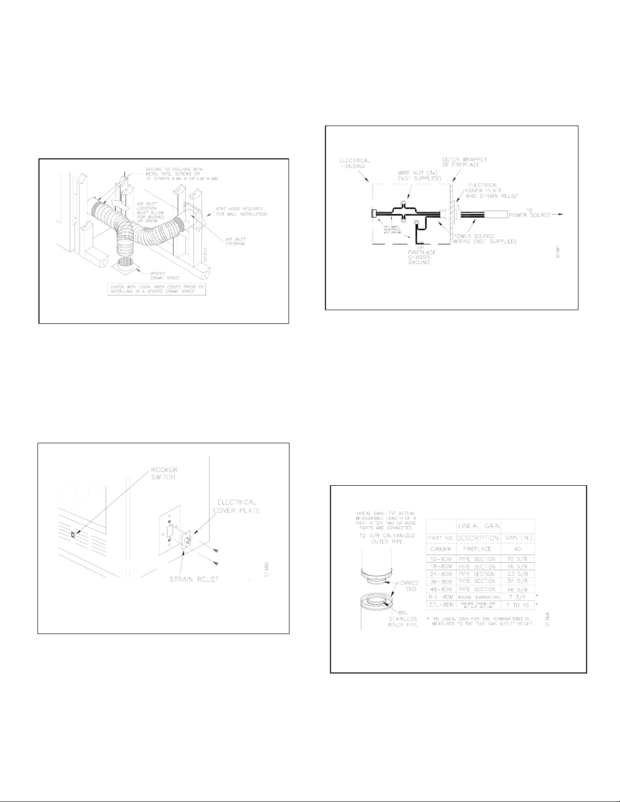
FAN KIT ASSEMBLY (BK3)
A fan kit assembly is preinstalled in this fireplace. Use of
blowers or fans other than manufactured by DESA voids the
warranty. The fan is operated by pressing the rocker switch
located at the lower right hand corner of the fireplace face.
Fan kit electrical connections are made through the electrical
cover plate located on the side of the fireplace as shown in
figure 6a.
Figure 6a FAN SWITCH AND STRAIN RELIEF
FAN KIT WIRING INSTRUCTIONS
i. Loosen the strain relief by turning the plastic screw
counterclockwise.
ii. Remove electrical cover plate (with strain relief)
from the fireplace by removing the two sheet metal
screws as shown in figure 6a.
iii. Slide power source wiring through the strain relief
opening and electrical cover plate and make all the
necessary connections.
iv. Slide all wiring connections in the electrical housing
as shown in figure 6b.
v. Secure the electrical cover plate with screws
previously removed.
vi. Tighten strain relief plastic screw.
NOTE: Electrical housing and cover plate have sharp edges,
wear protective gloves.
Figure 6b ELECTRICAL HOUSING
CHIMNEY PIPE
The DESA chimney system consists of 12, 18, 24, 36 and 48
inch, snap-lock double-wall pipe segments, planned for
maximum adaptability to individual site requirements. Actual
lengths gained after fitting overlaps must be taken into
consideration (lineal gain) and are given in the lineal gain
chart (see figure 7).
There are two vent kits available, which have been specially
designed for common installations in manufactured (mobile
homes): MW8K (8’ Vent Kit) and MW9K (9’ Vent Kit). The
contents of these kits are listed under accessories on page 12.
Most chimney systems for manufactured houses require a
standard straight installation as described in this section. If an
uncommon offset installation is required, see page 10.
Figure 7 LINEAL GAIN
Important: If the height of the chimney assembly exceeds
requirements for transportation of the home, the chimney
installation may be completed after the home is sited.
Note: the termination must always be installed after the home
is sited.
- 4 - For more information, visit www.desatech.com
 Loading...