

CANADIAN PORTABLE FORCED AIR HEATERS
OWNER’S MANUAL
MODELS: BC40, RC40, BC55T, RC55T, BC70T, RC70T, BC115CT,
RC115CT, BC165CT AND RC165CT
IMPORTANT: Read and understand this manual before
assembling, starting, or servicing heater.
Improper use of heater can cause serious injury. Keep
this manual for future reference.
TABLE OF CONTENTS
Safety Information ............................................... 2
Unpacking ........................................................... 2
Product Identification ...........................................
Assembly ............................................................. 4
Theory of Operation ............................................ 5
Fuels .................................................................... 5
Ventilation ........................................................... 6
Operation ............................................................ 6
Storing, Transporting, or Shipping .......................
Save this manual for future reference.
For more information, visit www.desatech.com
Preventative Maintenance Schedule ................... 7
Troubleshooting ...................................................
Service Procedures ............................................. 9
3
Wiring Diagrams ............................................... 15
Illustrated Parts Breakdown and Parts List ....... 16
Specifications ....................................................
Accessories ....................................................... 25
Warranty and Repair Service ............................ 28
7
8
24

SAFETY INFORMATION
IMPORTANT: Read this owner’s
manual carefully and completely
before trying to assemble, op
erate, or service this heater.
Improper use of this heater can
cause serious injury or death
from burns, fire, explosion,
electrical shock, and carbon
monoxide poisoning.
DANGER: Carbon monoxide
poisoning may lead to death!
Early signs of carbon monoxide poisoning resemble the flu, with headaches, dizziness, and/or
nausea. If you have these signs, the heater may not
be working properly. Get fresh air at once! Have
heater serviced. Some people (such as pregnant
women, persons with heart or lung disease, persons
with anemia, those under the influence of alcohol,
and those at high altitudes) are more affected by
carbon monoxide than others.
1. Use only kerosene, #1/#2 diesel/fuel oil, JET A
or JP-8 fuels to avoid risk of fire or explosion.
Never use gasoline, naphtha, paint thinners,
alcohol, or other highly flammable fuels.
2. Use only with the electrical voltage and fre
quency specified on model plate.
3. Heater must be grounded. Use only a properly
grounded three-wire extension cord. Plug into
grounded outlet only.
4. Use only in areas free of flammable vapors or
high dust content.
5. Minimum clearance from any combustible
materials: 8 feet (244 cm) from hot air outlet;
6 feet (183 cm) from top; and 2 feet (61 cm)
from sides and inlet.
6. Locate heater on a stable and level surface
while hot or operating or a fire may occur.
7. Use only in well ventilated areas. Provide venti
lation of at least three square feet (2,800 square
cm) for each 100,000 Btu/Hr of rating.
8. Keep children and animals away from heater
at all times.
9. Never start heater when combustion chamber
is hot or if fuel has accumulated in combus
tion chamber.
10. When used with a thermostat, heater may start
at anytime.
-
11. When heater is moved or stored, it must be in
a level position or fuel spillage may occur.
12. Use heater only in accordance with local
ordinances and codes.
13. Never use gasoline, crankcase drainings,
naphtha, paint thinners, alcohol, or other
highly flammable fuels.
14. Never use heater where gasoline, paint thin
ner, or other highly flammable vapors are
present.
15. Never use heater in living or sleeping areas.
16. Never leave a heater plugged in without adult
supervision if children or animals are likely to
be present.
17. Never move, handle, refuel, or service a hot,
operating, or plugged-in heater.
18. Never block air inlet at motor end (rear) of
heater.
19. Never attach duct work to front of heater.
20. Never attach heater to external fuel tank.
UNPACKING
1. Remove all protective packaging that has been
applied to heater for shipment
2. Remove heater from carton.
3. Check heater for any shipping damage. If dam
age is found, promptly inform dealer where
heater was purchased.
-
-
-
-
-
2
www.desatech.com
111168-01A
Hot Air
Outlet
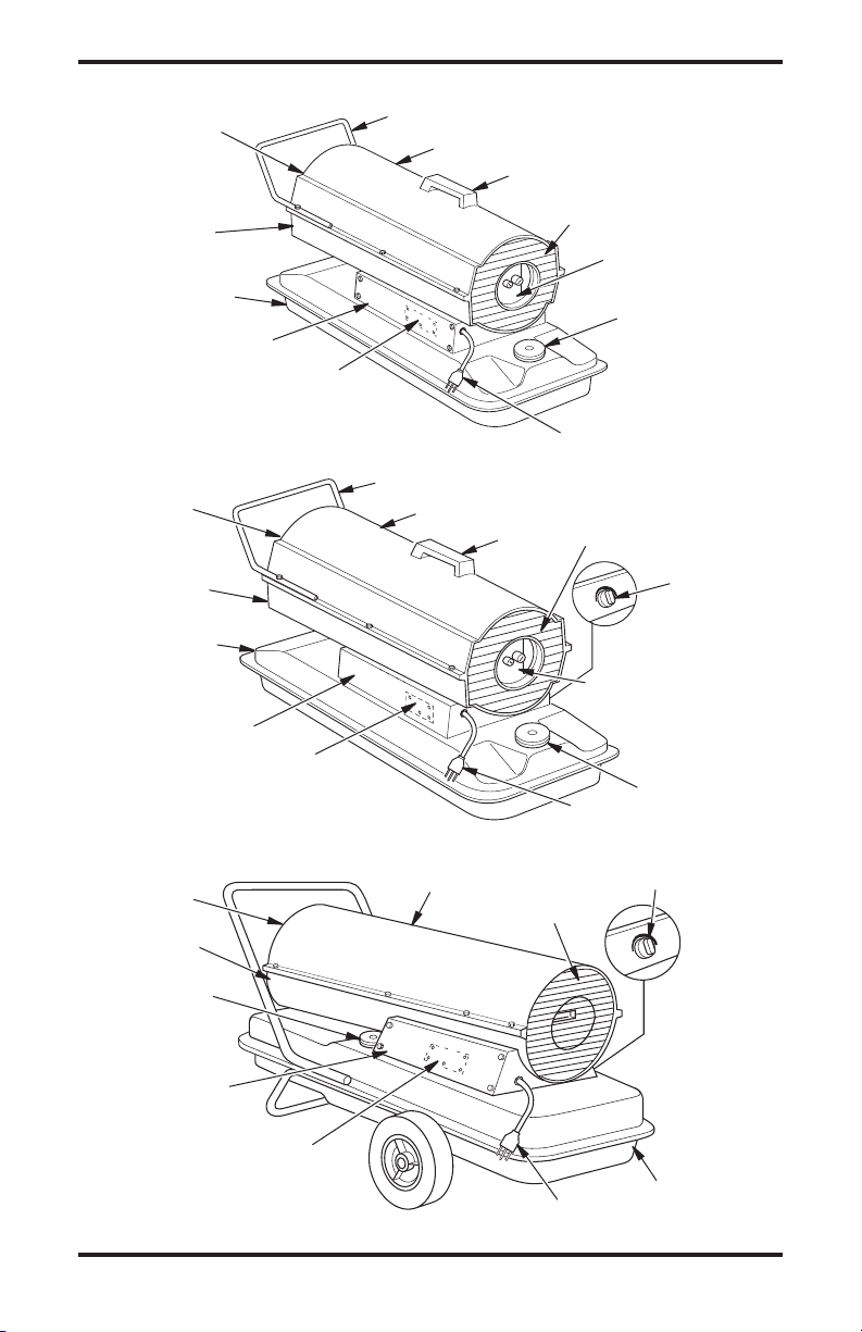
PRODUCT IDENTIFICATION
Nose Cone Guard
Upper Shell
Handle
Lower
Shell
Fuel Tank
Side Cover
Ignition Control Assembly
(assembly on inside of side cover)
Hot Air
Outlet
Lower
Shell
Fuel Tank
Side Cover
Ignition Control Assembly
(assembly on inside of side cover)
Figure 2 - 55T/70T Models
Hot Air
Outlet
Lower Shell
Figure 1 - 40 Model
Nose Cone Guard
Upper Shell
Upper Shell
Fan Guard
Power Cord
Handle
Fan Guard
Air Filter
End Cover
Fuel Cap
Fan Guard
Thermostat
Knob
Air Filter End
Cover
Fuel Cap
Power Cord
Thermostat Knob
Fuel Cap
Side Cover
Ignition Control Assembly
(assembly on inside of side cover)
Figure 3 - 115T/165T Models
www.desatech.com
Power Cord
Fuel Tank
3111168-01A
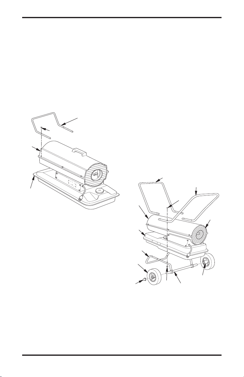
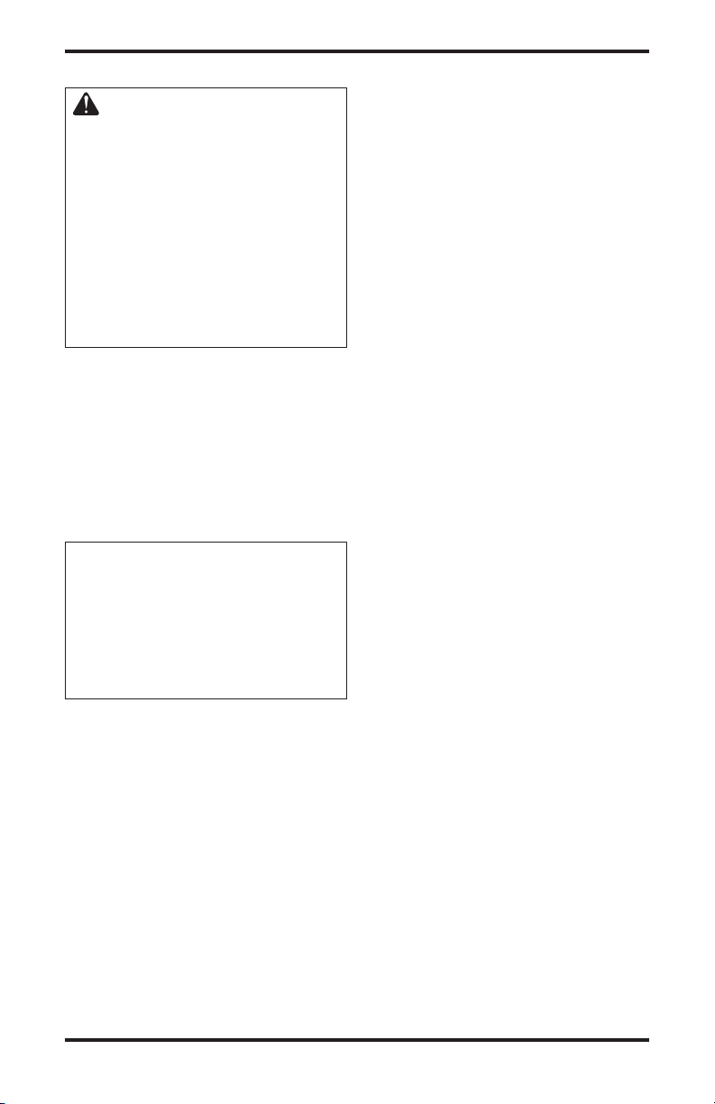
ASSEMBLY
(FOR 40, 55T, AND 70T MODELS ONLY)
These models are furnished with a nose cone
guard. Nose cone guard and mounting screws are
found in the shipping carton.
Tools Needed
• 5/16" Nut Driver or Wrench
1. Place nose cone guard on top of upper shell
flange. Make sure nose cone guard is on hot
air outlet end of heater.
2. Insert screws through nose cone guard and
upper shell flange.
3. Tighten screws firmly.
Nose Cone
Guard
Screw
Hot Air
Outlet
Upper Shell
Flange
(FOR 115T AND 165T MODELS ONLY)
These models are furnished with wheels and a front
handle. Some models are furnished with a rear
handle also. Wheels, handle(s), and the mounting
hardware is found in the shipping carton.
Tools Needed
• Medium Phillips Screwdriver
• 3/8" Open or Adjustable Wrench
• Hammer
1. Slide axle through wheel support frame. Install
wheels on axle.
IMPORTANT: Place extended hub of wheel
toward wheel support frame.
2. Place cap nuts on axle ends. Gently tap with
hammer to secure.
3. Place heater on wheel support frame assem
bly. Make sure air inlet end of heater is over
wheels.
4. Place front handle on top of fuel tank flange.
Insert screws through handle(s), fuel tank
flange and wheel support frame. Attach nut
finger tight after each screw is inserted.
5. Tighten all nuts firmly.
Front
Handle
Hot Air
Outlet
Rear Handle
(If Equipped)
Screw
-
Figure 4 - Nose Cone Guard Assembly,
40/55T/70T Models Only
4
www.desatech.com
Fuel Tank
Flange
Wheel
Support
Frame
Wheel
Nut
Cap Nut
Figure 5 - Wheel and Handle Assembly,
115T/165T Models Only
Axle
Air Inlet
Extended Hub
111168-01A
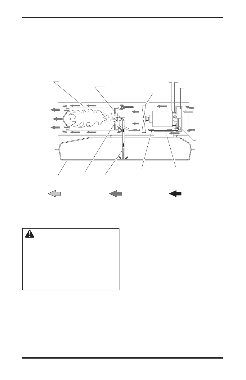
THEORY OF OPERATION
The Fuel System: The air pump forces air through
the air line. The air is then pushed through the
nozzle. This air causes fuel to be lifted from the
tank. A fine mist of fuel is sprayed into the combustion chamber.
The Air System: The motor turns the fan. The
fan pushes air into and around the combustion
chamber. This air is heated and provides a stream
of clean, hot air.
The ignition control assembly provides power to
the ignitor. This ignites the fuel/air mixture in the
combustion chamber.
The Flame-Out Control System: This system causes
the heater to shut down if the flame goes out.
Clean
Heated
Air Out
Fuel Tank
Combustion Chamber
Nozzle
Air For Fuel
System
Figure 6 - Cross Section Operational View
Ignitor
Fuel
Filter
FUELS
WARNING: Use only kerosene, #1/#2 diesel/fuel oil, JET
A or JP-8 fuels to avoid risk
of fire or explosion. Never
use gasoline, oil drained from
crankcases, naphtha, paint
thinners, alcohol or other highly
flammable fuels.
Use only kerosene, #1/#2 diesel/fuel oil, JET A
or JP-8 fuels. Heavier fuels such as No. 2 fuel
oil or No. 2 diesel fuel may also be used but will
result in:
• noticeable odor
• additional fuel filter maintenance
• the need for nontoxic, anti-icer additives in very
cold weather
Motor
Fan
Air Line
To Burner
Air For Combustion
And Heating
Do not use fuels heavier than No. 2 grade or
heavy oils such as oil drained from crankcases.
These heavy oils will not ignite properly and will
contaminate the heater.
IMPORTANT: Use a KEROSENE ONLY (blue)
or DIESEL ONLY (yellow) storage container. Be
sure storage container is clean. Foreign matter
such as rust, dirt, or water will cause the ignition
control assembly to shut down heater. Foreign
matter may also require heater's fuel system to be
frequently cleaned.
Air Pump
Air Intake
Filter
Cool
Air In
Air
Output
Filter
Ignition Control
Assembly
Fuel
www.desatech.com
5111168-01A
VENTILATION
WARNING: Provide a fresh air
opening of at least three square
feet (2,800 square cm) for each
100,000 Btu/Hr rating. Provide
extra fresh air if more heaters
are being used. The minimum
ventilation requirements must
be followed to avoid risks associated with carbon monoxide
poisoning. Make certain these
requirements are met prior to
operating heater.
Example: A 165 model heater requires one of
the following:
• a two-car garage door (16 ft. [4.88 m] wide
opening) raised four inches (10.16 cm)
• a single-car garage door (9 ft. [2.74 m] wide
opening) raised seven inches (17.78 cm)
• two, thirty-inch (76.20 cm) windows raised
twelve inches (30.48 cm)
OPERATION
IMPORTANT: Review and understand the warnings in the Safety
Information section, page 2.
They are needed to safely oper
ate this heater. Follow all local
ordinances and codes when
using this heater.
-
Extension Cord Size Requirement
6 to 10 feet (1.8 to 3 meters) long, use 18 AWG
(0.75 mm2) rated cord
11 to 100 feet (3.3 to 30.5 meters) long, use
16 AWG (1.0 mm2) rated cord
101 to 200 feet (30.8 to 61 meters) long, use
14 AWG (1.5 mm2) rated cord
6.
Plug extension cord into standard 120 volt/60
hertz, 3-prong grounded outlet. Note: Ignitor will
preheat for five seconds, then heater will start.
7. For thermostat models 55T, 70T, 115T, and
165T, adjust thermostat knob to the desired
setting. Not e: A cold heater may affect
the thermostat setting. This thermostat is a
general-heating control. It is not intended for
precise temperature control. Adjust thermostat
until heater cycles at the desired setting.
TO STOP HEATER
Unplug extension cord from outlet.
TO RESTART HEATER
1. Unplug extension cord from outlet and wait
10 seconds. (Wait two minutes if heater has
been running.)
2. Repeat steps under To Start Heater
.
TO START HEATER
1. Follow all ventilation and safety information.
2. Fill fuel tank with kerosene, #1/#2 diesel/fuel
oil, JET A or JP-8 fuels.
3. Attach fuel cap.
4. For thermostat models 55T, 70T, 115T, and
165T, turn thermostat knob clockwise to the
high position.
5. Plug heaterʼs power cord into approved,
grounded, three-wire extension cord. Extension
cord must be at least six feet (1.8 meters) long.
6
www.desatech.com
111168-01A
STORING, TRANSPORTING,
OR SHIPPING
Note: If shipping, transport companies require
fuel tanks to be empty.
1. Drain fuel tank.
Note: Some models have drain plug on un-
derside of fuel tank. If so, remove drain plug
to drain all fuel. If heater does not have drain
plug, drain fuel through fuel cap opening. Be
sure all fuel is removed.
2. Replace drain plug if provided.
3. If any debris is noted in old fuel, add 1 or 2
quarts of clean kerosene to tank, stir, and drain
again. This will prevent excess debris from
clogging filters during future use.
4. Replace fuel cap or drain plug. Properly dis
pose of old and dirty fuel. Check with local
automotive service stations that recycle oil.
5. If storing, store heater in dry place. Make sure
storage place is free of dust and corrosive
fumes.
IMPORTANT: Do not store kerosene over summer
months for use during next heating season. Using
old fuel could damage heater.
PREVENTATIVE MAINTENANCE SCHEDULE
WARNING: To avoid risk of burn and electrical shock, never at-
tempt to service heater while it is plugged in, operating, or hot.
Item How Often How To
Fuel tank Flush every 150-200 hours See Storing, Transporting, or
of operation or as needed Shipping
Air output and lint filters Replace every 500 hours of See Air Output, Air Intake,
operation or once a year and Lint Filters, page 10
Air intake filter Wash and dry with soap and See Air Output, Air Intake,
water every 500 hours of and Lint Filters, page 10
operation or replace as needed
Fuel filter Clean twice a heating season See Fuel Filter, page 11
or replace as needed
-
Ignitor None required
Fan blades Clean every season or See Fan, page 9
as needed
Motor Not required/permanently
lubricated
www.desatech.com
7111168-01A
TROUBLESHOOTING
WARNING: Never service heater while it is plugged in, operating,
or hot. Severe burns and electrical shock can occur.
FAULT CONDITION
Motor does not start five seconds
after heater is plugged in
Motor starts and runs but heater
does not ignite
POSSIBLE CAUSE
1. No power to heater
2. Thermostat setting is too low
WARNING: High voltage!
3. Bad electrical connection be
tween motor and ignition con
trol assembly or ignition control
assembly and power cord
4. Binding pump rotor
5. Defective ignition control as
sembly
6. Defective motor
1. No fuel in tank
2. Pump pressure incorrect
3. Dirty fuel filter
4. Obstruction in nozzle
5. Water in fuel tank
WARNING: High voltage!
6. Bad electrical connection
between ignitor and ignition
control assembly
7. Defective ignitor
8. Defective ignition control as
sembly
REMEDY
1. Check circuit breaker in electrical panel
2. Turn thermostat knob to a
higher setting
-
3. Check all electrical connec-
-
tions. See Wiring Diagrams
page 15
4. If fan does not turn freely, see
Pump Rotor, page 14
-
5. Replace ignition control as
sembly
6. Replace motor
1. Fill tank with kerosene
2. See Pump Pressure Adjust
ment, page 10
3. See Fuel Filter, page 11
4. See Nozzle Assembly, page 12
5. Drain and flush fuel tank with
clean kerosene. See Storing,
Trans porti ng, or Shipping
page 7
6.
Check electrical connections.
See Wiring Diagrams , page 15
7. Replace ignitor, see page 11
-
8. Replace ignition control as
sembly
,
-
-
,
-
Heater ignites but ignition control
assembly shuts heater off after a
short period of time
8
1. Pump pressure incorrect
2. Dirty air intake, air output,
and/or lint filter
3. Dirty fuel filter
4. Obstruction in nozzle
5. Photocell assembly not properly
installed (not seeing the flame)
6. Dirty photocell lens
WARNING: High voltage!
7. Bad electrical connection be
tween photocell and ignition
control assembly
8. Defective photocell
9. Defective ignition control as
sembly
www.desatech.com
1. See Pump Pressure Adjust
ment, page 10
2. See Air Output, Air Intake, and
Lint Filters, page 10
3. See Fuel Filter, page 11
4. See Nozzle Assembly, page 12
5. Make sure photocell boot is
properly seated in bracket
6. Clean photocell lens
-
7. Check electrical connections.
See Wiring Diagrams, page 15
8. Replace photocell
-
9. Replace ignition control as
sembly
111168-01A
-
-
SERVICE PROCEDURES
WARNING: To avoid risk of
burn and electrical shock, never
attempt to service heater while it
is plugged in, operating, or hot.
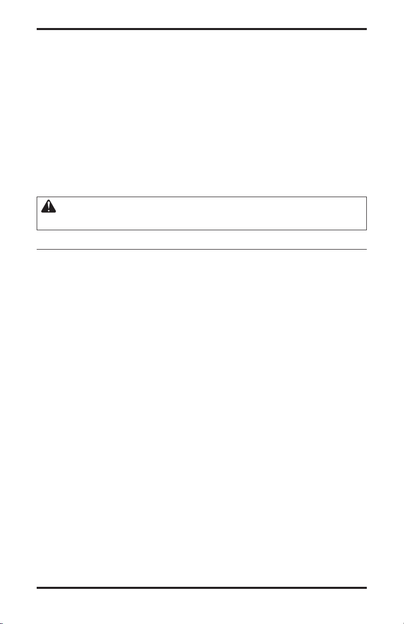
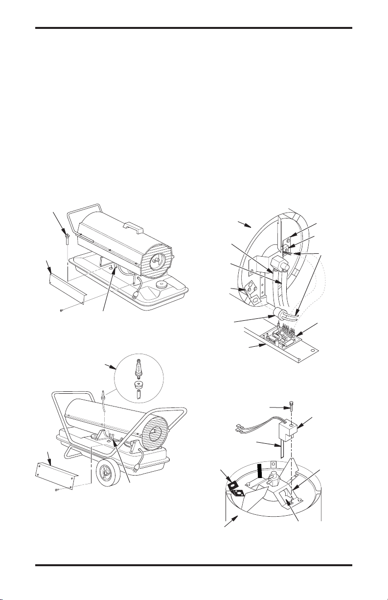
UPPER SHELL REMOVAL
1. Remove screws along each side of heater using
5/16" nut-driver. These screws attach upper
and lower shells together. See Figure 7 or 8.
2. Lift upper shell off.
3. Remove fan guard.
Screw
Upper Shell
Fan Guard
Figure 7 - Upper Shell Removal
(40/55T/70T Models Only)
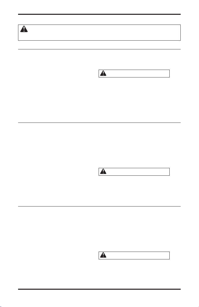
FAN
IMPORTANT: Remove fan from motor shaft
before removing motor from heater. The weight
of the motor resting on the fan could damage the
fan pitch (see Figure 9).
1. Remove upper shell (see Figure 7 or 8).
2. Use 1/8" allen wrench to loosen setscrew
which holds fan to motor shaft.
3. Slip fan off motor shaft.
4. Clean fan using a soft cloth moistened with
kerosene or solvent.
5. Dry fan thoroughly.
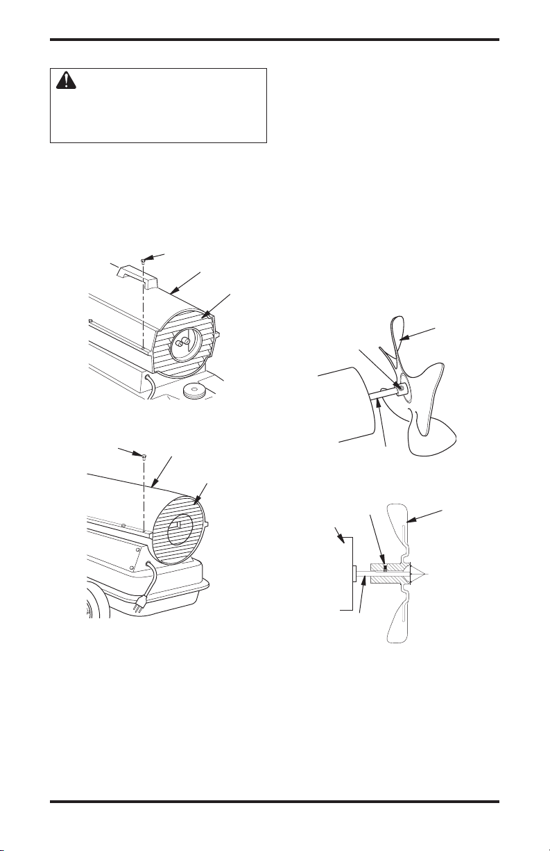
6. Replace fan on motor shaft. Place fan hub flush
with end of motor shaft (see Figure 10).
Place setscrew on flat of shaft. Tighten
7.
setscrew firmly (40-50 inch-pounds/4.5-
5.6 n-m).
8. Replace fan guard and upper shell.
Fan
Setscrew
Screw
Figure 8 - Upper Shell Removal
(115T/165T Models Only)
Upper Shell
Fan Guard
www.desatech.com
Motor Shaft
Figure 9 - Fan, Motor Shaft, and
Setscrew Location
Setscrew
Motor
Motor Shaft
Figure 10 - Fan Cross Section
Fan
Flush
9111168-01A
SERVICE PROCEDURES
Continued
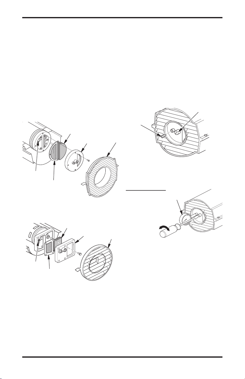
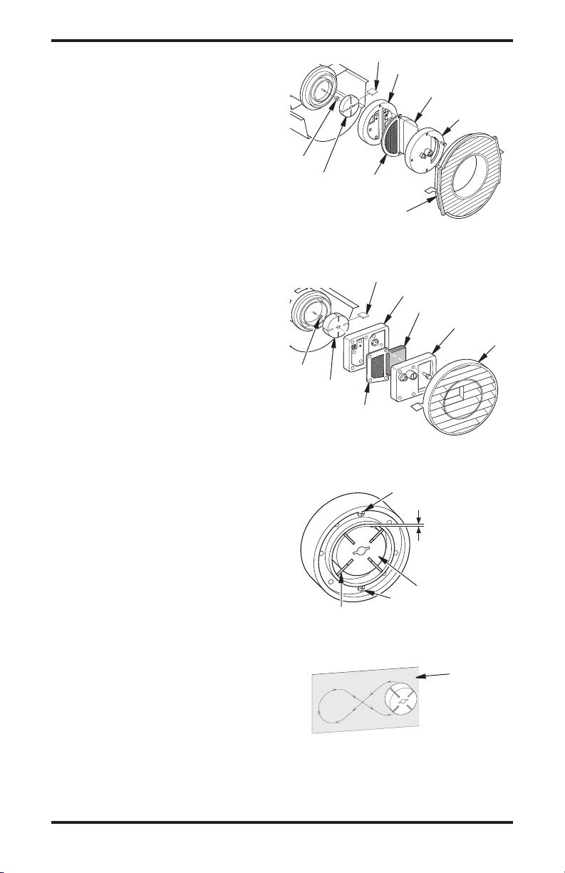
AIR OUTPUT, AIR INTAKE AND LINT
FILTERS
Remove upper shell (see Figure 7 or 8, page 9).
1.
2. Remove filter end cover screws using 5/16"
nut-driver. See Figure 11 or 12.
3. Remove filter end cover.
4. Replace air output and lint filters.
5. Wash or replace air intake filter (see Preventa
tive Maintenance Schedule, page 7).
6. Replace filter end cover.
7. Replace fan guard and upper shell.
IMPORTANT: Do not oil filters.
Air Intake
Filter
Filter End
Cover
Lint Filter
Air Output Filter
Figure 11 - Air Output, Air Intake, and
Lint Filters, 40/55T/70T Models
Air Intake
Filter
Filter End
Cover
Fan
Guard
Fan
Guard
PUMP PRESSURE ADJUSTMENT
1. Remove pressure gauge plug from filter end
cover (see Figure 13).
2. Install accessory pressure gauge (part number
HA1180).
3. Start heater (see
motor to reach full speed.
4. Adjust pressure. Turn relief valve to right to
increase pressure. Turn relief valve to left to
decrease pressure. See specifications correct
pressure for each model (see Figure 14).
-
5. Remove pressure gauge. Replace pressure
gauge plug in filter end cover.
Pressure
Gauge
Plug
Figure 13 - Pressure Gauge Plug
Removal (40/55T/70T Models Shown)
Pump
Model Pressure
40 3.0 PSI
55T 3.4 PSI
70 T 4.7 PSI
115T 5.1 PSI
165T 5.6 PSI
Figure 14 - Adjusting Pump Pressure
(40/55T/70T Models Shown)
Operation, page 6). Allow
Relief Valve
Pressure
Gauge
Lint Filter
Air Output
Filter
Figure 12 - Air Output, Air Intake, and
Lint Filters, 115T/165T Models
10
www.desatech.com
111168-01A
SERVICE PROCEDURES
Continued
FUEL FILTER
1. Remove side cover screws using 5/16" nutdriver.
2. Remove side cover.
3. Pull upper fuel line off fuel filter neck (see
Figure 15 or 16).
4. Carefully pry bushing, fuel filter, and lower
fuel line (115T/165T models only) out of fuel
tank (see Figure 16).
5. Wash fuel filter with clean fuel and replace in
tank.
6. Attach upper fuel line to fuel filter neck.
7. Replace side cover.
Fuel Filter
Side
Cover
IGNITOR
1. Remove upper shell and fan guard (See Upper
Shell Removal, page 9).
2. Remove fan (see page 9).
3.
Remove 4 side cover screws with a 5/16"
nut driver. Remove side cover (see Figures
15 and 16).
4. Disconnect ignitor wires (yellow) from ignition control assembly (see Figure 17). Pull
the ignitor wires up through the hole in the
lower shell.
5. Disconnect fuel line hose and air line hose.
Remove photocell from photocell bracket (see
Figure 17).
6. Remove combustion chamber. Stand com
bustion chamber on end with nozzle adapter
bracket on top (see Figure 18).
Nozzle
Combustion
Chamber
Air Line
Hose
Fuel Line
Hose
Photocell
Bracket
Adapter
Bracket
Ignitor
Ignitor Wire
(Yellow)
-
Upper Fuel Line
Figure 15 - Fuel Filter Removal,
40/55T/70T Models
Fuel Filter, Bushing,
and Lower Fuel Line
Side
Cover
Upper Fuel Line
Figure 16 - Fuel Filter Removal,
115T/165T Models
111168-01A
Photocell
Assembly
Side Cover
Figure 17 - Disconnecting Ignitor Wires
from Ignition Control Assembly
Ignitor Screw/
Washer Assembly
Ignitor Element
Photocell
Bracket
Combustion Chamber
Figure 18 - Ignitor Replacement
www.desatech.com
Ignition
Control
Assembly
Ignitor
Nozzle
Adapter
Bracket
Nozzle Adapter
Bracket Opening
11
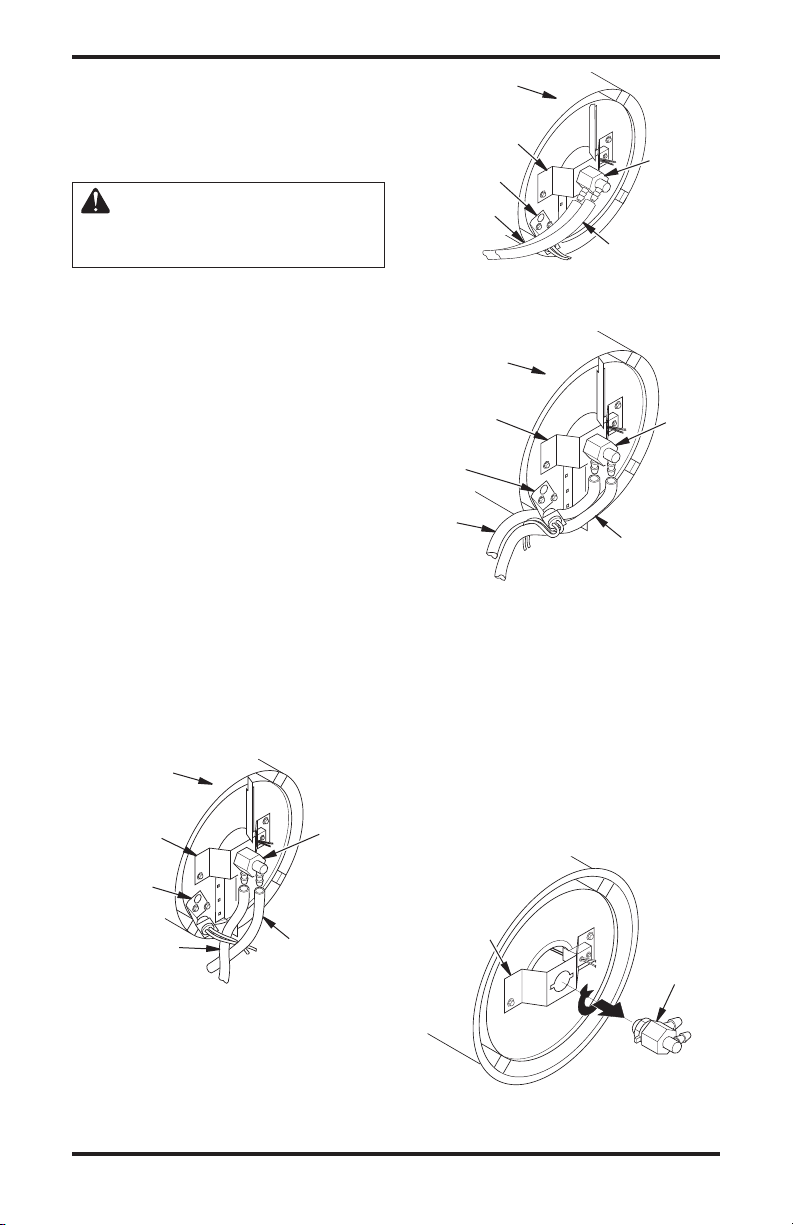
SERVICE PROCEDURES
Continued
7. Remove ignitor screw with a 1/4" nut driver.
Carefully remove ignitor from nozzle adapter
bracket.
CAUTION: Do not bend or
strike ignitor element. Handle
with care.
8. Carefully remove replacement ignitor from
styrofoam packing.
9. Carefully guide ignitor into opening in nozzle
adapter bracket. Do not strike ignitor element.
Attach ignitor to nozzle adapter bracket with
screw using a 1/4" nut driver (see Figure 18, page
11). Torque 8 to 15 in. lbs. Do not over torque.
10. Replace combustion chamber.
11. Route the ignitor wires back down through
the hole in the lower shell. Connect wires to
the ignition control assembly (see Figure 17,
page 11).
12. Replace side cover (see Figures 15 and 16,
page 11).
13. Connect and route fuel line hose and air line
hose to nozzle adapter assembly. See Fuel and
Air Line Replacement and Proper Routing
page 13.
14. Replace photocell in photocell bracket. Route
wires as shown in Figure 19, 20, or 21.
15. Replace fan (see
16. Replace fan guard and upper shell (see
Shell Removal, page 9).
Combustion
Chamber
Burner Strap
Photocell
Bracket
Air Line
Hose
Figure 19 - Removing Air and Fuel Line
Hoses, (40/55T/70T Models Only)
Fan, page 9).
Upper
Nozzle/
Adapter
Assembly
Fuel Line
Hose
Combustion
Chamber
Burner Strap
Photocell
Bracket
Air Line Hose
Figure 20 - Removing Air and Fuel Line
Hoses, (115T Model Only)
Combustion
Chamber
Burner Strap
Photocell
Bracket
Air Line
Hose
Figure 21 - Removing Air and Fuel Line
,
Hoses (165T Model Only)
Nozzle/
Adapter
Assembly
Fuel Line
Hose
Fuel Line
Hose
NOZZLE ASSEMBLY
1. Remove upper shell (see Upper Shell Removal, page 9).
2. Remove fan (see
3. Remove fuel and air line hoses from nozzle
assembly (see Figure 19, 20, or 21).
4. Turn nozzle assembly 1/4 turn to left and pull
toward motor to remove (see Figure 22).
5. Place plastic hex-body into vise and lightly
tighten.
Burner Strap
Fan, page 9).
Nozzle
Assembly
Nozzle/
Adapter
Assembly
Figure 22 - Removing Nozzle Assembly,
12
www.desatech.com
All Models
111168-01A
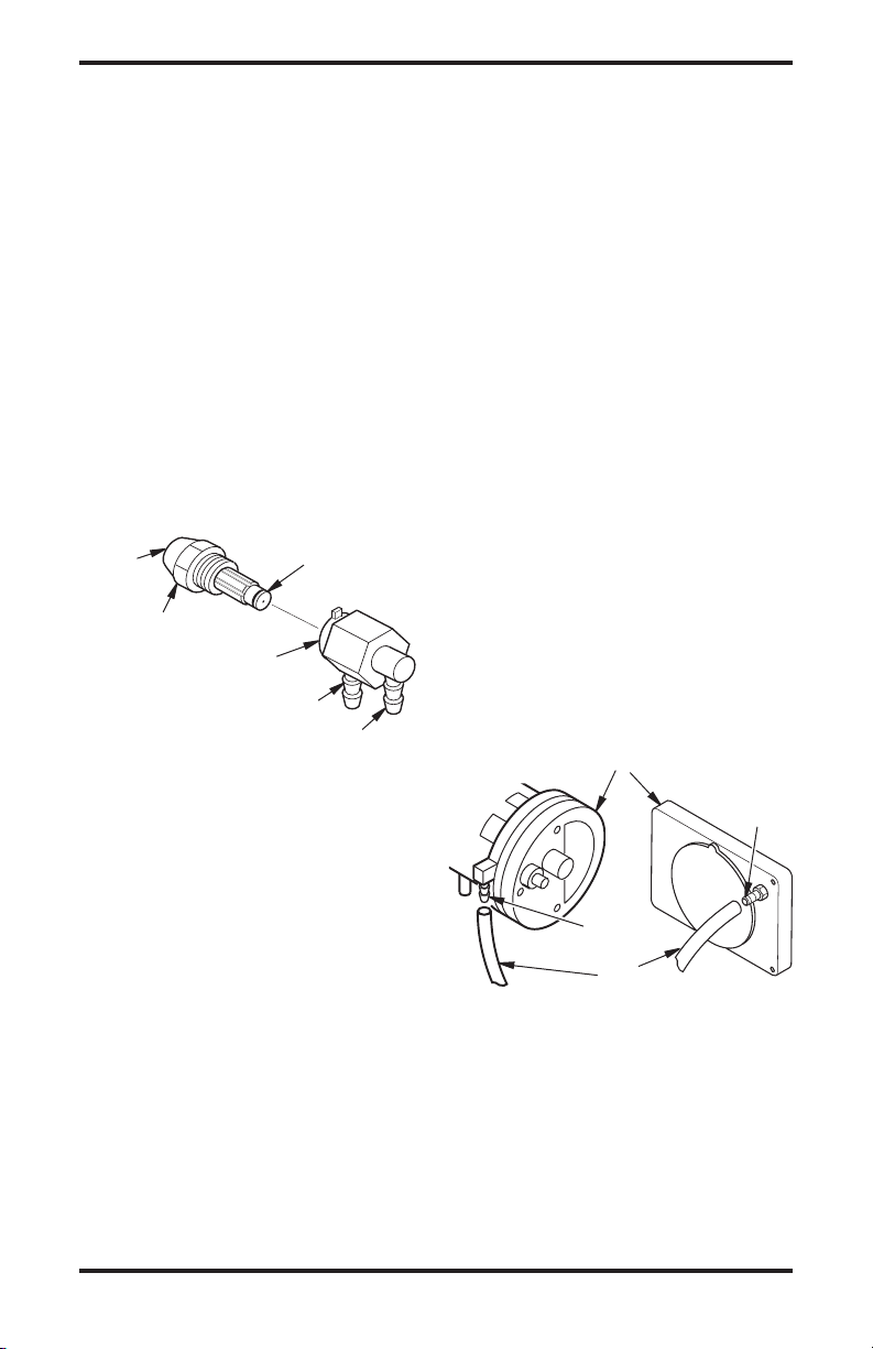
SERVICE PROCEDURES
Continued
6. Carefully remove nozzle from the nozzle adapter
using 5/8" socket wrench. See Figure 23.
7. Blow compressed air through face of nozzle.
This will free any dirt in nozzle area.
8. Inspect nozzle sleeve for damage.
9. Replace nozzle into nozzle adapter until
nozzle seats. Tighten 1/3 turn more using
5/8" socket wrench (40-45 inch-pounds). See
Figure 23.
10. Attach nozzle assembly to burner strap (see
Figure 22).
11. Attach fuel and airline hoses to nozzle adapter
assembly. See Fuel and Air Line Replacement
and Proper Routing
12. Replace fan (see
13. Replace fan guard and upper shell (see
Shell Removal, page 9).
Nozzle
Face
Nozzle
Nozzle Adapter
Figure 23 - Nozzle and Nozzle Adapter,
.
Fan, page 9).
Upper
Nozzle
Sleeve
Air Line Fitting
Fuel Line Fitting
All Models
FUEL AND AIR LINE REPLACEMENT
AND PROPER ROUTING
1. Remove upper shell (see Upper Shell Removal, page 9).
2. Remove side cover screws using 5/16" nut
driver (see Figure 15 or 16, page 11).
3. Remove side cover.
4. Inspect fuel and air line hoses for cracks and/or
holes. If fuel line hose is damaged, disconnect
from nozzle adapter (see Figure 19, 20, or 21,
page 12) and from fuel filter (see Fuel Filter
page 11). If air line hose is damaged, discon
nect from nozzle adapter (see Figure 19, 20,
or 21, page 12) and from barb fitting on pump
end cover (see Figure 24).
5. Install new air and/or fuel line. Attach one
end of air line hose to barb fitting on pump
end cover (see Figure 24) and the other end to
nozzle adapter (see Figure 19, 20, or 21, page
12). Attach one end of fuel line hose to fuel
filter (see Fuel Filter, page 11) and the other
end to nozzle adapter (see Figure 19, 20, or
21, page 12).
Note: Route hoses as shown in Figure 19, 20,
or 21, page 12, according to model. Hoses are
not to touch photocell bracket.
6. Replace side cover.
7. Replace upper shell and fan guard (see
Shell Removal, page 9).
Pump End Cover
Upper
Barb
Fitting
,
-
40/55T/70T
Models
Figure 24 - Air Hose to Barb Fitting
www.desatech.com
Barb
Fitting
Air Hose
115T/165T
Models
13111168-01A
SERVICE PROCEDURES
Continued
PUMP ROTOR
(Procedure if Rotor is Binding)
1. Remove upper shell (see Upper Shell Re
moval, page 9).
2. Remove filter end cover screws using 5/16"
nut-driver (see Figure 25 or 26).
3. Remove filter end cover and air filters.
4. Remove pump plate screws using 5/16" nutdriver.
5. Remove pump plate.
6. Remove rotor, insert, and blades.
7. Check for debris in pump. If debris is found,
blow out with compressed air.
8. Install insert and rotor.
9. Check gap on rotor. Adjust to .003"/.004"
(.076-.101 mm) if needed (see Figure 27).
Note: Rotate Rotor one full turn to insure the gap
is .003"/.004" (.076-.101 mm) at tightest position.
Adjust if needed.
10. Install blades, pump plate, air filters, and filter
end cover.
11. Replace fan guard and upper shell (see
Shell Removal, page 9).
12. Adjust pump pressure (see Pump Pressure
Adjustment, page 10).
Note: If rotor is still binding, proceed as follows.
13. Perform steps 1 thru 6.
14. Place fine grade sandpaper (600 grit) on flat
surface. Sand rotor lightly in “figure 8” motion
four times (see Figure 28).
15. Reinstall insert and rotor.
16. Perform steps 10 thru 12.
Upper
Blade
Pump Plate
Air Intake Filter
-
Insert
Rotor
Air Output
Filter
Fan Guard
Figure 25 - Rotor Location, 40/55T/70T
Insert
Rotor
Air Output
Filter
Figure 26 - Rotor Location, 115T/165T
Models
Blade
Pump Plate
Air Intake Filter
Filter End Cover
Models
Gap Adjusting Screw
.003"/.004"
(.076-.101 mm)
Gap Measured
With Feeler
Gauge
Filter End
Cover
Fan Guard
Rotor
Blade
Figure 27 - Gap Adjusting Screw
Figure 28 - Sanding Rotor
14
www.desatech.com
Gap Adjusting Screw
Locations
Sandpaper
111168-01A
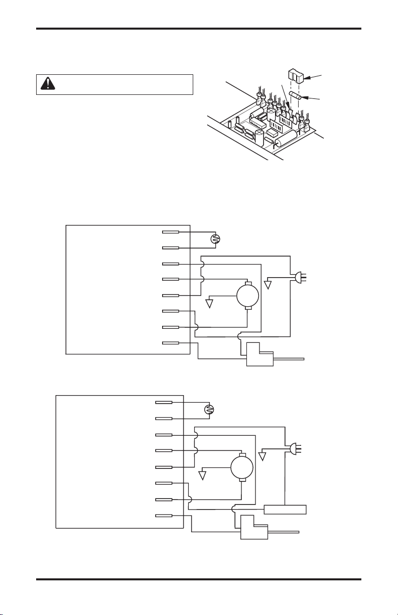
Power Plug
120V/60Hz
Blue
Blue
White
White
Photocell
Ignition Control Assembly
Green
Green
Red
Black
Black
Yellow
Yellow
Motor
Ignitor
Thermostat
Photocell
Photocell
Ignitor
Motor Return
AC Neutral (L2)
120V (L1)
Ignitor
Motor
Power Plug
120V/60Hz
Blue
Blue
White
White
Photocell
Green
Green
Red
Black
Ye
l low
Yel low
Motor
Ignitor
Ignition Control Assembly
Photocell
Photocell
Ignitor
Motor Return
AC Neutral (L2)
120V (L1)
Ignitor
Motor
SERVICE PROCEDURES
Continued
IGNITION CONTROL ASSEMBLY
WARNING: High Voltage!
1. Unplug heater.
2. Remove side cover screws (4) using 5/16"
nut-driver to expose ignition control assembly
(see Figure 15 or 16, page 11).
3. Remove fuse cover (see Figure 29).
4. Remove fuse from fuse clips (see Figure 29).
5. Replace fuse with fuse of the same type and
rating (GMA-10). Do not substitute a fuse
with a higher current rating.
WIRING DIAGRAMS
6. Replace fuse cover (see Figure 29).
Replace side cover (see Figure 15 or 16, page 11).
7.
Fuse
Clips
Fuse
Cover
Fuse
Figure 29 - Replacing Fuse
Figure 31 - Wiring Diagram for 55T/70T/115T/165T Thermostat Models
Figure 30 - Wiring Diagram for 40 Models
www.desatech.com
15111168-01A
1
2
3
4
31
5
6
7
8
9
10
11
12
13
14
15
16
9-2
9-1
9-3
9-4
9-5
17
18
19
20
21
22
23
24
25
26
27
28
29
30
34
35
36
32
33
9-6
37
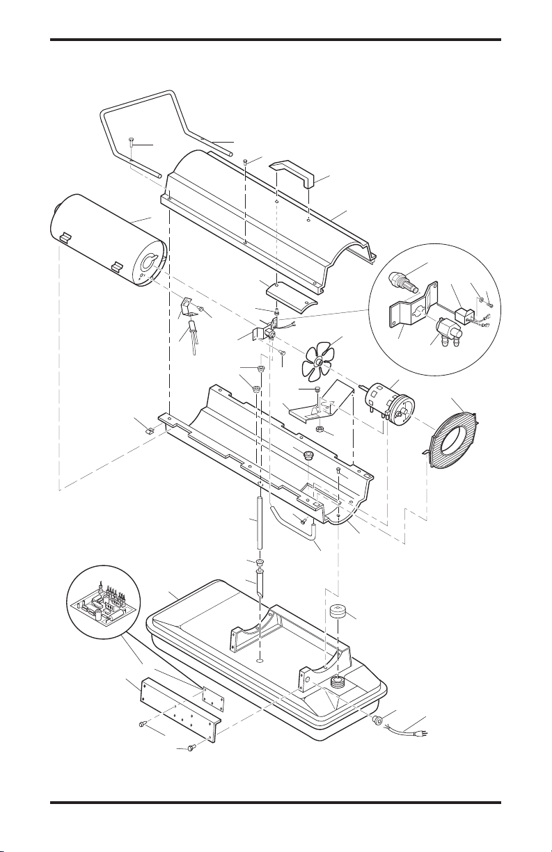
ILLUSTRATED PARTS BREAKDOWN
MODELS BC40 AND RC40
16
www.desatech.com
111168-01A

PARTS LIST
MODELS BC40 AND RC40
This list contains replaceable parts used in your heater. When ordering parts, be sure to provide the correct
model and serial numbers (from the model plate), then the part number and description of the desired part.
KEY PART
NO. NUMBER DESCRIPTION QTY.
1 M51104-01 Handle 1
2 098511-67 Upper Shell (Service Part Will Be Black) 1
3 M11084-29 Screw, #10-16 x 3/4" 2
4 108631-01 Screw, #10-16 x 1" 2
5 098512-58 Combustion Chamber 1
6 M10908-2 Screw, #6-32 x 3/8" 2
7 103154-03 Photocell Bracket 1
8 M16656-24 Photocell Assembly 1
9 ** Burner Head Assembly 1
9-1 HA3006 Nozzle Assembly 1
9-2 HA1000 Ignitor Kit 1
9-3 104056-01 Nozzle Adapter 1
9-4 102336-01 Nozzle Adapter Bracket 1
9-5 M10908-75 Screw, Hex Head, Tapping 1
9-6 103347-01 Belleville Washer 1
10 M11084-26 Screw, #10-16 x 3/8" 2
11 103684-01 Fan 1
12 ** Motor (see page 22) 1
13 M51105-01 Fan Guard 1
14 098219-38 Power Cord 1
15 M11143-1 Strain Relief Bushing 1
16 NTC-4C Hex Lock Nut, 1/4-20 2
17 M11084-26 Screw, #10-16 x 3/8" 4
18 M50631 Rubber Bumper 2
19 097461-09 Side Cover 1
20 101205-01 Motor Bracket 1
21 M30865-02 Bushing 2
22 M11271-8 Clip Nut 6
23 M50104-02 Bushing 1
24 M11084-26 Screw, #10-16 x 3/8" 6
25 097211-02 Screw, #8-18 x 1/2" 1
26 098511-234 Lower Shell (Service Part will be Black) 1
27 M50814-06 Rubber Airline 1
28 079973-01 Fuel Line 1
29 M50876-04 Fuel Filter with bushing 1
30 M10990-3 Rubber Bushing 1
31 079532-01 Guard, Nose Cone 1
32 102349-01 PCB Support 5
33 104068-02 Ignition Control Assembly 1
34 097702-01 Fuel Cap (Includes Gasket) 1
35 108088-01 Fuel Tank 1
36 M51108-01 Shell Heat-Shield 1
37 M15823-27 Screw, #10-16 x 1/2" 4
PARTS AVAILABLE - NOT SHOWN
103814-01 Wire Tie 1
105550-01 Warning/Maintenance Decal 1
105550-02 Warning/Maintenance Decal 1
** Not available as an assembly
www.desatech.com
17111168-01A

ILLUSTRATED PARTS BREAKDOWN
1
2
3
4
5
6
7
8
9
10
11
12
13
14
15
16
17
18
19
20
21
22
23
24
25
26
27
28
29
30
34
35
36
32
33
37
9-2
9-1
9-3
9-4
9-5
9-6
41
40
39
38
31
MODELS BC55T, RC55T, BC70T, AND RC70T
18
www.desatech.com
111168-01A

PARTS LIST
MODELS BC55T,
RC55T, BC70T,
AND RC70T
This list contains replaceable parts used in your
heater. When ordering
parts, be sure to provide
the correct model and se
rial numbers (from the
model plate), then the part
number and description of
the desired part.
** Not available as an
assembly
KEY PART
NO. NUMBER DESCRIPTION QTY.
1 M51104-01 Handle 1
2 098511-67
Upper Shell (Service Part Will Be Black)
3 M11084-29 Screw, #10-16 x 3/4" 2
4 108631-01 Screw, #10-16 x 1" 2
5 098512-50 Combustion Chamber (55T) 1
098512-51 Combustion Chamber (70T) 1
6 M10908-2 Screw, #6-32 x 3/8" 2
7 103154-03 Photocell Bracket 1
-
8 M16656-24 Photocell Assembly 1
9 ** Burner Head Assembly
9-1 HA3024 Nozzle Assembly (55T) 1
HA3026 Nozzle Assembly (70T) 1
9-2 HA1000 Ignitor Kit 1
9-3 104056-01 Nozzle Adapter 1
9-4 102336-02 Nozzle Adapter Bracket (55T) 1
102336-01 Nozzle Adapter Bracket (70T) 1
9-5 M10908-75 Screw, Hex Head, Tapping 1
9-6 103347-01 Belleville Washer 1
10 M11084-26 Screw, #10-16 x 3/8" 2
11 103684-01 Fan (55T) 1
M29678 Fan (70T) 1
12 ** Motor (see page 22) 1
13 M51105-01 Fan Guard 1
14 098219-38 Power Cord 1
15 M11143-1 Strain Relief Bushing 1
16 NTC-4C Hex Lock Nut, 1/4-20 2
17 M11084-26 Screw, #10-16 x 3/8" 4
18 M50631 Rubber Bumper 2
19 097461-09 Side Cover 1
20 101205-01 Motor Bracket 1
21 M30865-02 Bushing 2
22 M11271-8 Clip Nut 6
23 M50104-02 Bushing 1
24 M11084-26 Screw, #10-16 x 3/8" 6
25 097211-02 Screw, #8-18 x 1/2" 1
26 098511-234
Lower Shell (Service Part will be Black)
27 M50814-06 Rubber Airline 1
28 079973-01 Fuel Line 1
29 M50876-05 Fuel Filter (with bushing) 1
30 M10990-3 Rubber Bushing 1
31 WLE-2 Lock Washer, #8 1
32 102349-01 PCB Support 5
33 104068-02 Ignition Control Assembly 1
34 097702-01 Fuel Cap (Includes Gasket) 1
35 108088-03 Fuel Tank 1
36 M51108-01 Shell Heat-Shield 1
37 104458-01 Thermostat 1
38 M12461-18 Screw, #8-32 x 7/8" 1
39 104460-01 Thermostat Knob 1
40 M15823-27 Screw, #10-16 x 1/2" 4
41 079532-01 Guard, Nose Cone 1
PARTS AVAILABLE - NOT SHOWN
100621-09 Thermostat Decal 1
103814-01 Wire Tie 1
M9900-170 Wire Assembly 1
105550-01 Warning/Maintenance Decal 1
105550-02 Warning/Maintenance Decal 1
www.desatech.com
1
1
19111168-01A

1
2
3
23
19
9
10
16
11
12
15
25
26
27
24
28
29
20
22
21
30
31
17
14
14
33
34
35
36
32
26
18
5
4
6
7
8
7-2
7-1
7-5
7-4
7-3
39
38
37
41
41
47
45
44
46
42
43
40
7-6
13
ILLUSTRATED PARTS BREAKDOWN
MODELS BC115CT, RC115CT, BC165CT AND RC165CT
20
www.desatech.com
111168-01A

PARTS LIST
MODELS BC115CT, RC115CT, BC165CT AND RC165CT
KEY PART NUMBER
NO. 115T 165T DESCRIPTION QTY.
1 098511-292 098511-292 Upper Shell (Service Part Will Be Black) 1
2 M15823-27 M15823-27 Screw, #10-16 x 1/2" 8
3 098512-71 098512-75 Combustion Chamber 1
4 103154-05 M16660-02 Photocell Bracket 1
5 M10908-2 M10908-2 Screw, #6-32 x 3/8" 2
6 M16656-24 M16656-24 Photocell Assembly 1
7 *** *** Burner Head Assembly 1
7-1 HA3027 HA3028 Nozzle Assembly 1
7-2 HA1000 HA1000 Ignitor Kit 1
7-3 M10908-75 M10908-75 Screw, Hex Head, Tapping 1
7-4 102336-01 102336-01 Nozzle Adapter Bracket 1
7-5 104054-01 104054-01 Nozzle Adapter 1
7-6 103347-01 103347-01 Belleville Washer 1
8 M11084-27 M11084-27 Screw, #10-16 x 1/2" 2
9 097293-01 102042-01 Fan 1
10 *** *** Motor (see page 22) 1
11 M50631 M50631 Rubber Bumper 2
12 101206-01 101206-01 Motor Mounting Bracket 1
13 WLE-2 WLE-2 Washer, #8 1
14 104068-02 104068-02 Ignition Control Assembly 1
15 NTC-4C NTC-4C Hex Lock Nut, 1/4-20 2
16 111037-01 111037-01 Fan Guard 1
17 M27417 M27417 Drain Plug (Includes “o” Ring) 1
18 099213-01 099213-01 Button Plug 1
19 M51345-06 M51345-06 Fuel Line 1
20 106896-01** 106896-01** Fuel Filter 1
21 M51151-01 M51151-02 Fuel Line Tube 1
22 M10990-3 M10990-3 Rubber Bushing 1
23 M50814-03 M50814-03 Airline 1
24 098511-293 098511-293 Lower Shell (Service Part will be Black) 1
25 M50104-06 M50104-06 Bushing 1
26 M50104-01 M50104-01 Bushing 2
27 M11084-27 M11084-27 Screw, #10-16 x 1/2" 6
28 M11271-8 M11271-8 Clip Nut 8
29 M10908-14 M10908-14 Screw, #8-32 x 3/8" 1
30 108088-04 108088-05 Fuel Tank 1
31 097702-01 097702-01 Fuel Cap (Includes Gasket) 1
32 102349-01 102349-01 P.C. Board Support 5
33 M11143-1 M11143-1 Strain Relief Bushing 1
34 098219-38 098219-38 Power Cord 1
35 M51077-15 M51077-15 Side Cover 1
36 M11084-27 M11084-27 Screw, #10-16 x 1/2" 4
37 104458-01 104458-01 Thermostat 1
38 M12461-18 M12461-18 Screw, #8-32 x 7/8" 2
39 104460-01 104460-01 Thermostat Knob 1
40 079998-01 099614-01 Front Handle 1
41 M12345-33 M12345-33 Screw #10-24 x 1 3/4" 8
42 107426-01 107426-01 Wheels 2
43 M28526 M28526 Nut Cap 2
44 M12342-3 M12831-3 Wheel Support Frame 1
45 NTC-3C NTC-3C Hex Lock Nut, #10-24 6
46 M51015-01 M16801-2 Axle 1
_____
47
103814-01 103814-01 Wire Tie
HA1180 HA1180 Air Gauge Kit
HA2210 HA2210 Fuel Tank Filter Screen
HA3004 HA3004 Rotor Kit (M22456-1, M22009, M8643)
HA3017 HA3017 Filter Kit (M11637, M12179, M12244-1,106896-01)
HA3020 HA3020 Pump Kit (M27694, M10993-1, M22997,M8940)
100621-08 100621-08 Thermostat Decal 1
** See OPTIONAL ACCESSORIES *** Not available as an assembly.
099614-02 Rear Handle (If Equipped) 1
OPTIONAL ACCESSORIES
www.desatech.com
21111168-01A

ILLUSTRATED PARTS BREAKDOWN
MOTOR AND PUMP ASSEMBLY MODELS BC40, RC40, BC55T, RC55T,
BC70T AND RC70T
1
3
4
2
18
17
16
6
15
14
5
7
8
13
12
9
10
11
MODELS BC115CT, RC115CT, BC165CT AND RC165CT
1
2
3
4
5
17
16
15
13
14
22
www.desatech.com
6
13
12
7
8
9
10
11
111168-01A

This list contains replaceable parts used in your heater. When ordering parts, be sure to provide the correct
PARTS LIST
model and serial numbers (from the model plate), then the part number and description of the desired part.
MODELS BC40, RC40, BC55T, RC55T, BC70T AND RC70T
KEY PART
NO. NUMBER DESCRIPTION QTY.
1 102001-01 Motor (40 & 55T) 1
102001-20 Motor (70T)
2 079975-02 Pump Body (40 & 70T) 1
079975-03 Pump Body (55T)
3 M22009*, ** Insert 1
4 M22456-1* Rotor (40 & 70T) 1
M22456-2** Rotor (55T) 1
5 M29608 Pump End Cover 1
6 M29632*** Lint Filter 1
7 M29633*** Intake Filter 1
8 M29609 Filter End Cover 1
9 M12461-31 Screw, #10-32 x 1" 3
10 M27694 ∞ Adjusting Screw 1
11 M10993-1 ∞ Pressure Relief Spring 1
12 M22997 ∞ Plug 1
13 M8940 ∞ Steel Ball, 1/4" Diameter 1
14 M29612-01*** Output Filter 1
15 M12461-31 Screw, #10-32 x 1" (40 & 70T) 6
M12461-32 Screw, #10-32 x 1 1/8" (55T) 6
16 103676-01 Nylon Elbow, 90° 1
17 M8643* Blade (40 & 70T) 4
M8643-2** Blade (55T) 4
18 FHPF3-5C Screw (40 & 70T) 2
FHPF3-6C Screw (55T) 2
* Included in Rotor Kit (Part No. HA3004)
** Included in Rotor Kit (Part No. HA3005)
*** Included in Filter Kit (Part No. HA3014)
MODELS BC115CT, RC115CT, BC165CT AND RC165CT
KEY PART
NO. NUMBER DESCRIPTION QTY.
1 102001-30 Motor 1
2 079975-02 Pump Body 1
3 FHPF3-5C Screw, #10-32 x 5/8" 2
4 M22009** Rotor Insert 1
5 M22456-1** Pump Rotor 1
6 M50545 Pump End Cover 1
7 M12179** Intake Filter 1
8 M16545 Filter End Cover 1
9 M8940** Steel Ball, 1/4" Diameter 1
10 M10993-1** Relief Spring 1
11 M27694** Adjusting Screw 1
12 M22997** Plug 1
13 M12461-31 Screw, #10-32 x 1" 10
14 M12244-1** Output Filter 1
15 M11637** Lint Filter 1
16 M50820-02 Barb Fitting 1
17 M8643** Blade 4
** Included in Rotor Kit (Part No. HA3004)
∞ Included in Pump Adjustment Kit (Part No.
HA3020)
www.desatech.com
23111168-01A

SPECIFICATIONS
Model Size 40 55T 70T 115T 165T
Output Rating (Btu/Hr) 40,000 55,000 70,000 115,000 165,000
Fuel Use only kerosene, #1/#2 diesel/fuel oil, JET A or JP-8 fuels*
Fuel Tank Capacity
(U.S. Gal./Liters) 3/11.3 5/18.9 5/18.9 9/34 13.5/51
Fuel Consumption
(Gal. Per Hr/Liters Per Hr) .3/1.14 .44/1.67 .52/1.97 .85/3.00 1.2/4.54
Pump Pressure (psi) 3.0 3.4 4.7 5.1 5.6
Electric Requirements 120 V/60 HZ (Same All Models)
Amperage (Normal Run) 2.0 2.0 2.8 3.6 3.6
Motor RPM 1725 1725 3440 3440 3440
Hot Air Output (CFM) 170 180 360 490 575
Shipping Weight 32/14.5 35/15.9 35/15.9 54/24.5 65/29.5
(Approximate lbs./kg)
Heater Weight without Fuel 28/12.2 30/14 30/14 46/21 55/25
(Approximate lbs./kg)
* Use of #2 diesel & fuel oil will result in noticeable odor and could require additional fuel filter maintenance. Use in extreme cold temperatures may require nontoxic anti-icer additives.
24
www.desatech.com
111168-01A

ACCESSORIES
Heater accessories and parts are available at your
local dealer. Should your dealer not stock or is unable to order a particular accessory or part, please
contact DESA Industries for more information.
DESA Industries of Canada, Inc.
2220 Argentia Road, Unit #4
Mississauga, Ontario L5N 2K7
Parts Department
1-905-826-8010
AIR GAUGE KIT - HA1180
For all models. Special tool to check pump
pressure.
THERMOSTAT KIT - HA1210
For 40 model. Keeps your building at the temperature you select day and night. Helps economize
on fuel.
IGNITION CONTROL ASSEMBLY/
PHOTOCELL TESTER - HA1170
Special tool used to test the ignition control assembly and photocell.
HEAVY DUTY WHEELS AND
HANDLE KIT - HA1202
For heavy duty applications. Makes your heater even more portable and convenient. Fits
40/55T/70T models.
www.desatech.com
25111168-01A

WARRANTY AND REPAIR SERVICE
KEEP THIS WARRANTY
Model No.
Serial No.
Date of Purchase
(To be filled in by purchaser)
LIMITED WARRANTY
DESA Industries warrants this product and any parts thereof, to be free from defects in materials and workmanship
for one (1) year from the date of first purchase when operated and maintained in accordance with instructions. This
warranty is extended only to the original retail purchaser, when proof of purchase is provided.
This warranty covers only the cost of parts and labor required to restore the product to proper operating condition.
Transportation and incidental costs associated with warranty repairs are not reimbursable under this warranty.
Warranty service is available only through authorized dealers and service centers.
This warranty does not cover defects resulting from misuse, abuse, negligence, accidents, lack of proper main
tenance, normal wear, alteration, modification, tampering, contaminated fuels, repair using improper parts, or
repair by anyone other than an authorized dealer or service center. Routine maintenance is the responsibility of
the owner.
THIS EXPRESS WARRANTY IS GIVEN IN LIEU OF ANY OTHER WARRANTY EITHER EXPRESSED
OR IMPLIED, INCLUDING WARRANTIES OF MERCHANTABILITY AND FITNESS FOR A PARTICULAR
PURPOSE.
DESA Industries assumes no responsibility for indirect, incidental or consequential damages. Some states do
not allow the exclusion or limitation of incidental or consequential damages or limitations or exclusions may not
apply to you. This Limited Warranty gives you specific legal rights and you may also have other rights which
vary from province to province.
WARRANTY SERVICE
Should your heater require service, return it to your nearest authorized service center. Proof of purchase must be
presented with the heater. The heater will be inspected. A defect may be caused by faulty materials or workmanship.
If so, DESA Industries will repair or replace the heater without charge.
REPAIR SERVICE
Return the heater to your nearest authorized service center. Each Service Center is independently owned and operated.
Repairs not covered by the warranty will be billed at standard prices. We reserve the right to amend these specifications
at any time without notice.
Illustrated parts lists can be obtained free of charge. Send a self-addressed stamped envelope to the address listed
below. List the heater model number and the date located in the lower right corner of this page. A service manual may
be purchased from the address listed below. Send a cheque for $5.00 payable to DESA Industries.
When writing for information regarding your heater, be sure to include the model number and serial number as shown
on the model plate.
-
Printed in USA
2220 Argentia Road, Unit #4
Mississauga, Ontario L5N 2K7
(905) 826-8010
Fax (905) 826-8236

APPAREILS DE CHAUFFAGE PORTATIFS
CANADIENS À AIR FORCÉ
GUIDE DU PROPRIÉTAIRE
MODÈLES: BC40, RC40, BC55T, RC55T, BC70T, RC70T, BC115CT,
RC115CT, BC165CT ET RC165CT
IMPORTANT : Assurez-vous d’avoir lu et compris ce guide
avant de commencer à monter, utiliser ou réparer cet appareil. Une mauvaise utilisation de cet appareil pourrait
causer des blessures graves. Gardez ce guide pour vous
y reporter plus tard.
TABLE DES MATIÈRE
Informations Sur La Sécurité ............................... 2
Deballage ............................................................ 2
Nomenclature des pieces principales .................. 3
Montage .............................................................. 4
Principes de fonctionnement ............................... 5
Combustibles ....................................................... 5
Ventilation ........................................................... 6
Fonctionnement .................................................. 6
Entreposage, transport ou expédition ................. 7
Conservez le présent manuel pour consultation future.
Pour en savoir davantage, visitez le www.desatech.com
Calendrier d’entretien .......................................... 7
Diagnostic des pannes ........................................ 8
Entretien marche a suivre ................................... 9
Schemas electriques ....................................... 15
Vue détaillée et liste des pièces ........................
Fiche technique ................................................. 24
Accessoires ....................................................... 25
Ntie et service apres-vente ....... Couverture arrière
16

INFORMATIONS SUR LA
SÉCURITÉ
IMPORTANT : Veuillez lire ce
guide attentivement et complètement avant d’essayer de
monter, de faire fonctionner
ou de réparer cet appareil. Son
utilisation incorrecte pourrait
causer des blessures graves
ou la mort à la suite de brûlures, d’incendie, d’explosion, de
chocs électriques et d’intoxication par l’oxyde de carbone.
DANGER : L’intoxication
par l’oxyde de carbone risque
d’entraîner la mort !
Les signes précurseurs de lʼintoxication par lʼoxyde
de carbone ressemblent à ceux de la grippe : maux
de tête, vertiges et/ou nausée. Si vous ressentez ces
symptômes, il se peut que lʼappareil de chauffage
ne fonctionne pas correctement. Allez immédiate
ment respirer de lʼair frais! Faites réparer lʼappa
reil de chauffage. Certaines personnes (comme les
femmes enceintes, celles souffrant de maladies du
coeur ou des poumons, celles ayant de lʼanémie,
celles étant sous lʼinfluence de lʼalcool, celles se
trouvant à haute altitude) sont plus affectées que
dʼautres par lʼoxyde de carbone.
Assurez-vous dʼavoir lu et compris tous les avertis
sements. Gardez ce guide pour vous y reporter plus
tard. Il est essentiel pour lʼutilisation sécuritaire et
correcte de cet appareil de chauffage.
1. Utiliser uniquement du kérosène, du mazout/
carburant diesel NO 1 ou NO 2, des Carbu
réacteurs A ou JP-8.
2. Branchez-le sur une prise de tension et de
fréquence qui correspond à celles
indiquées sur la plaque signalétique.
3. Lʼappareil de chauffage doit être mis à la terre.
Ne vous servez que dʼune rallonge à trois fils.
Ne le branchez que dans une prise de courant
reliée à la terre.
4. Nʼutilisez pas lʼappareil dans des endroits
qui contiennent des vapeurs inflammables,
ou poussiéreux.
5.
La distance minimale de lʼappareil de tout matériau
combustible est de 244 cm (8 pieds) pour la sortie
dʼair chaud; de 183 cm (6 pieds) pour le dessus et
de 61 cm (2 pieds) pour les côtés et lʼentrée.
6. Pour éviter les risques dʼincendie lorsque
lʼappareil fonctionne ou est chaud, il doit être
sur une surface ferme et plate.
7. Ne le faites fonctionner que dans des endroits
bien aérés. Assurez un espace ouvert dʼau
moins 0,3 m2 (3 pieds carrés) pour chaque
100 000 Btu de rendement.
8. Ne laissez jamais les enfants ou les animaux
domestiques sʼapprocher de lʼappareil de
chauffage.
9. Nʼallumez jamais lʼappareil si la chambre de
combustion est chaude ou si du combustible
sʼy est accumulé.
10. Avec un thermostat, lʼappareil peut sʼallumer
sans préavis.
11. Pour éviter les renversements de combustible
lorsque lʼappareil est déplacé ou entreposé, il
doit se trouver de niveau.
12. Utilisez lʼappareil uniquement en suivant les
règlements et les codes locaux.
13. Ne vous servez jamais dʼessence, dʼhuile de vi
dange, de naphte, de térébenthine, dʼalcool, ou
de tout autre combustible très inflammable.
14. Nʼallumez jamais lʼappareil dans un endroit
contenant des vapeurs dʼessence, du diluant à
-
peinture, ou tout autre produit inflammable.
-
15. Nʼutilisez jamais lʼappareil à des fins domes
tiques ou dans une chambre à coucher.
16. Ne laissez jamais lʼappareil branché sans la
présence dʼun adulte lorsquʼil y a possibilité que
des enfants ou des animaux sʼen approchent.
17. Nʼeffectuez aucune intervention dʼentretien,
ne remplissez jamais le réservoir et ne dépla
cez pas lʼappareil sʼil est chaud, en marche,
ou branché.
18. Ne bloquez jamais lʼentrée dʼair arrière (côté
moteur).
19. Ne montez jamais de gaine à lʼavant de lʼap
pareil.
20. Ne branchez jamais lʼappareil à un réservoir
auxiliaire.
DEBALLAGE
1. Retirez tous les emballages de protection
utilisés pour le transport.
2. Retirez lʼappareil de la boîte.
3. Vérifiez lʼétat de lʼappareil. Sʼil est endom
magé, avertissez immédiatement le conces
sionnaire qui vous lʼa vendu.
-
-
-
-
-
-
2
www.desatech.com
111168-01A

NOMENCLATURE DES PIECES PRINCIPALES
Sortie d’air
chaud
Boîtier
Réservoir
de combustible
Plaque amovible
Commande d’allumage
(se trouve derrière la plaque
amovible)
Sortie d’air
chaud
Boîtier
Réservoir
de combustible
Barre de protection
Couvercle
Figure 1 - Modèle 40
Barre de protection
Couvercle
Poignée
Poignée
Grille de protection
du ventilateur
Cache-filtre
Cordon électrique
Grille de protection
du ventilateur
Cache-filtre
Bouchon du réservoir
de combustible
Bouton de
thermostat
Plaque amovible
Commande d’allumage
(se trouve derrière la plaque
amovible)
Sortie d’air
chaud
Boîtier
Bouchon du
réservoir de
combustible
Plaque amovibl
Commande d’allumage
(se trouve derrière la plaque
amovible)
Figure 2 - Modèles 55T/70T
Couvercle
Figure 3 - Modèles 115T/165T
www.desatech.com
Grille de
protection
du ventilateur
Cordon électrique
Bouchon du
réservoir de
combustible
Cordon électrique
Bouton de thermostat
Réservoir
de combustible
3111168-01A

MONTAGE
(POUR LE MODÈLES 40, 55T ET 70T
SEULEMENT)
Ces modèles sont livré avec une barre de protection. Cette barre se trouve, avec ses vis de montage,
dans la boîte dʼemballage.
Outillage nécessaire
• Clé plate ou tourne-écrous de 5/16 po
1. Placez les bras de la barre de protection sur le
rebord du couvercle. Assurezvous que la barre
se trouve du côté de la sortie dʼair chaud de
lʼappareil.
2. Faites passer les vis dans les trous de fixation
de la barre et vissez-les sur le rebord du cou
vercle.
3. Serrez les vis fermement.
Barre de
protection
Vis
Sortie
d’air
chaud
Robord
Nervure du
couvercle
Figure 4 - Montage de la barre de
protection, modèles 40, 55T et 70T
seulement
(POUR LES MODÈLES 100 ET 150
SEULEMENT)
Ces modèles sont livrés avec des roues et un
guidon pour la partie avant. Certains modèles
sont également livrés avec un guidon arrière. Les
roues et le(s) guidon(s) se trouvent dans la boîte
dʼemballage.
Outillage nécessaire
• Tournevis cruciforme de taille moyenne
• Clé plate ou clé à molette de 3/8 po
• Marteau
1. Faites passer lʼaxe au travers des alésages du
berceau. Installez les roues sur lʼaxe.
IMPORTANT: Installez les roues avec les
-
moyeux tournés vers le berceau.
2. Engagez un capuchon sur chaque bout de
lʼaxe. Tapez légèrement pour bien les mettre
en place.
3. Placez lʼappareil sur le berceau en vous assu
rant que lʼentrée dʼair se trouve au-dessus des
roues.
4. Placez le guidon avant sur le rebord du réser
voir. Faites passer les vis au travers des trous
du guidon, du rebord du réservoir et du berceau.
Serrez un écrou à la main sur chaque vis.
5. Serrez fermement tous les écrous à la clé.
Guidon avant
Sortie
d’air
chaud
Rebord du
réservoir
Guidon arrière
(si équipé)
Vis
-
-
Entrée
d’air
Berceau
Roue
Capuchon
Figure 5 - Montage des roues et
des guidons, modèles 115T et 165T
4
www.desatech.com
Ecrou
seulement
Moyeu
Axe
111168-01A

PRINCIPES DE
FONCTIONNEMENT
Circuit d’alimentation en combustible :
force lʼair dans la conduite dʼair. Lʼair est alors poussé
à travers la buse. Cela provoque la montée du combustible du réservoir. Un fin brouillard de combustible est
vaporisé dans la chambre de combustion.
Chambre de
combustion
La pompe à air
Allumeur
Circuit d’air :
Celui-ci pousse lʼair dans la chambre de combustion
et autour dʼelle. Lʼair est chauffé et produit un courant
dʼair propre chaud.
Dispositif d’allumage :
met lʼallumeur sous tension. Cela allume le mélange
combustible-air dans la chambre de combustion.
Système détecteur d’extinction de flamme :
lʼarrêt de lʼappareil de chauffage si la flamme sʼéteint.
Le moteur fait tourner le ventilateur.
La commande dʼallumage
Moteur
Ventilateur
Filtre d’entrée d’air
Entrée d’air
froid
Provoque
Sortie
d’air
chaud
Réservoir de
combustible
Buse
Air de
combustion
Figure 6 - Coupe, principe de fonctionnement
Filtre à
combustible
COMBUSTIBLES
AVERTISSEMENT :Pour éviter
les risques d’incendie ou d’explosion, utilisez seulement du
kérosène ou du mazout/carburant
diesel no 1 et no 2. Ne vous servez jamais d’essence, d’huile de
vidange, de naphte, de diluant à
peinture, d’alcool ou de tout autre
combustible très inflammable.
Utilisez seulement du kérosène ou du mazout/carburant diesel no 1 et no 2, des carburéacteurs A ou
JP-8. Les huiles plus lourdes comme le mazout no 2
ou le carburant diesel no 2 peuvent également être
utilisées, mais elles occasionneront :
• des odeurs perceptibles
• lʼentretien supplémentaire du filtre de carburant
• le besoin dʼajouter des additifs antigivrants non
toxiques à des températures très froides
www.desatech.com
Filtre de
sortie d’air
Conduite d’air
au brûleur
Air de combustion
et de chauffage
Nʼutilisez pas dʼhuiles plus lourdes que le grade
no 2 ou des huiles lourdes qui proviennent de la
vidange des moteurs. Ces huiles lourdes ne sʼen
flammeront pas bien et contamineront lʼappareil.
IMPORTANT : Utilisez un récipient de stockage
pour KÉROSÈNE SEULEMENT (bleu) ou pour
DIESEL SEULEMENT (jaune). Assurez-vous que
le récipient de stockage est propre. Toute matérière
étrangère, telle que la rouille, la saleté ou lʼeau,
provoquera lʼarrêt de lʼappareil de chauffage par la
commande dʼallumage. Ces matières risquent égale
ment dʼengendrer un nettoyage fréquent du système
dʼalimentation à combustible de lʼappareil.
Commande
d’allumage
Combustible
-
-
5111168-01A

VENTILATION
AVERTISSEMENT : Prévoyez
une ouverture d’au moins 2800
cm2 (3 pi2) pour l’air frais extérieur pour chaque 29,3 kW (100
000 BTU/h) de capacité. Dans
les cas où plus d’un appareil
est utilisé, prévoir une entrée
d’air supérieure pour éviter les
risques d’asphyxie par oxyde
de carbone. Respectez les rè
gles minimales de ventilation.
Assurez-vous que ces règles
sont bien suivies avant de faire
fonctionner l’appareil.
Exemple: Un modèle 165 doit opérer dans les
conditions suivantes:
• Une porte de garage pour deux voitures (ouverture
de 4,88 m [16 pi] de large) relevée de 10,16 cm
(4 po)
• Une porte de garage pour une seule voiture
(ouverture de 2,74 m [9 pi] de large) relevée
de 17,78 cm (7 po)
• Deux fenêtres de 76,20 cm (30 po) relevée de
30,48 cm (12 po)
FONCTIONNEMENT
IMPORTANT : Révisez et assurez-vous de comprendre les
avertissements qui se trouvent
dans les notes sur la sécurité.
Lorsque vous vous servez de cet
appareil de chauffage. Respectez tous les règlements locaux
et les normes régissant l’emploi
de cet appareil.
4. Pour les modèles 55T, 70T, 115T et 165T à
thermostat, tournez le bouton du thermostat
vers la droite en position maximum.
5. Branchez le cordon électrique à une rallonge à
trois fils avec mise à la terre. La rallonge doit
avoir une longueur dʼau moins 1,8 m (6 pi).
Conditions requises pour les rallonges
électriques
Pour les longueurs de 1,8 à 3 m (6 à 10 pi),
rallonge de calibre 18 (0,75 mm)
De 3,3 à 30,5 m (de 11 à 100 pi), rallonge de
calibre 16 (1 mm)
De 30,8 à 61 m (101 à 200 pi), rallonge de
calibre 14 (1,5 mm)
6. Branchez la rallonge à une prise standard
de 120 volts/60 hertz avec prise de terre.
Remarque : Lʼallumeur préchauffe pendant
cinq secondes, puis lʼappareil de chauffage
démarre.
7. Pour les modèles 55T, 70T, 115T et 165T à
thermostat, mettez le bouton du thermostat
au réglage désiré.
Remarque : Il est possible quʼun appareil
de chauffage froid affecte le réglage du
thermostat. Ce thermostat est une commande
de chauffage globale. Il nʼest pas prévu pour
un contrôle précis de la température. Réglez
le thermostat jusquʼà ce que lʼappareil de
chauffage fonctionne au réglage désiré.
ARRET
Débranchez la rallonge électrique.
REMISE EN SERVICE
1. Débranchez le cordon prolongateur de la
prise et attendez 10 secondes. (Attendez deux
minutes si lʼappareil vient de fonctionner.)
2. Répétez les opérations indiquées sous le titre
Mise en marche
.
MISE EN MARCHE
1. Suivez toutes les recommandations de ventilation et de sécurité.
2. Pour remplir le réservoir - Utiliser uniquement
du kérosène, du mazout/carburant diesel NO
1 ou NO 2, des Carburéacteurs A ou JP-8.
3. Revissez le bouchon du réservoir.
6
www.desatech.com
111168-01A

ENTREPOSAGE, TRANSPORT
OU EXPÉDITION
Remarque: les sociétés de transport exigent que
les réservoirs de combustible soient vides pour
lʼexpédition.
1. Vidanger le réservoir de combustible.
Remarque: certains modèles sont équipés dʼun
bouchon de vidange au-dessous du réservoir. Le
cas échéant, le retirer pour vidanger le réservoir.
Si lʼappareil de chauffage nʼen est pas équipé,
vidanger le réservoir par lʼorifice de remplissage.
Veiller à vider complètement le réservoir.
2.
Le cas échéant, replacer le bouchon de vidange.
3. Si le vieux carburant contient des impuretés,
ajouter 1 ou 2 litres de kérosène propre,
remuer et vidanger à nouveau afin dʼéviter
que lʼaccumulation dʼimpuretés nʼobstrue les
filtres lors dʼun futur usage.
4. Remettre le bouchon de vidange ou de
remplissage. Mettre le vieux carburant sale
au rebut selon une méthode appropriée. Se
renseigner auprès dʼune station-service locale
qui recycle lʼhuile.
5. Entreposer lʼappareil de chauffage dans un
endroit sec, à lʼabri de la poussière et des
vapeurs corrosives.
IMPORTANT : ne pas entreposer le kérosène pour
la durée de lʼété en vue de lʼutiliser la saison sui
vante. Lʼusage de combustible défraîchi pourrait
endommager lʼappareil de chauffage.
CALENDRIER D’ENTRETIEN
AVERTISSEMENT : Pour éviter les risques de brûlure et de chocs
électriques, n’effectuez aucune opération d’entretien sur l’appareil
de chauffage lorsqu’il est branché, fonctionne, ou est chaud.
-
Elément
Réservoir
Filtre de sortie dʼair et
filtre à poussière
Filtre dʼentrée dʼair
Filtre à combustible
Allumeur
Ventilateur
Moteur
Périodicité
Rincez toutes les 150-200 heures de
fonctionnement ou suivant les besoins
Remplacez toutes les 500 heures de
fonctionnement ou une fois par an
Lavez à lʼeau savonneuse et séchez
toutes les 500 heures de fonctionne
ment ou remplacez au besoin
Nettoyez deux fois par saison de chauf
fage ou remplacez au besoin
Aucun entretien requis
Nettoyez chaque saison ou au besoin
Pas dʼentretien/lubrification permanente
www.desatech.com
Opération
Voir chapitre EntrepoSage, Transport
ou Expédition
Voir Filtres de sortie dʼair, dʼentrée
dʼair et à poussière
Voir Filtres de sortie dʼair, dʼentrée
dʼair et à poussière
-
Voir Filtre à combustible, page 11
-
Bougie, page 9
Voir
, page 10
, page 10
7111168-01A

DIAGNOSTIC DES PANNES
AVERTISSEMENT : Pour éviter les risques de brûlure et de chocs
électriques, n’effectuez aucune opération d’entretien sur l’appareil
de chauffage lorsqu’il est branché, fonctionne, ou est chaud.
ANOMALIE
Le moteur ne démarre pas
dans les cinq secondes après le
branchement de lʼappareil de
chauffage
Le moteur démarre et tourne,
mais lʼappareil ne sʼallume pas
CAUSE POSSIBLE
1. Lʼappareil nʼest pas sous tension
2. Le réglage du thermostat est trop
bas
AVERTISSEMENT : Haute tension!
3.
Mauvaise connexion électrique entre
le moteur et la commande dʼallumage
ou entre la commande dʼallumage et le
cordon dʼalimentation
4. Grippage du rotor de la pompe
5. Commande dʼallumage défectueuse
6. Moteur défectueux
1. Pas de combustible dans le réservoir
2. Pression incorrecte de la pompe
3. Filtre à combustible sale
4. Obstruction dans la buse
5. Eau dans le réservoir de combustible
AVERTISSEMENT : Haute tension!
6.
Mauvaise connexion électrique entre
lʼallumeur et la commande dʼallumage
7. Allumeur défectueux
8. Commande dʼallumage défectueuse
REMEDE
1. Vérifiez le coupe-circuit du panneau
électrique
2. Tournez le bouton du thermostat à
une position plus haute.
3. Vérifiez tous les branchements électriques. Voir Schémas électriques,
page 15
4.
Si le ventilateur ne tourne pas aisément,
voir Rotor de la pompe, page 14
5.
Remplacez la commande dʼallumage
6. Remplacez le moteur
1. Remplissez le réservoir avec du
kérosène
2. Voir Réglage de la pression de la
pompe , page 10
3. Voir Filtre à combustible, page 11
4. Voir Buse, page 12
5. Vidangez et rincez le réservoir
de combustible avec du kérosène
propre. Voir Entreposage, transport
ou expédition, page 7
6. Vérifiez les connexions électriques.
Voir Schémas électriques, page 15
7. Remplacez lʼallumeur, page 11
8. Remplacez la commande dʼallumage
Lʼappareil sʼallume mais la
commande dʼallumage lʼarrête
après peu de temps
8
1. Pression incorrecte de la pompe
2. Filtres dʼentrée dʼair, de sortie dʼair
et/ ou à poussière sales
3. Filtre à combustible sale
4. Obstruction dans la buse
5. Cellule photoélectrique mal installée (ne détecte pas la flamme)
6. Lentille de cellule photoélectrique
sale
AVERTISSEMENT : Haute tension!
7. Mauvaise connexion électrique
entre la cellule photoélectrique et
la commande dʼallumage
8. Cellule photoélectrique défectueuse
9. Commande dʼallumage défectueuse
www.desatech.com
1. Voir Réglage de la pression de la
pompe, page 10
2. Voir Filtres de sortie dʼair, dʼentrée
dʼair et à poussière, page 10
3. Voir Filtre à combustible, page 11
4. Voir Buse, page 12
5. Assurez-vous que lʼenveloppe de
la cellule photoélectrique est bien
logée dans le support.
6. Nettoyez la lentille de la cellule
photoélectrique
7. Vérifiez les connexions électriques.
Voir Schémas électriques, page 15
8.
Remplacez la cellule photoélectrique
9.
Remplacez la commande dʼallumage
111168-01A

ENTRETIEN MARCHE A
SUIVRE
AVERTISSEMENT : Pour éviter les risques de brûlure et de
chocs électriques, n’effectuez
aucune opération d’entretien sur
l’appareil lorsqu’il est branché,
fonctionne, ou est chaud.
DÉMONTAGE DU COUVERCLE
1. En se servant dʼun tourne-écrou de 5/16 po,
retirez les vis qui se trouvent de chaque côté
du couvercle. Ces vis retiennent le couvercle
sur le boîtier (voir Figure 7 ou 8).
2. Levez le couvercle.
3. Retirez la grille de protection du ventilateur.
Vis
Couvercle
Grille de
protection
VENTILATEUR
IMPORTANT: Retirez le ventilateur de lʼarbre du
moteur avant de retirer ce dernier de lʼappareil. Le
poids du moteur sur le ventilateur pourrait fausser
les pales (voir Figure 9).
1. Déposez le couvercle (voir Figure 7 ou 8).
2. Utilisez une clé six pans de 1/8 po pour
desserrer les vis de blocage qui retiennent le
ventilateur sur lʼaxe du moteur.
3. Retirez le ventilateur de lʼaxe du moteur.
4. Nettoyez le ventilateur avec un chiffon propre
préalablement mouillé avec du kérosène ou un
diluant.
5. Faites sécher le ventilateur complètement.
6. Remontez le ventilateur sur lʼaxe du moteur.
Placez le moyeu du ventilateur à lʼaffleure
ment de lʼarbre (voir Figure 10).
7. Positionnez les vis de blocage sur le méplat
de lʼarbre. Serrez-les fermement (de 4,5 à 5,6
N.m/40 à 50 po-lb).
8. Remontez la grille de protection du ventilateur
et le couvercle.
-
Figure 7 - Dépose du couvercle
(Modèles 40, 55T, et 70T)
Vis
Figure 8 - Dépose du couvercle
(Modèles 115T et 165T)
Couvercle
Grille de
protection
Vis de
blocage
Arbre du moteur
Figure 9 - Position du ventilateur, de
l’arbre du moteur et des vis de blocage
Vis de blocage
Moteur
Arbre du moteur
Figure 10 - Coupe du ventilateur
Ventilateur
Ventilateur
A l’affleurement
www.desatech.com
9111168-01A

ENTRETIEN MARCHE A
SUIVRE Suite
FILTRES DE SORTIE D’AIR,
D’ENTRÉE D’AIR ET À POUSSIÈRE
1.
Déposez le couvercle (voir Figure 7 ou 8, page 9).
2. En utilisant un tourne-écrou de 5/16 po démontez les vis de fixation du cache-filtre (voir
Figure 11 ou 12).
3. Retirez le cache-filtre.
4. Remplacez les filtres de sortie dʼair et à pous
sière.
5. Lavez ou remplacez le filtre dʼentrée dʼair
(voir Calendrier dʼentretien, page 7).
6. Remontez le cache-filtre.
7. Remontez la grille de protection du ventilateur
et le couvercle.
IMPORTANT: Ne pas huiler les filtres.
Filtre d’entrée
d’air
Filtre à
poussière
Figure 11 - Filtres de sortie et d’entrée
Filtre de
sortie d’air
d’air et filtre à poussière, modèles
40/55T/70T
Filtre d’entrée
d’air
Cachefiltre
Cache-filtre
Grille de
protection
Grille de
protection
RÉGLAGE DE LA PRESSION DE LA
POMPE
1. Retirez le bouchon fileté qui se trouve sur le
cache-filtre (voir Figure 13).
2. Monter le manomètre (référence HA1180).
3. Allumez lʼappareil (voir Fonctionnement
page 6). Attendez que le moteur atteigne sa
vitesse maximale.
4. Réglez la pression. Pour augmenter la pres
sion, tournez le clapet de décharge vers la
-
droite. Pour la diminuer tournez-le vers la
gauche. Consultez les données qui se trouvent
à droite pour la pression requise par chaque
modèle (voir Figure 14).
5. Retirez le manomètre et remontez le bouchon
sur le cache-filtre.
Bouchon
fileté pour
manomètre
Figure 13 - Dépose du bouchon fileté
(Modèles 40/55T/70T seulement)
Pression
Modèle de la pompe
40 20,7 kPa (3 psi)
55T 23,4 kPa (3,4 psi)
70T 32,4 kPa (4,7 psi)
115T 35,2 kPa (5,1 psi)
165T 38,6 kPa (5,6 psi)
Manomètre
Clapet de
décharge
,
-
Filtre à
poussière
Figure 12 - Filtres de sortie et d’entrée
10
Filtre de
sortie d’airr
d’air et filtre à poussière, modèles
115T/165T
www.desatech.com
Figure 14 - Réglage de la pression de la
pompe (Modèles 40/55T/70T seulement)
111168-01A

ENTRETIEN MARCHE A
SUIVRE Suite
FILTRE À COMBUSTIBLE
1. Avec un tourne-écrou de 5/16 poretirez les vis
de fixation de la plaque amovible.
2. Déposez la plaque amovible.
3. Détachez la conduite de combustible supé
rieure de lʼembase du filtre (voir Figure 15
ou 16).
4. Soulevez soigneusement la bague, le filtre et la
conduite inférieure de combustible (modèles
115T/165T seulement) du réservoir (voir
Figure 16).
5. Lavez le filtre avec du combustible propre et
replacez lʼensemble dans le réservoir.
6. Remettez la conduite de combustible supé
rieure sur lʼembase du filtre.
7. Reposez la plaque amovible.
Filtre à
combustible
Plaque
amovible
Conduite de combustible
supérieure
Figure 15 - Dépose du filtre à
combustible, modèles 40/55T/70T
Filtre à combustible,
bague et conduite
de combustible
inférieure
ALLUMEUR
1. Retirez le couvercle et la grille de protection
du ventilateur (voir Démontage du couvercle
page 9).
2. Enlevez le ventilateur, page 9.
3. Enlevez les 4 vis de la plaque amovible avec
une clé à douille de 5/16 po. Retirez la plaque
-
amovible (voir Figures 15 et 16).
4.
Débranchez les fils de lʼallumeur (jaunes) de la
commande dʼallumage (voir Figure 17). Tirez les fils
de lʼallumeur vers le haut par le trou du boîtier.
5. Débranchez les conduites flexibles de combustible et dʼair. Enlevez la cellule photoé
lectrique de son support (voir Figure 17).
6. Retirez la chambre de combustion. Posez la
chambre de combustion sur lʼextrémité avec le
-
support du porte-buse en haut (voir Figure 18).
Chambre de
combustion
Conduite
flexible de
combustible
Conduite
flexible d’air
Support
de cellule
photoélectrique
Cellule
photoélectrique
Plaque
amovible
Figure 17 - Débranchement des fils de
l’allumeur de la commande d’allumage
Ensemble visrondelle de
l’allumeur
Support de
porte-buse
Allumeur
Commande
d’allumage
Allumeur
,
-
Fils
d’allumeur
(Jaunes)
Plaque
amovible
Conduite de combustible
supérieure
Figure 16 - Dépose du filtre de
combustible, modèles 115T/165T
111168-01A
Élément allumeur
Support de cellule
photoélectrique
Chambre de
combustion
Figure 18 - Remplacement de l’allumeur
www.desatech.com
Support de
porte-buse
Ouverture de support
de porte-buse
11

ENTRETIEN MARCHE A
SUIVRE Suite
7. Enlevez la vis de lʼallumeur avec une clé à
douille de 1/4 po. Avec précaution, retirez
lʼallumeur du support du porte-buse.
ATTENTION : Évitez de plier
ou de heurter l’élément allumeur.
Manipulez-le avec précaution.
8. Avec précaution, enlevez lʼallumeur de rechange de lʼemballage en styromousse.
9. Avec précaution, guidez lʼallumeur dans
lʼouverture dans le support du porte-buse.
Évitez de heurter lʼélément allumeur. Fixez
lʼallumeur au support du porte-buse avec une
vis à lʼaide dʼune clé à douille de 1/4 po (voir
Figure 18). Serrez de 0,90 N.m à 1,69 N.m (8
lb-po à 15 lb-po). Ne serrez pas trop fort.
10. Remettez la chambre de combustion.
11. Ramenez les fils de lʼallumeur vers le bas
par le trou du boîtier. Branchez les fils à la
commande dʼallumage (voir Figure 17).
12. Remettez la plaque amovible (voir Figures 15
et 16, page 11).
13. Raccordez et acheminez les conduites flexibles
de combustible et dʼair au porte-buse. Voir
Remplacement et acheminement correct des
conduites de combustible et dʼair, page 13.
14. Remettez la cellule photoélectrique dans son
support. Acheminez les fils comme illustré à
la Figure 19, 20 ou 21.
15.
Remettez le ventilateur (voir Ventilateur, page 9).
16. Remettez la grille de protection du ventilateur
et le couvercle (voir Démontage du couvercle
page 9).
Chambre de
combustion
Ensemble
Bride de montage
de brûleur
Support
de cellule
photoélectrique
Conduite
flexible d’air
Figure 19 - Dépose des conduites
flexibles de combustible et d’air
(modèles 40/55T/70T uniquement)
12
buseportebuse
Conduite flexible
de combustible
www.desatech.com
Chambre de
combustion
Bride de montage
de brûleur
Support de cellule
photoélectrique
Conduite
flexible
d’air
Figure 20 - Dépose des conduites
flexibles de combustible et d’air (modèle
115T uniquement)
Chambre de
combustion
Bride de montage
de brûleur
Support de cellule
photoélectrique
Conduite
flexible
d’air
Figure 21 - Dépose des conduites
flexibles de combustible et d’air (modèle
165T uniquement)
Conduite flexible
de combustible
Conduite flexible
de combustible
Ensemble
buse-portebuse
BUSE
1. Retirez le couvercle (voir Démontage du
couvercle
2.
Retirez le ventilateur (voir Ventilateur, page 9).
3. Enlevez les conduites flexibles de combustible
,
et dʼair de la buse (voir Figure 19, 20 ou 21).
4. Tournez la buse dʼun quart de tour vers la
gauche et tirez-la vers le moteur pour lʼenlever
(voir Figure 22).
Bride de montage
de brûleur
Figure 22 - Dépose de la buse, tous
, page 9).
modèles
111168-01A
Ensemble
buseportebuse
Buse

ENTRETIEN MARCHE A
SUIVRE Suite
5. Placez le corps hexagonal en plastique dans
un étau et serrez légèrement.
6. Avec précaution, enlevez la buse du porte-buse
à lʼaide dʼune clé à douille de 5/8 po. Voir
Figure 23.
7. Soufflez de lʼair comprimé dans la buse par
lʼavant pour éliminer toutes les saletés.
8. Vérifiez que le manchon de la buse nʼest pas
endommagé.
9. Remettez la buse dans le porte-buse jusquʼà
ce quʼelle touche le fond. Serrez dʼun tiers de
tour supplémentaire à lʼaide dʼune clé à douille
de 5/8 po (de 4,5 à 5,08 N.m [40 à 45 po-lb]).
Voir Figure 23.
10. Fixez la buse à lʼattache de la bride de montage
de brûleur (voir Figure 22).
11. Raccordez les conduites flexibles de combusti
ble et dʼair au porte-buse. Voir Remplacement
et acheminement correct des conduites de
combustible et dʼair.
Remettez le ventilateur (voir Ventilateur, page 9).
12.
13. Remettez la grille de protection du ventilateur
et le couvercle (voir Démontage du couvercle,
page 9).
Avant
de la
buse
Buse
Porte-buse
Raccord de
conduite d’air
Figure 23 - Buse et porte-buse, tous
modèles
Manchon
de buse
Raccord de
conduite de
combustible
REMPLACEMENT ET ACHEMINEMENT
CORRECT DES CONDUITES DE
COMBUSTIBLE ET D’AIR
1. Retirez le couvercle (voir Démontage du
couvercle
2. Enlevez les vis de la plaque amovible avec une
clé à douille de 5/16 po (voir Figure 15 ou 16,
page 11).
3. Retirez la plaque amovible.
4. Vérifiez que les conduites flexibles de
combustible et dʼair ne sont ni fendillées ni
trouées. Si la conduite flexible de combustible
est endommagée, débranchez-la du porte-buse
(voir Figure 19, 20 ou 21, page 12) et du filtre
à combustible (voir Filtre à combustible, page
11). Si la conduite flexible dʼair est endomma
gée, débranchez-la du porte-buse (voir Figure
19, 20 ou 21, page 12) et du raccord à griffes
du couvercle dʼextrémité de la pompe (voir
-
Figure 24).
5. Installez une conduite dʼair et/ ou de combus
tible neuve. Raccordez une extrémité de la
conduite flexible dʼair au raccord à griffes du
couvercle dʼextrémité de la pompe (voir Figure
24) et lʼautre au porte-buse (voir Figure 19, 20
ou 21, page 12). Raccordez une extrémité de
la conduite flexible de combustible au filtre à
combustible (voir Filtre à combustible, page
11) et lʼautre au porte-buse (voir Figure 19, 20
ou 21, page 12).
Remarque : Acheminez les conduites flexibles
comme illustré à la Figure 19, 20 ou 21, page
12, selon le modèle. Elles ne doivent pas tou
cher le support de la cellule photoélectrique.
6. Remettez la plaque amovible.
7. Remettez le couvercle et la grille de protection
du ventilateur (voir Démontage du couvercle
page 9).
, page 9).
Couvercle d’extrémité de pompe
-
-
-
,
Raccord
à griffes
Modèles 40/55T/70T
Figure 24 - Conduite flexible d’air et
www.desatech.com
Raccord
à griffes
Conduite
flexible d’air
Modèles 115T/165T
raccord à griffes
13111168-01A

ENTRETIEN MARCHE A
SUIVRE Suite
ROTOR DE LA POMPE
(Marche à suivre en cas de grippage)
1. Déposez le couvercle (voir Démontage du
couvercle
2. Avec un tourne-écrou de 5/16 po déposez les
vis du cache-filtre (voir Figure 25 ou 26).
3. Retirez le cache-filtre et les filtres à air.
4. Avec un tourne-écrou de 5/16 po déposez les
vis de fixation du couvercle de la pompe.
5. Déposez le couvercle de la pompe.
6.
Déposez le rotor, la pièce noyée et les palettes.
7. Assurez-vous quʼil nʼy a pas de corps étrangers dans la pompe. Sʼil y en a, faites-les sortir
à lʼaide dʼair comprimé.
8. Reposez la pièce noyée et le rotor.
9. Vérifiez le jeu du rotor. Si nécessaire réglez
à 0,076 à 0,101 mm (0,003 à 0,004 po)(voir
Figure 27).
Remarque: Faites faire un tour complet au rotor
pour vous assurer que le jeu à lʼendroit le plus
serré est de 0,076 à 0,101 mm (0,003 à 0,004 po).
Refaites le réglage au besoin.
10. Reposez les palettes, le couvercle de la pompe,
les filtres et le cache-filtre.
11. Reposez la grille de protection et le couvercle.
12. Réglez la pression de la pompe.
Remarque: Si le rotor est toujours grippé, procédez comme suit.
13. Procédez à toutes les opérations 1 à 6.
14. Placez une feuille de papier abrasif fin (600)
sur une surface plate et frottez le rotor sur la
feuille dʼun mouvement en forme de « 8 ».
Répétez quatre fois (voir Figure 30).
15. Reposez la pièce noyée et le rotor.
16. Procédez aux opérations 10 à 12.
, page 9).
Palette
Rotor
Pièce
noyée
Filtre de sortie d’air
Figure 25 - Position du rotor, modèles
Palette
Pièce
Rotor
noyée
Filtre de
sortie d’air
Figure 26 - Position du rotor, modèles
Palette
Figure 27 - Position des vis de réglage
Couvercle
de la pompe
Filtre d’entrée d’air
Cache-filtre
Grille de
protection
40/55T/70T
Couvercle de
la pompe
Filtre d’entrée d’air
Cache-filtre
Grille de
protection
115T/165T
Vis de réglage
du jeu
Jeu mesuré avec
une cale d’épaisseur
de 0,076 à 0,101 mm
(0,003 à 0,004 po)
Rotor
Vis de réglage du jeu
du jeu
Papier
abrasif
Figure 28 - Polissage du rotor
14
www.desatech.com
111168-01A

Prise de courant
120 V/60 Hz
Bleu
Bleu
Blanc
Blanc
Cellule photoélectrique
Commande d’allumage
Vert
Ve
rt
Rouge
Noir
Noir
Jaune
Jaune
Moteu
Allumeur
Thermostat
Cellule photoélectrique
Cellule photoélectrique
Allumeur
Retour du moteur
Neutre, c.a. [L2]
Sous tension, c.a. [L1]
Allumeur
Moteur
Prise de courant
120 V/60 Hz
Bleu
Bleu
Blanc
Blanc
Cellule photoélectrique
Ve
rt
Ve
rt
Rouge
Noir
Jaune
Jaune
Moteu
Allumeur
Commande d’allumage
Cellule photoélectrique
Cellule photoélectrique
Allumeur
(Retour du moteur
Neutre, c.a. [L2]
Sous tension, c.a. [L1]
Allumeur
Moteu
ENTRETIEN MARCHE A
SUIVRE Suite
COMMANDE D’ALLUMAGE
AVERTISSEMENT : Haute tension!
1. Débranchez lʼappareil de chauffage.
2. Enlevez les (4) vis de la plaque amovible avec
une clé à douille de 5/16 po pour exposer la
commande dʼallumage (voir Figure 15 ou 16,
page 11).
3.
Retirez le couvercle du fusible (voir Figure 29).
4. Retirez le fusible de sa pince (voir Figure 29).
5. Remplacez le fusible par un de type et capacité
indentiques (GMA-10). Ne le remplacez pas
par un fusible dʼune capacité plus élevée.
SCHEMAS ELECTRIQUES
Remettez le couvercle du fusible (voir
6.
Figure 29).
7. Remettez la plaque amovible (voir Figure 15
ou 16, page 11).
Couvercle
du fusiblePince à fusible
Fusible
Figure 29 - Remplacement du fusible
Figure 31 - Schémas électriques pour les modèles 55T/70T/115T/165T à thermostat
Figure 30 - Schéma électrique, modèle 40
www.desatech.com
15111168-01A

1
2
3
4
31
5
6
7
8
9
10
11
12
13
14
15
16
9-2
9-1
9-3
9-4
9-5
17
18
19
20
21
22
23
24
25
26
27
28
29
30
34
35
36
32
33
9-6
37
VUE DÉTAILLÉE DES PIÈCES
MODÈLES BC40 ET RC40
16
www.desatech.com
111168-01A

LISTE DES PIÈCES
MODÈLES BC40 ET RC40
Cette liste indique les pièces de votre appareil de chauffage individuel qui peuvent être remplacées.
Lorsque vous commandez des pièces détachées, soyez sûr dʼinclure les numéros corrects de modèle et
de série (pris sur la plaque signalétique), puis la référence suivie de sa désignation.
N° De
Repère
Référence Désignation Qté
1 M51104-01 Poignée 1
2 098511-67 Couvercle (blanc) 1
3 M11084-29 Vis n° 10-16 x 3/4 po 2
4 108631-01 Vis n° 10-16 x 1 po 2
5 098512-58 Chambre de combustion 1
6 M10908-2 Vis n° 6-32 x 3/8 po 2
7 103154-03 Support de cellule photoélectrique 1
8 M16656-24 Cellule photoélectrique 1
9 ** Brûleur complet 1
9-1 HA3006 Buse 1
9-2 HA1000 Allumeur 1
9-3 104056-01 Porte-buse 1
9-4 102336-01 Support de porte-buse 1
9-5 M10908-75 Vis autotaraudeuse à tête hexagonale 1
9-6 103347-01 Rondelle Belleville 1
10 M11084-26 Vis n° 10-16 x 3/8 po 2
11 103684-01 Ventilateur 1
12 ** Moteur (page 22) 1
13 M51105-01 Grille de protection du ventilateur 1
14 098219-38 Cordon électrique 1
15 M11143-1 Bague 1
16 NTC-4C Ecrou six pans 1/4-20 2
17 M11084-26 Vis n° 10-16 x 3/8 po 4
18 M50631 Amortisseur caoutchouc 2
19 097461-09 Plaque amovible 1
20 101205-01 Support moteur 1
21 M30865-02 Bague 2
22 M11271-8 Ecrou agrafe 6
23 M50104-02 Bague 1
24 M11084-26 Vis n° 10-16 x 3/8 po 6
25 097211-02 Vis n° 8-18 x 1/2 po 1
26 098511-234 Boîtier (blanc) 1
27 M50814-06 Conduite d’air en caoutchouc 1
28 079973-01 Conduite de combustible 1
29 M50876-04 Filtre à combustible (inclut bague) 1
30 M10990-3 Manchon caoutchouc 1
31 079532-01 Barre de protection 1
32 102349-01 Support de carte de circuits imprimés 5
33 104068-02 Commande d’allumage 1
34 097702-01 Bouchon du réservoir de combustible (inclut joint) 1
35 108088-01 Réservoir de combustible 1
36 M51108-01 Bouclier thermique 1
37 M15823-27 Vis n° 10-16 x 1/2 po 4
PIECES DISPONIBLES - NON ILLUSTREES
103814-01 Serre-fils 1
105550-01 Autocollant d’avertissement/entretien 1
105550-02 Autocollant d’avertissement/entretien 1
** Pas offert entièrement monté
www.desatech.com
17111168-01A

VUE DÉTAILLÉE DES PIÈCES
1
2
3
4
5
6
7
8
9
10
11
12
13
14
15
16
17
18
19
20
21
22
23
24
25
26
27
28
29
30
34
35
36
32
33
37
9-2
9-1
9-3
9-4
9-5
9-6
41
40
39
38
31
MODÈLES BC55T, RC55T, BC70T ET RC70T
18
www.desatech.com
111168-01A

LISTE DES
PIÈCES
MODÈLES BC55T,
RC55T, BC70T ET
RC70T
Cette liste indique les pièces de votre appareil de
chauffage individuel qui
peuvent être remplacées.
Lorsque vous commandez des pièces détachées,
soyez sûr dʼinclure les
numéros corrects de modèle et de série (pris sur la
plaque signalétique), puis
la référence suivie de sa
désignation.
** Pas offert entièrement
monté
N° De
Repère Référence Désignation Qté
1 M51104-01 Poignée 1
2 098511-67 Couvercle (blanc) 1
3 M11084-29 Vis n° 10-16 x 3/4 po 2
4 108631-01 Vis n° 10-16 x 1 po 2
5 098512-50 Chambre de combustion (55T) 1
098512-51 Chambre de combustion (70T) 1
6 M10908-2 Vis n° 6-32 x 3/8 po 2
7 103154-03 Support de cellule photoélectrique 1
8 M16656-24 Cellule photoélectrique 1
9 ** Brûleur complet 1
9-1 HA3024 Buse (55T) 1
HA3026 Buse (70T) 1
9-2 HA1000 Allumeur 1
9-3 104056-01 Porte-buse 1
9-4 102336-02 Support de porte-buse (55T) 1
102336-01 Support de porte-buse (70T) 1
9-5 M10908-75 Vis autotaraudeuse à tête hexagonale 1
9-6 103347-01 Rondelle Belleville 1
10 M11084-26 Vis n° 10-16 x 3/8 po 2
11 103684-01 Ventilateur (55T) 1
M29678 Ventilateur (70T) 1
12 ** Pompe et moteur (page 22) 1
13 M51105-01 Grille de protection du ventilateur 1
14 098219-38 Cordon électrique 1
15 M11143-1 Bague 1
16 NTC-4C Ecrou six pans 1/4-20 2
17 M11084-26 Vis n° 10-16 x 3/8 po 2
18 M50631 Amortisseur caoutchouc 2
19
097461-09
20 101205-01 Support moteur 1
21 M30865-02 Bague 2
22 M11271-8 Ecrou agrafe 6
23 M50104-02 Bague 1
24 M11084-26 Vis n° 10-16 x 3/8 po 6
25 097211-02 Vis n° 8-18 x 1/2 po 1
26 098511-234 Boîtier (blanc) 1
27 M50814-06 Conduite d’air en caoutchouc 1
28 079973-01 Conduite de combustible 1
29 M50876-05 Filtre à combustible (inclut bague) 1
30 M10990-3 Manchon caoutchouc 1
31 WLE-2 Rondelle frein,#8 1
32 102349-01 Support de carte de circuits imprimés 5
33 104068-02 Commande d’allumage 1
34 097702-01
35 108088-03 Réservoir de combustible 1
36 M51108-01 Bouclier thermique 1
37 104458-01 Thermostat 1
38 M12461-18 Vis n° 8-32 x 7/8 po 1
39 104460-01 Bouton de thermostat 1
40 M51823-27 Vis n° 10-16 x 1/2 po 2
41 079532-01 Barre de protection 1
100621-09 Autocollant de thermostat 1
103814-01 Serre-fils 1
M9900-170 Fils 1
105550-01 Autocollant d’avertissement/entretien 1
105550-02 Autocollant d’avertissement/entretien 1
www.desatech.com
Plaque amovible 1
Bouchon du réservoir de combustible(inclut joint)
PIECES DISPONIBLES - NON ILLUSTREES
1
19111168-01A

1
2
3
23
19
9
10
16
11
12
15
25
26
27
24
28
29
20
22
21
30
31
17
14
14
33
34
35
36
32
26
18
5
4
6
7
8
7-2
7-1
7-5
7-4
7-3
39
38
37
41
41
47
45
44
46
42
43
40
7-6
13
VUE DÉTAILLÉE DES PIÈCES
MODÈLES BC115CT, RC115CT, BC165CT ET RC165CT
20
www.desatech.com
111168-01A

LISTE DES PIÈCES
N° De Référence
Repère
115T 165T Désignation Qté
1 098511-292 098511-292 Couvercle (blanc) 1
2 M15823-27 M15823-27 Vis n° 10-16 x 1/2 po 8
3 098512-71 098512-75 Chambre de combustion 1
4 103154-05 M16660-02 Support de cellule photoélectrique 1
5 M10908-2 M10908-2 Vis n° 10-32 x 3/8 po 2
6 M16656-24 M16656-24 Cellule photoélectrique 1
7 *** *** Brûleur complet 1
7-1 HA3027 HA3028 Buse 1
7-2 HA1000 HA1000 Allumeur 1
7-3 M10908-75 M10908-75 Vis autotaraudeuse à tête hexagonale 1
7-4 102336-01 102336-01 Support de porte-buse 1
7-5 104054-01 104054-01 Porte-buse 1
7-6 103347-01 103347-01 Rondelle Belleville 1
8 M11084-27 M11084-27 Vis n° 10-16 x 1/2 po 2
9 097293-01 102042-01 Ventilateur 1
10 *** *** Pompe et moteur (page 22) 1
11 M50631 M50631 Amortisseur caoutchouc 2
12 101206-01 101206-01 Support moteur 1
13 WLE-2 WLE-2
14 104068-02 104068-02 Commande d’allumage 1
15 NTC-4C NTC-4C Ecrou six pans 1/4-20 2
16 111037-01 111037-01 Grille de protection du ventilateur 1
17 M27417 M27417 Bouchon de vidange (comprend un joint torique) 1
18 099213-01 099213-01 Bouchon 1
19 M51345-06 M51345-06 Conduite de combustible 1
20 106896-01** 106896-01** Filtre à combustible 1
21 M51151-01 M51151-02 Tube de combustible 1
22 M10990-3 M10990-3 Manchon caoutchouc 1
23 M50814-03 M50814-03 Conduite d’air en caoutchouc 1
24 098511-293 098511-293 Boîtier (blanc) 1
25 M50104-06 M50104-06 Bague 1
26 M50104-01 M50104-01 Bague 2
27 M11084-27 M11084-27 Vis n° 10-16 x 1/2 po 6
28 M11271-8 M11271-8 Ecrou agrafe 8
29 M10908-14 M10908-14 Vis n° 8-32 x 3/8 po 1
30 108088-04 108088-05 Réservoir de combustible 1
31 097702-01 097702-01
32 102349-01 102349-01 Support de carte de circuits imprimés 5
33 M11143-1 M11143-1 Bague de détente 1
34 098219-38 098219-38 Cordon électrique 1
35 M51077-15 M51077-15 Plaque amovible 1
36 M11084-27 M11084-27 Vis n° 10-16 x 1/2 po 4
37 104458-01 104458-01 Thermostat 1
38 M12461-18 M12461-18 Vis n° 8-32 x 7/8 po 2
39 104460-01 104460-01 Bouton de thermostat 1
40 079998-01 099614-01 Poignée avant 1
41 M12345-33 M12345-33 Vis n° 10-24 x 1 3/4 po 8
42 107426-01 107426-01 Roues 2
43 M28526 M28526 Écrou borgne 2
44 M12342-3 M12831-3 Berceau 1
45 NTC-3C NTC-3C Écrou de blocage hexagonal n° 10-24 6
46 M51015-01 M16801-2 Essieu 1
_____
47
103814-01 103814-01 Serre-fils
HA1180 HA1180 Kit de manomètre
HA2210 HA2210 Tamis de filtre de réservoir de combustible
HA3004 HA3004 Kit de rotor (M22456-1, M22009, M8643)
HA3017 HA3017
HA3020 HA3020
100621-08 100621-08 Autocollant de thermostat 1
** Voir les ACCESSOIRES EN OPTION *** Pas offert entièrement monté
099614-02 Guidon arrière (si équipé) 1
PIECES DISPONIBLES - NON ILLUSTREES
Rondelle frein,#8
Bouchon du réservoir de combustible (inclut joint)
Kit de filtre (M11637, M12179, M12244-1,106896-01)
Kit de pompe (M27694, M10993-1, M22997,M8940)
www.desatech.com
1
1
21111168-01A

VUE DÉTAILLÉE DES PIÈCES
POMPE ET MOTEUR MODÈLES BC40, RC40, BC55T, RC55T, BC70T ET RC70T
1
3
4
2
18
17
16
6
15
14
5
9
7
10
8
13
12
11
POMPE ET MOTEUR MODÈLES BC115CT, RC115CT, BC165CT ET RC165CT
1
2
3
4
5
13
6
7
8
9
10
12
11
111168-01A
17
16
15
13
14
22
www.desatech.com

Cette liste indique les pièces de votre appareil de chauffage individuel qui peuvent être remplacées.
LISTE DES PIÈCES
Lorsque vous commandez des pièces détachées, soyez sûr dʼinclure les numéros corrects de modèle et
de série (pris sur la plaque signalétique), puis la référence suivie de sa désignation.
MODÈLES
* Fait partie du kit de rotor (n° de référence HA3004)
** Fait partie du kit de rotor (n° de référence HA3005)
*** Fait partie du kit de filtre (n° de référence HA3014)
MODÈLES BC115CT, RC115CT, BC165CT ET RC165CT
BC40, RC40, BC55T, RC55T, BC70T ET RC70T
N° De
Repère
Référence Désignation Qté
1 102001-01 Moteur (40 et 55T) 1
102001-20 Moterr (70T)
2 079975-02 Pompe (40 et 70T) 1
079975-03 Pompe (55T)
3 M22009*, ** Pièce noyee du rotor 1
4 M22456-1* Rotor (40 et 70T) 1
M22456-2** Rotor (55T) 1
5 M29608 Couvercle de pompe 1
6 M29632*** Filtre à poussière 1
7 M29633*** Filtre d’entrée d’air 1
8 M29609 Cache-filtre 1
9 M12461-31 Vis n° 10-32 x 1 po 3
10 M27694 ∞ Vis de réglage 1
11 M10993-1 ∞ Ressort de décharge 1
12 M22997 ∞ Bouchon fileté 1
13 M8940 ∞ Bille en acier, diamètre 1/4 po 1
14 M29612-01*** Filtre de sortie d’air 1
15 M12461-31 Vis n° 10-32 x 1 po (40 et 70T) 6
M12461-32 Vis n° 10-32 x 1 1/8 po (55T) 6
16 103676-01 Coude en L en Nylon 1
17 M8643* Palette (40 et 70T) 4
M8643-2** Palette (55T) 4
18 FHPF3-5C Vis (40 et 70T) 2
FHPF3-6C Vis (55T) 2
∞ Fait partie du kit de réglage de pompe (n° de référence
HA3020)
N° De
Repère
Référence Désignation Qté
1 102001-30 Moteur 1
2 079975-02 Pompe 1
3 FHPF3-5C Vis n° 10-32 x 5/8 po 2
4 M22009** Pièce noyee du rotor 1
5 M22456-1** Rotor 1
6 M50545 Couvercle de pompe 1
7 M12179** Filtre d’entrée d’air 1
8 M16545 Cache-filtre 1
9 M8940** Bille en acier, diamètre 1/4 po 1
10 M10993-1** Ressort de décharge 1
11 M27694** Vis de réglage 1
12 M22997** Bouchon fileté 1
13 M12461-31 Vis n° 10-32 x 1 po 10
14 M12244-1**
Filtre de sortie d’air 1
15 M11637** Filtre à poussière 1
16 M50820-02 Raccord à griffes 1
17 M8643** Palette 4
** Fait partie du kit de rotor (n° de référence HA3004)
www.desatech.com
23111168-01A

FICHE TECHNIQUE
Numéro de modèle 40 55T 70T 115T 165T
Rendement (Btu/h) 40 000 55 000 70 000 115 000 165 000
Combustible Utiliser uniquement du kérosène, du mazout/carburant
diesel NO 1 ou NO 2, des Carburéacteurs A ou JP-8*
Contenance du réservoir
(litres/gal U.S.) 11,3 (3) 18,9 (5) 18,9 (5) 34 (9) 51 (13,5)
Consommation (litres/h/gal/h)
Pression de la pompe kPa (psi)
(3 psi) (3,4 psi) (4,7 psi) (5,1 psi) (5,6 psi)
Spécifications électriques 120 volts/60 Hz (tous les modèles)
Intensité électrique (marche normale)
2,0 A 2,0 A 2,8 A 3,6 A 3,6 A
Vitesse du moteur (tr/min) 1725 1725 3440 3440 3440
Volume de sortie dʼair chaud
(pi3/min) 170 180 360 490 575
Poids (Appr)
Expédition
Appareil
* Lʼutilisation du mazout et du carburant diesel no 2 produira une odeur perceptible et pourrait occas
ionner lʼentretien supplémentaire du filtre de carburant. Une utilisation à des températures froides
extrêmes pourrait nécessiter des additifs antigivrants non toxiques.
1,14 (0,3) 1,67 (0,44) 1,97 (0,52) 3,0 (0,85) 4,54 (1,2)
20,7 kPa 23,4 kPa 32,4 kPa 35,2 kPa 38,6 kPa
14.5 kg (32 lb) 15.9 kg (35 lb) 15.9 kg (35 lb) 24.3 kg (54 lb) 29.5 kg (65 lb)
12.7 kg (28 lb) 13.6 kg (30 lb) 13.6 kg (30 lb) 21.0 kg (46 lb) 25.0 kg (55 lb)
24
www.desatech.com
111168-01A

ACCESSOIRES
Votre concessionnaire peut vous fournir les accessoires et les pièces détachées pour cet appareil
de chauffage. Dans le cas où il ne stockerait pas
ou ne pourrait commander un accessoire ou une
pièce particulière, veuillez communiquer avec
DESA Industries.
DESA Industries of Canada, Inc.
2220 Argentia Road, Unit #4
Mississauga, Ontario L5N 2K7
Service pièces
1-905-826-8010
MANOMETRE - HA1180
Pour tous les modèles. Sert à vérifier la pression
de la-pompe.
THERMOSTAT - HA1210
Pour le modèle 40. Aide à maintenir une température constante jour et nuit et économise le
combustible.
TESTEUR DE COMMANDE
D’ALLUMAGE/ CELLULE
PHOTOÉLECTRIQUE HA1170
Outil spécial utilisé pour tester la commande
dʼallumage et la cellule photoélectrique.
ROUES ET GUIDON POUR TRAVAIL
INTENSIF - HA1202
Améliore la maniabilité et la portabilité de lʼappareil. Pour les modèles 40/55T/70T.
www.desatech.com
25111168-01A

111168 01
NTIE ET SERVICE APRES-VENTE
GARDEZ CETTE GARANTIE
N° de modèle
N° de série
Date d’achat
(à remplir par l’acheteur)
GARANTIE LIMITEE
DESA Industries (la compagnie) garantit ce produit ainsi que les pièces qui le composent comme exempt(s) de
tout défaut de matière et de main-dʼoeuvre pendant une période de 12 mois à partir de la date dʼachat, à condition
que le produit soit employé et entretenu suivant les recommandations de son mode dʼemploi. Cette garantie ne
sʼapplique quʼà lʼacheteur dʼorigine sur présentation dʼune preuve dʼachat.
Cette garantie ne couvre que le coût des pièces et de la main dʼoeuvre nécessaires à la remise en état de lʼappareil.
Cette garantie ne couvre ni les coûts de transport ou tout autre coût encouru durant la réparation sous garantie.
Les réparations faites sous cette garantie ne peuvent être effectuées que par les revendeurs et les centres de service
après-vente agréés.
Cette garantie ne couvre pas les avaries attribuables à lʼusage abusif, la négligence, les accidents, le manque
dʼentretien, lʼusure normale, les modifications, les réparations non autorisées, lʼemploi de combustible contaminé,
les réparations avec des pièces autres que des pièces dʼorigine, ou par quiconque autre quʼun détaillant ou un
concessionnaire agréé. Le propriétaire est responsable de lʼentretien usuel.
CETTE GARANTIE EXPRESSE TIENT LIEU DE TOUTE AUTRE GARANTIE EXPRESSE OU IMPLICITE, Y COMPRIS LES GARANTIES DE COMMERCIALISATION ET DE FONFORMITE A TOUT USAGE PARTICULIER.
DESA Industries (la compagnie) rejette toute responsabilité pour dommages fortuits ou conséquents indirects.
Certaines provinces ne reconnaissent pas lʼexclusion de responsabilité pour dommages fortuits ou conséquents.
(Cette clause peut ne pas être applicable dans votre cas.) Cette garantie limitée vous donne des droits légaux
spécifiques ainsi que certains autres droits applicables dans certaines provinces.
REPARATIONS SOUS GARANTIE
Si votre appareil de chauffage sʼavérait défectueux, retournez-le au centre de réparation agréé le plus proche. Lʼappareil
y sera vérifié. Si la panne est attribuable à un défaut de matière ou de main-dʼoeuvre, DESA Industries (la compagnie)
le réparera ou le remplacera gra-tuitement.
SERVICE APRES-VENTE
Rapportez lʼappareil de chauffage au centre de réparation agréé le plus proche. La propriété ainsi que lʼexploitation
de chaque centre de réparation sont indépendantes. Les réparations non couvertes par la garantie sont facturées aux
prix standard. Nous nous réservons le droit de modifier ces caractéristiques à tout moment sans préavis.
Les listes de pièces détachées illustrées peuvent être obtenues gratuitement. Envoyez une enveloppe pré-adressée et
timbrée à lʼadresse indiquée ci-dessous. Inscrivez le numéro de modèle de lʼappareil de chauffage et la date situés dans
le coin inférieur droit de cette page. Il est possible dʼacheter un manuel dʼentretien à lʼadresse indiquée ci-dessous.
Envoyez un chèque de 5,00 $US payable à DESA Industries.
2220 Argentia Road, Unit #4
Mississauga, Ontario L5N 2K7
(905) 826-8010
Fax (905) 826-8236
111168-01
Rev. A
Imprimé aux états-Uni
NOT A UPC
06/04
 Loading...