


 Loading...
Dell XC730xd Web-scale Converged
Appliance
Owner's Manual

Notes, Cautions, and Warnings
NOTE: A NOTE indicates important information that helps you make better use of your computer.
CAUTION: A CAUTION indicates either potential damage to hardware or loss of data and tells you how to avoid the problem.
WARNING: A WARNING indicates a potential for property damage, personal injury, or death.
Copyright © 2015 Dell Inc. All rights reserved. This product is protected by U.S. and international copyright and intellectual property laws. Dell™ and the Dell logo are trademarks of Dell Inc. in the United States and/or other jurisdictions. All other marks and names mentioned herein may be trademarks of their respective companies.
Rev. A00
Contents |
|
1 About your system................................................................................................ |
8 |
Supported configuration....................................................................................................................... |
8 |
Front panel features and indicators...................................................................................................... |
8 |
Diagnostic indicators........................................................................................................................... |
10 |
Hard drive indicator codes.................................................................................................................. |
12 |
iDRAC Direct LED indicator codes...................................................................................................... |
13 |
Back-panel features and indicators.................................................................................................... |
14 |
NIC indicator codes............................................................................................................................. |
16 |
Power indicator codes........................................................................................................................ |
16 |
Documentation matrix........................................................................................................................ |
19 |
Dell documentation...................................................................................................................... |
20 |
Nutanix documentation................................................................................................................ |
20 |
Quick Resource Locator ............................................................................................................... |
21 |
2 Performing initial system configuration ....................................................... |
23 |
Setting up your system....................................................................................................................... |
23 |
Methods of setting up and configuring the iDRAC IP address ......................................................... |
23 |
Logging in to iDRAC............................................................................................................................ |
23 |
Installing the operating system........................................................................................................... |
24 |
Remote management ........................................................................................................................ |
24 |
Downloading and installing drivers and firmware............................................................................. |
24 |
3 Pre-operating system management applications........................................ |
25 |
Navigation keys................................................................................................................................... |
25 |
About System Setup............................................................................................................................ |
26 |
Entering System Setup.................................................................................................................. |
26 |
System Setup Main Menu.............................................................................................................. |
27 |
Editing system BIOS screen settings............................................................................................. |
27 |
Editing system information........................................................................................................... |
28 |
Editing memory settings............................................................................................................... |
28 |
Editing processor settings............................................................................................................. |
29 |
Editing SATA Settings..................................................................................................................... |
31 |
Editing boot settings screen......................................................................................................... |
34 |
Editing network settings................................................................................................................ |
34 |
Editing integrated devices details................................................................................................. |
35 |
Editing serial communication settings......................................................................................... |
36 |
Editing system profile ................................................................................................................... |
37 |
Editing system security................................................................................................................. |
39 |
3
Editing miscellaneous settings...................................................................................................... |
41 |
About Boot Manager........................................................................................................................... |
42 |
Entering Boot Manager ................................................................................................................ |
42 |
Boot Manager main menu............................................................................................................ |
42 |
Changing the boot order.................................................................................................................... |
43 |
Choosing the system boot mode....................................................................................................... |
43 |
Assigning a system and setup password............................................................................................ |
43 |
Deleting or changing an existing system password and setup password........................................ |
44 |
4 Installing and removing system components............................................... |
45 |
Safety instructions............................................................................................................................... |
45 |
Before working inside your system.................................................................................................... |
45 |
After working inside your system....................................................................................................... |
45 |
Recommended tools.......................................................................................................................... |
46 |
Front bezel.......................................................................................................................................... |
46 |
Removing the front bezel............................................................................................................. |
46 |
Installing the front bezel............................................................................................................... |
47 |
Removing the system cover............................................................................................................... |
47 |
Installing the system cover................................................................................................................. |
48 |
Inside the system................................................................................................................................ |
49 |
Cooling shroud................................................................................................................................... |
50 |
Removing the cooling shroud....................................................................................................... |
51 |
Installing the cooling shroud......................................................................................................... |
51 |
Cooling fans........................................................................................................................................ |
52 |
Removing a cooling fan................................................................................................................ |
52 |
Installing a cooling fan.................................................................................................................. |
53 |
Cooling-fan assembly......................................................................................................................... |
54 |
Removing the cooling-fan assembly........................................................................................... |
54 |
Installing the cooling-fan assembly.............................................................................................. |
55 |
System memory.................................................................................................................................. |
56 |
General memory module installation guidelines......................................................................... |
59 |
Sample memory configurations................................................................................................... |
59 |
Removing memory modules........................................................................................................ |
60 |
Installing memory modules.......................................................................................................... |
62 |
SATADOM............................................................................................................................................ |
63 |
Removing the SATADOM.............................................................................................................. |
64 |
Installing the SATADOM................................................................................................................ |
65 |
Heat sinks and processors.................................................................................................................. |
66 |
Removing a processor.................................................................................................................. |
66 |
Installing a processor..................................................................................................................... |
71 |
PCIe card holder.................................................................................................................................. |
73 |
Removing the PCIe card holder.................................................................................................... |
73 |
4
Installing the PCIe card holder...................................................................................................... |
74 |
Opening and closing the PCIe card holder latch......................................................................... |
75 |
Cable retention bracket...................................................................................................................... |
76 |
Removing the cable retention bracket......................................................................................... |
76 |
Installing the cable retention bracket........................................................................................... |
77 |
Integrated storage controller card...................................................................................................... |
77 |
Removing the integrated storage controller card........................................................................ |
77 |
Installing the integrated storage controller card......................................................................... |
79 |
Expansion cards and expansion-card risers...................................................................................... |
80 |
Expansion card installation guidelines......................................................................................... |
80 |
Removing an expansion card from expansion-card riser 2 or 3................................................. |
81 |
Installing an expansion card into the expansion-card riser 2 or 3.............................................. |
82 |
Removing an expansion card from the expansion-card riser 1.................................................. |
83 |
Installing an expansion card into the expansion-card riser 1...................................................... |
84 |
Removing expansion-card risers.................................................................................................. |
85 |
Installing expansion-card risers.................................................................................................... |
92 |
Internal dual SD module..................................................................................................................... |
92 |
Removing an internal SD card...................................................................................................... |
92 |
Installing an internal SD card........................................................................................................ |
93 |
Removing the internal dual SD module ...................................................................................... |
93 |
Installing the internal dual SD module ........................................................................................ |
95 |
Network daughter card....................................................................................................................... |
95 |
Removing the network daughter card ........................................................................................ |
95 |
Installing the network daughter card........................................................................................... |
97 |
System battery..................................................................................................................................... |
97 |
Replacing the system battery........................................................................................................ |
97 |
Power supply units.............................................................................................................................. |
99 |
Hot Spare feature........................................................................................................................ |
100 |
Removing the power supply unit blank..................................................................................... |
100 |
Installing the power supply unit blank........................................................................................ |
101 |
Removing an AC power supply unit........................................................................................... |
101 |
Installing an AC power supply unit............................................................................................. |
102 |
Wiring instructions for a DC power supply unit......................................................................... |
103 |
Removing a DC power supply unit............................................................................................. |
104 |
Installing a DC power supply unit............................................................................................... |
105 |
System board..................................................................................................................................... |
105 |
Removing the system board....................................................................................................... |
105 |
Installing the system board......................................................................................................... |
107 |
Trusted Platform Module.................................................................................................................. |
110 |
Installing the Trusted Platform Module ..................................................................................... |
110 |
Re-enabling the TPM for BitLocker users................................................................................... |
111 |
Re-enabling the TPM for TXT users............................................................................................. |
111 |
5
Hard drives......................................................................................................................................... |
112 |
Removing a 2.5 inch hard-drive blank........................................................................................ |
112 |
Installing a 2.5 inch hard-drive blank.......................................................................................... |
113 |
Removing a 2.5 inch hard-drive blank (back)............................................................................. |
113 |
Installing a 2.5 inch hard-drive blank (back)............................................................................... |
114 |
Removing a 3.5 inch hard-drive blank........................................................................................ |
114 |
Installing a 3.5 inch hard-drive blank.......................................................................................... |
115 |
Removing a hot-swap hard drive................................................................................................ |
115 |
Installing a hot-swap hard drive.................................................................................................. |
117 |
Removing a hard drive from a hard-drive carrier....................................................................... |
117 |
Installing a hard drive into a hard-drive carrier.......................................................................... |
118 |
Hard-drive backplane........................................................................................................................ |
118 |
Removing the hard-drive backplane.......................................................................................... |
118 |
Installing the hard-drive backplane............................................................................................ |
122 |
Removing the optional hard-drive backplane (back)................................................................. |
123 |
Removing the control panel....................................................................................................... |
125 |
Installing the control panel......................................................................................................... |
126 |
Removing the I/O panel.............................................................................................................. |
127 |
Installing the I/O panel................................................................................................................ |
128 |
Removing the hard-drive backplane from the hard-drive tray................................................. |
129 |
Installing the hard-drive backplane in the hard-drive tray........................................................ |
130 |
5 Troubleshooting your system........................................................................ |
132 |
Safety first—for you and your system............................................................................................... |
132 |
Troubleshooting system startup failure............................................................................................ |
132 |
Troubleshooting external connections............................................................................................ |
132 |
Troubleshooting the video subsystem............................................................................................. |
132 |
Troubleshooting a USB device......................................................................................................... |
132 |
Troubleshooting iDRAC Direct (USB XML configuration)................................................................ |
133 |
Troubleshooting iDRAC Direct (laptop connection)....................................................................... |
134 |
Troubleshooting a serial I/O device................................................................................................. |
134 |
Troubleshooting a NIC...................................................................................................................... |
134 |
Troubleshooting a wet system......................................................................................................... |
135 |
Troubleshooting a damaged system................................................................................................ |
136 |
Troubleshooting the system battery................................................................................................ |
136 |
Troubleshooting power supply units................................................................................................ |
137 |
Power source problems.............................................................................................................. |
137 |
Power supply unit problems....................................................................................................... |
137 |
Troubleshooting cooling problems.................................................................................................. |
138 |
Troubleshooting cooling fans.......................................................................................................... |
138 |
Troubleshooting system memory.................................................................................................... |
139 |
Troubleshooting an SD card............................................................................................................. |
140 |
6
Troubleshooting a hard drive........................................................................................................... |
140 |
Troubleshooting a storage controller............................................................................................... |
141 |
Troubleshooting expansion cards.................................................................................................... |
142 |
Troubleshooting processors............................................................................................................. |
142 |
System messages.............................................................................................................................. |
143 |
Warning messages...................................................................................................................... |
143 |
Diagnostic messages................................................................................................................... |
143 |
Alert messages............................................................................................................................. |
143 |
6 Using system diagnostics................................................................................ |
144 |
Dell Embedded System Diagnostics................................................................................................. |
144 |
When to use the Embedded System Diagnostics...................................................................... |
144 |
Running the Embedded System Diagnostics from Boot Manager........................................... |
144 |
Running the Embedded System Diagnostics from the Dell Lifecycle Controller.................... |
144 |
System diagnostic controls......................................................................................................... |
145 |
7 Jumpers and connectors................................................................................ |
146 |
System board jumper settings.......................................................................................................... |
146 |
System board connectors................................................................................................................. |
147 |
Disabling a forgotten password........................................................................................................ |
149 |
8 Technical specifications.................................................................................. |
150 |
9 Getting help....................................................................................................... |
156 |
Contacting Dell................................................................................................................................. |
156 |
Locating your system Service Tag.................................................................................................... |
156 |
Documentation feedback................................................................................................................. |
156 |
Quick Resource Locator .................................................................................................................. |
156 |
7
1
About your system
The Dell XC730xd system is web-scale converged appliance based on the Dell PowerEdge R730xd that supports two Intel Xeon E5-2600 v3 processors, up to 24 DIMMs, and 24 hard drives/SSDs.
NOTE: The systems support only internal, hot-swappable hard drives.
Supported configuration
Systems |
Configurations |
|
|
Twelve hard-drive |
Up to twelve 3.5 inch hard drives. |
systems |
|
Twenty four hard-drive |
Up to twenty-four 2.5 inch hard drives. |
systems |
|
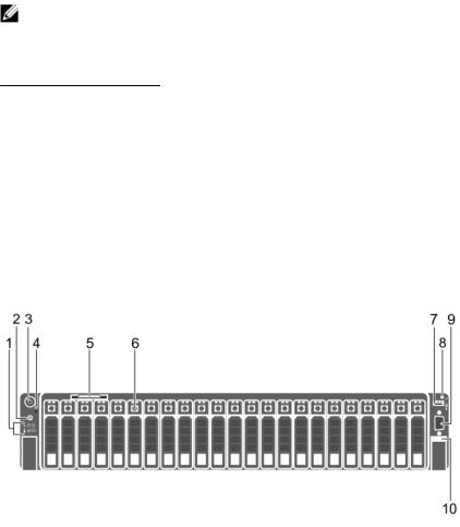
Front panel features and indicators
Figure 1. Front panel features and indicators (2.5 inch hard drive/SSD chassis)
8
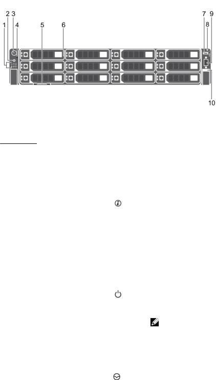
Figure 2. Front panel features and indicators (3.5 inch hard drive chassis)
Item |
Indicator, Button, or |
Icon |
Description |
|
Connector |
|
|
|
|
|
|
1 |
Diagnostic indicators |
|
The diagnostic indicators light up to display error |
|
|
|
status. |
|
|
|
For more information, see Diagnostic indicators. |
2System identification button
You can use the identification buttons on the front
— and back panels to locate a particular system within a rack. When one of these buttons is pressed, the system status indicator on the back flashes until one of the buttons is pressed again. Press to toggle the system ID on and off. If the system stops functioning during POST, press and hold the system ID button for more than five seconds to enter the BIOS progress mode. To reset iDRAC (if not disabled by entering iDRAC Setup mode by pressing ) press and hold the button for more than 15 seconds.
3 |
Power-on indicator, |
The power-on indicator lights when the system |
|
Power button |
power is on. The Power button controls the power |
|
|
supply output to the system. |
|
|
NOTE: On the Advanced Configuration and |
|
|
Power Interface (ACPI)-compliant operating |
|
|
systems (OSs), turning off the system by using |
|
|
the power button causes the system to |
|
|
perform a graceful shutdown before power to |
|
|
the system is disconnected. |
4 |
NMI button |
Use the Non-Maskable Interrupt (NMI) button to |
troubleshoot software and device driver errors while running certain OSs. Press the NMI button using the end of a paper clip
9

Item |
Indicator, Button, or |
Icon |
Description |
|
|
Connector |
|
|
|
|
|
|
|
|
|
|
|
Use the NMI button only if directed by qualified |
|
|
|
|
support personnel or by the OS's documentation |
|
|
|
|
. |
|
5 |
Information tag |
|
A slide-out label panel, which allows you to record |
|
|
|
|
system information such as Service Tag, NIC, MAC |
|
|
|
|
address. |
|
6 |
Hard drives |
|
2.5 inch hard |
Up to twenty four 2.5 inch |
|
|
|
||
|
|
|
drive/SSD |
hot-swappable hard drives. |
|
|
|
systems |
|
|
|
|
3.5 inch hard |
Up to twelve 3.5 inch hot- |
|
|
|
drive systems |
swappable hard drives. |
7USB management port/ iDRAC Direct
Allows you to connect USBdevices to the system or provides access to the iDRAC Direct features.For more information, see the Integrated Dell Remote Access ControllerUser’s Guide at dell.com/ esmmanuals. The USB management portis USB 2.0-compliant.
8 |
iDRAC Direct LED |
The indicator lights up to display error status. |
|
indicator |
|
9 |
Video connector |
Enables you to connect a display to the system. |
Diagnostic indicators
The diagnostic indicators on the system front panel display error status during system startup.
NOTE: The diagnostic indicators are not present if the system is equipped with an LCD display.
NOTE: The diagnostic indicators are present only on the 24–hard drive systems.
NOTE: No diagnostic indicators are lit when the system is switched off. To start the system, plug it into a working power source and press the Power button.
Table 1. Diagnostic indicators
Icon |
Description |
Condition |
Corrective action |
|
|
|
|
|
Health |
If the system is on, and in |
None required. |
|
indicator |
good health, the indicator |
|
|
|
lights solid blue. |
|
The indicator blinks amber if the system is on or in standby, and if any error exists (for example, a failed fan or hard drive).
See the System Event Log or system messages for the specific issue. For more information on error messages, see the Dell Event and Error Messages Reference Guide at dell.com/esmmanuals.
10
Icon |
Description Condition |
Corrective action |
Invalid memory configurations can cause the system to halt at startup without any video output. See Getting help.
Hard drive |
The indicator blinks amber if |
indicator |
a Hard drive experiences an |
|
error. |
See the System Event Log to determine the Hard drive that has an error. Run the appropriate Online Diagnostics test. Restart system and run embedded diagnostics (ePSA).
Electrical |
The indicator blinks amber if |
indicator |
the system experiences an |
|
electrical error (for example, |
|
voltage out of range, or a |
|
failed power supply or |
|
voltage regulator). |
Temperatur |
The indicator blinks amber if |
e indicator |
the system experiences a |
|
thermal error (for example, a |
|
temperature out of range or |
|
fan failure). |
Memory |
The indicator blinks amber if |
indicator |
a memory error occurs. |
See the System Event Log or system messages for the specific issue. If it is due to a problem with the power supply, check the LED on the power supply. Re-seat the power supply by removing and reinstalling it. If the problem persists, see Getting help.
Ensure that none of the following conditions exist:
•A cooling fan is removed or has failed.
•System cover, cooling shroud, EMI filler panel, memory-module blank, or backfiller bracket is removed.
•Ambient temperature is too high.
•External airflow is obstructed.
See Getting help.
See the system event log or system messages for the location of the failed memory. Reinstall the memory device. If the problem persists, see Getting help.
PCIe |
The indicator blinks amber if |
indicator |
a PCIe card experiences an |
|
error. |
Restart the system. Update any required drivers for the PCIe card. Re-install the card. If the problem persists, see Getting help.
NOTE: For more information on supported PCIe cards, see Expansion card installation guidelines.
11
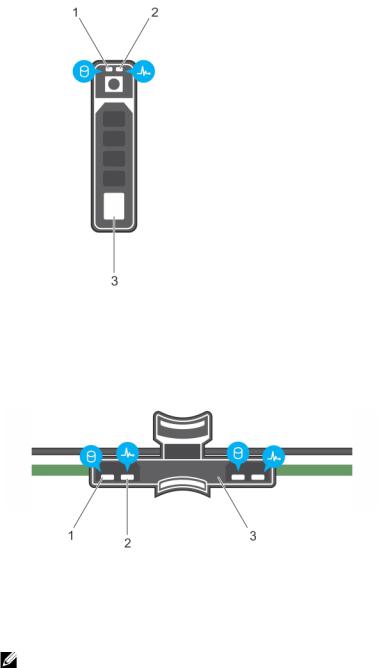
Hard drive indicator codes
Figure 3. Hard drive indicators
1. |
Hard drive activity indicator |
2. |
Hard drive status indicator |
3.Hard drive
Figure 4. HDD indicators on the hard-drive tray backplane
1. |
Hard drive activity indicator |
2. |
Hard drive status indicator |
3.Hard drive backplane on hard-drive tray
NOTE: If the Hard drive is in Advanced Host Controller Interface (AHCI) mode, the status indicator (on the right side) does not function and remains off.
12
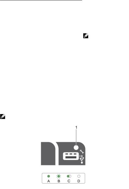
Table 2.
Drive-status indicator pattern |
Condition |
|
|
Blinks green two times per second |
Identifying drive or preparing for removal. HDD or SSD |
|
location is enabled or one of more HDDs or SSDs is in |
|
the failed state on the Nutanix Web GUI. |
Off |
Drive ready for insertion or removal. |
|
NOTE: The drive status indicator remains off until |
|
all hard drives are initialized after the system is |
|
turned on. Drives are not ready for insertion or |
|
removal during this time. |
Blinks green, amber, and turns off |
Predicted drive failure |
Blinks amber four times per second |
Drive failed |
Blinks green slowly |
Drive rebuilding |
Steady green |
Drive online |
Blinks green three seconds, amber three |
Rebuild aborted |
seconds, and turns off six seconds |
|
iDRAC Direct LED indicator codes
NOTE: The iDRAC Direct LED indicator does not light up for the USB mode.
Figure 5. iDRAC Direct LED indicator
1.iDRAC Direct status indicator
The table below displays iDRAC Direct activity when configuring iDRAC Direct by using the management port (USB XML Import).
13

Table 3. iDRAC Direct by using the management port (USB XML Import).
Convention |
iDRAC Direct |
Condition |
|
LED indicator |
|
|
pattern |
|
|
|
|
A |
Green |
Lights green for a minimum of 2 seconds at the beginning and end |
|
|
of a file transfer. |
B |
Flashing green |
Indicates file transfer or any operation tasks. |
C |
Green and turns |
Indicates that the file transfer is complete. |
|
off |
|
D |
Not lit |
Indicates that the USB is ready to be removed or that a task is |
|
|
complete. |
The table below displays iDRAC Direct activity when configuring iDRAC Direct using your laptop and cable (Laptop Connect).
Table 4. iDRAC Direct using your laptop and cable (Laptop Connect).
iDRAC Direct LED |
Condition |
indicator pattern |
|
|
|
Solid green for two |
Indicates that the laptop is connected. |
seconds |
|
Flashing green (on |
Indicates that the laptop connected is recognized. |
for two seconds and |
|
off for two seconds) |
|
Turns off |
Indicates that the laptop is unplugged. |
Back-panel features and indicators
Item |
Indicator, button, or |
Icon |
Description |
|
connector |
|
|
1System identification button
You can use the identification buttons on the front to locate a particular system within a rack. When one of these buttons is pressed, the system status indicator on the back flashes until one of the buttons is pressed again.
Press to toggle the system ID on and off. If the system stops responding during POST, press and hold the system ID button for more than five seconds to enter the BIOS progress mode.
14

Item |
Indicator, button, or |
Icon |
Description |
|
|
connector |
|
|
|
|
|
|
|
|
|
|
|
To reset iDRAC (if not disabled in F2 |
|
|
|
|
iDRAC setup) press and hold the button |
|
|
|
|
for more than 15 seconds. |
|
2 |
System identification |
|
Connects the optional system status |
|
|
connector |
|
indicator assembly through the optional |
|
|
|
|
cable management arm. |
|
3 |
iDRAC8 Enterprise port |
|
Dedicated management port for |
|
|
|
|
iDRAC8. |
|
4 |
Half-height PCIe |
|
Allows you to connect up to three half- |
|
|
expansion-card slot (3) |
|
height PCI Express expansion cards. |
|
5 |
Serial connector |
|
Allows you to connect a serial device to |
|
|
|
|
the system. |
|
6 |
Video connector |
|
Allows you to connect a VGA display to |
|
|
|
|
the system. |
|
7 |
USB connector (2) |
|
Allows you to connect USB devices to |
|
|
|
|
the system. The ports are USB 3.0- |
|
|
|
|
compliant. |
|
8 |
Full-height PCIe |
|
Allows you to connect up to three full- |
|
|
expansion-card slot (3) |
|
height PCI Express expansion cards. |
|
|
|
|
These are reserved for Dell PERC H310 |
|
|
|
|
and LSI 9207-8i. |
|
9 |
Ethernet connector (4) |
|
Four integrated 10/100/1000 Mbps NIC |
|
|
|
|
connectors |
|
|
|
|
or |
|
|
|
|
Four integrated connectors that include: |
|
|
|
|
• Two 10/100/1000 Mbps NIC |
|
|
|
|
connectors |
|
|
|
|
• Two 100 Mbps/1 Gbps/10 Gbps SFP |
|
|
|
|
+/10 GbE T connectors |
|
10 |
Power supply unit (PSU1) |
|
AC |
495 W, 750 W, or |
|
|
|
||
11 |
Power supply unit |
|
|
1100 W |
|
(PSU2) |
|
DC |
495 W, 750 W, or |
|
|
|
||
|
|
|
|
1100 W |
12 |
vFlash media card slot |
|
Allows you to insert a vFlash media card. |
|
13 |
Two HDD blanks |
|
|
|
15
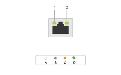
NIC indicator codes
Figure 6. NIC indicators |
|
|
|
|
1. |
link indicator |
2. |
activity indicator |
|
|
|
|
|
|
|
|
Indicator |
|
Indicator code |
|
|
|
|
|
A |
|
Link and activity indicators are off |
The NIC is not connected to the |
|
|
|
|
|
network. |
B |
|
Link indicator is green |
|
The NIC is connected to a valid |
|
|
|
|
network at its maximum port |
|
|
|
|
speed (1 Gbps or 10 Gbps). |
C |
|
Link indicator is amber |
|
The NIC is connected to a valid |
|
|
|
|
network at less than its maximum |
|
|
|
|
port speed. |
D |
|
Activity indicator is blinking green |
Network data is being sent or |
|
|
|
|
|
received. |
Power indicator codes
Each AC power supply unit (PSU) has an illuminated translucent handle and each DC power supply unit (when available) has an LED that serves as an indicator to show whether power is present or a power fault has occurred.
16
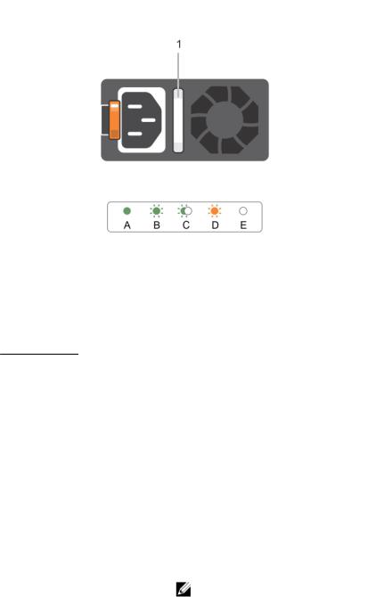
Figure 7. AC power supply unit status indicator
1. AC power supply unit status indicator/handle
Table 5. AC Power indicator
Convention |
Power indicator |
Condition |
|
pattern |
|
|
|
|
A |
Green |
The handle indicator lights green indicating that a valid power |
|
|
source is connected to the power supply unit and that the power |
|
|
supply unit is operational. |
B |
Flashing green |
When updating the firmware of the power supply unit, the power |
|
|
supply unit handle flashes green. |
C |
Flashing green |
When hot-adding a power supply unit (PSU), the power supply unit |
|
and turns off |
handle flashes green five times at 4 Hz rate and turns off. This |
|
|
indicates that the power supply unit is mismatched with the other |
|
|
power supply unit (in terms of efficiency, feature set, health status, |
|
|
and supported voltage). Replace the power supply unit that has the |
|
|
flashing indicator with a power supply unit that matches the capacity |
|
|
of the other installed power supply unit. |
|
|
NOTE: For AC power supplies, use only PSUs with the Extended |
|
|
Power Performance (EPP) label on the back. Mixing PSUs from |
|
|
previous generations of servers can result in a PSU mismatch |
|
|
condition or failure to power on. |
D |
Flashing amber |
Indicates a problem with the power supply unit. |
17
Convention |
Power indicator |
Condition |
|
pattern |
|
|
|
|
|
|
CAUTION: When correcting a power supply unit mismatch, |
|
|
replace only the power supply unit with the flashing indicator. |
|
|
Swapping the opposite power supply unit to make a matched |
|
|
pair can result in an error condition and unexpected system |
|
|
shutdown. To change from a High Output configuration to a |
|
|
Low Output configuration or vice versa, you must power |
|
|
down the system. |
|
|
CAUTION: AC power supplies support both 220 V and 110 V |
|
|
input voltages with the exception of Titanium power supplies, |
|
|
which support only 220 V. When two identical power supplies |
|
|
receive different input voltages, they can output different |
|
|
wattages, and trigger a mismatch. |
|
|
CAUTION: If two power supplies are used, they must be of the |
|
|
same type and have the same maximum output power. |
|
|
CAUTION: Combining AC and DC power supplies is not |
|
|
supported and triggers a mismatch. |
E |
Not lit |
Power is not connected. |
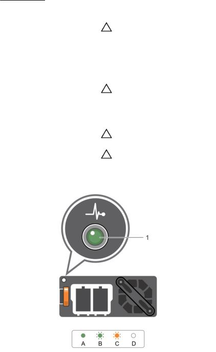
Figure 8. DC power supply unit status indicator
1.DC power supply unit status indicator
18

Table 6. DC Power indicator
Convention |
Power indicator |
Condition |
|
pattern |
|
|
|
|
A |
Green |
The handle/LED indicator lights green indicating that a valid power |
|
|
source is connected to the power supply unit and that the power |
|
|
supply unit is operational. |
B |
Flashing green |
When hot-adding a power supply unit, power supply unit LED |
|
|
flashes green. This indicates that the power supply unit is |
|
|
mismatched with the other power supply unit (in terms of |
|
|
efficiency, feature set, health status, and supported voltage). |
|
|
Replace the power supply unit that has the flashing indicator with a |
|
|
power supply unit that matches the capacity of the other installed |
|
|
power supply unit. |
C |
Flashing amber |
Indicates a problem with the power supply unit. |
|
|
CAUTION: When correcting a power supply unit mismatch, |
|
|
replace only the power supply unit with the flashing |
|
|
indicator. Swapping the opposite power supply unit to make |
|
|
a matched pair can result in an error condition and |
|
|
unexpected system shutdown. To change from a High |
|
|
Output configuration to a Low Output configuration or vice |
|
|
versa, you must power down the system. |
|
|
CAUTION: AC power supplies support both 220 V and 110 V |
|
|
input voltages with the exception of Titanium power |
|
|
supplies, which support only 220 V. When two identical |
|
|
power supplies receive different input voltages, they can |
|
|
output different wattages, and trigger a mismatch. |
|
|
CAUTION: If two power supplies are used, they must be of |
|
|
the same type and have the same maximum output power. |
|
|
CAUTION: Combining AC and DC power supplies is not |
|
|
supported and triggers a mismatch. |
D |
Not lit |
Power is not connected. |
Documentation matrix
The documentation matrix provides information about the documents you use to configure and deploy the Dell web-scale converged appliance solution.
WARNING: See the safety and regulatory information that shipped with your system. Warranty information may be included with this document or as a separate document.
Make sure that you read through any media that ships with your system that provides documentation and tools for configuring and managing your system, including those pertaining to the OS, system management software, system updates, and system components that you purchased with your system.
NOTE: URLs such as dell.com/support or dell.com/support/home are not active, because you must type the URL from your location to access your specific language.
19

For the full name of an abbreviation or acronym used in this document, see the Glossary at dell.com/ support/home.
NOTE: Always check for updates on dell.com/support/home and read through the updates first, because they often supersede information in other documents.
NOTE: While upgrading your system, it is recommended that you download and install the latest BIOS, driver, and systems management firmware on your system from dell.com/support.
The following tables list the documents provided by Dell and Nutanix.
Dell documentation
Dell documentation is either included with your shipment or available at the Dell website at dell.com/ xcseriesmanuals.
Dell documentation for:
•Dell iDRAC is available at dell.com/esmmanuals.
•Dell OpenManage Essentials is available at dell.com/openmanagemanuals.
To access Dell documentation:
1.On the Dell Support page, scroll down to General Support, and then click Servers, Storage & Networking.
2.Click Engineered Solutions and select the documentation you require.
Table 7. Dell reference documentation for the Dell XC730xd Web-scale Converged Appliance
To learn about… |
Refer to… |
|
|
Setup instructions of your Dell XC730xd, including |
Getting Started Guide |
the technical specifications |
|
Hardware details of your Dell XC730xd |
Owner’s Manual |
How to install your Dell XC730xd in a rack |
Dell Rack Install Guide |
How to deploy and set up this solution |
Solutions Guide |
Setting up and using Dell iDRAC 8 |
Dell iDRAC 8 Quick Start Guide |
Using OpenManage Essentials to monitor, perform |
Dell OpenManage Essentials User’s Guide |
updates, view hardware, and view inventory on |
|
your system |
|
Nutanix documentation
Most Nutanix documentation is available at https://portal.nutanix.com/#/page/docs on the Nutanix Documents page. However, two documents are available behind the Nutanix document portal. Nutanix documentation is listed by version, category, and type. Make sure that you select the appropriate version of documentation for this release, which is 4.0 or later. Or refer to the Nutanix OS to find corresponding documentation support.
To access most Nutanix documentation:
20
1.Go to https://portal.nutanix.com/#/page/docs.
2.Select the documentation you require from the list specified in Table 10.
NOTE: To access the Hardware Replacement Documentation using the open document portal, use the Filter By controls in the upper right corner of the page. Select NOS, 4.x, and XC730xd to display this document.
To access the NOS Advanced Administration Guide and Advanced Setup Guide:
1.Go to https://portal.nutanix.com/#login.
2.Log in to your portal and select Documentation.
3.On the Nutanix Documents page, select the documentation you require.
Table 8. Nutanix reference documentation
To learn about… |
Refer to… |
|
|
Setup instructions for your solution. |
Setup Guide |
Setup instructions for environments with special |
Advanced Setup Guide |
requirements and restrictions |
|
Instructions and reference for administering the |
NOS Advanced Administration Guide |
Nutanix Operation System (NOS) outside the |
|
Nutanix Prism UI (such as cluster start/stop, |
|
manual upgrade, changing passwords, |
|
reconfiguring IP addresses, and troubleshooting |
|
tools). |
|
Comprehensive instructions and references for the |
Web Console Guide |
Nutanix UI, including overview information. |
|
Managing VMware ESXi hosts that run NOS, |
vSphere Administration Guide |
including VMware vCenter requirements. |
|
Managing Hyper-V hosts that run NOS. |
Hyper-V Administration Guide |
Comprehensive references for the Nutanix REST |
API Reference |
API. |
|
Comprehensive references for Controller Virtual |
Command Reference |
Machine (CVM) utilities, nCLI commands, and |
|
Nutanix PowerShell cmdlets. |
|
Software instructions for hardware components |
Hardware Replacement Documentation |
that are not functioning. |
|
Quick Resource Locator
Use the Quick Resource Locator (QRL) to get immediate access to system information and how-to videos. This can be done by visiting dell.com/QRL or by using your smartphone or tablet and a model specific Quick Resource (QR) code located on your Dell system. To try out the QR code, scan the following image.
21

Figure 9. Quick Resource Locator
22
2
Performing initial system configuration
After you receive your system, you must set up your system, install the operating system if it is not preinstalled, and set up and configure the system iDRAC IP address.
Setting up your system
1.Unpack the server.
2.Install the server into the rack. For more information on installing the server into the rack, see your system Rack Installation Placemat at dell.com/xcseriesmanuals.
3.Connect the peripherals to the system.
4.Connect the system to its electrical outlet.
5.Turn the system on by pressing the Power button or using iDRAC.
6.Turn on the attached peripherals.
Methods of setting up and configuring the iDRAC IP address
You can set up the Integrated Dell Remote Access Controller (iDRAC) IP address by using one of the following interfaces:
•iDRAC Settings utility.
•Lifecycle Controller.
•Dell Deployment Toolkit.
•Server LCD panel.
You can configure iDRAC IP using:
1.iDRAC Web Interface.
For more information on setting up and configuring iDRAC, see the Integrated Dell Remote Access Controller User's Guide at dell.com/esmmanuals.
2.Remote Access Controller ADMin (RACADM).
For more information, see the RACADM Command Line Interface Reference Guide and the Integrated Dell Remote Access Controller User's Guide.
3.Remote Services that includes Web Services Management (WS-Man). For more information, see the
Lifecycle Controller Remote Services Quick Start Guide.
Logging in to iDRAC
You can log in to iDRAC as an iDRAC local user, a Microsoft Active Directory user, or a Lightweight Directory Access Protocol (LDAP) user. You can also log in by using Single Sign-On or a Smart Card. The
23

default user name is root and password is calvin. For more information on logging in to iDRAC and iDRAC licenses, see the Integrated Dell Remote Access Controller User's Guide at dell.com/esmmanuals.
You can also access iDRAC using RACADM. For more information, see the RACADM Command Line Interface Reference Guide and the Integrated Dell Remote Access Controller User's Guide available at dell.com/esmmanuals.
Installing the operating system
If the server is shipped without an operating system, install the supported operating system on the server by using one of the following methods:
•Dell Systems Management Tools and Documentation media. See the operating system documentation at dell.com/operatingsystemmanuals.
•Dell Lifecycle Controller. See the Lifecycle Controller documentation at dell.com/esmmanuals.
•Dell OpenManage Deployment Toolkit. See the OpenManage documentation at dell.com/ openmanagemanuals.
For information on the list of operating systems supported on your system, see the operating systems support matrix at dell.com/ossupport.
Remote management
To perform out-of-band systems management using iDRAC, you must configure iDRAC for remote accessibility, set up the management station and managed system, and configure the supported Web browsers. For more information, see the Integrated Dell Remote Access Controller User’s Guide at dell.com/esmmanuals.
You can also remotely monitor and manage the server by using the Dell OpenManage Server Administrator software and OpenManage Essentials systems management console. For more information, see dell.com/openmanagemanuals.
Downloading and installing drivers and firmware
Dell recommends that you download and install the latest BIOS, drivers, and systems management firmware on your system.
Prerequisites
Ensure that you clear the web browser cache.
Steps
1.Go to Support.Dell.com.
2.Under Support in the Customized support section type your Service Tag into the Enter your Service Tag or Express Service code box.
NOTE: If you do not have the Service Tag, select Detect My Product to allow the system to automatically detect your Service Tag, or under General support select your product page.
3.Click Drivers & downloads.
The drivers that are applicable to your selection are displayed.
4.Download the drivers you require to a diskette drive, USB drive, CD, or DVD.
24

3
Pre-operating system management applications
The pre-operating system management applications for your system helps you manage different settings and features of your system without booting to the operating system.
Your system has the following pre-operating system management applications:
•System Setup
•Boot Manager
•Dell Lifecycle Controller
Dell Lifecycle Controller allows you to perform useful tasks such as configuring BIOS and hardware settings, deploying operating system, updating drivers, and saving hardware profiles. For more information about Dell Lifecycle Controller, see the documentation at dell.com/esmmanuals.
Navigation keys
The navigation keys can help you access the pre-operating system management applications.
Table 9. Navigation keys
Key |
Description |
|
|
Page Up |
Moves to the previous screen. |
Page Down |
Moves to the next screen. |
Up arrow |
Moves to the previous field. |
Down |
Moves to the next field. |
arrow |
|
Enter |
Enables you to type a value in the selected field (if applicable) or follow the link in the field. |
Spacebar |
Expands or collapses a drop-down list, if applicable. |
Tab |
Moves to the next focus area. |
|
NOTE: This feature is applicable for the standard graphical browser only. |
Esc |
Moves to the previous page until you view the main screen. Pressing Esc in the main |
|
screen exits System BIOS/iDRAC Settings/Device Settings/Service Tag Settings and |
|
proceeds with system boot. |
F1 |
Displays the System Setup help. |
F2 |
Enables you to enter System Setup |
25

Key |
Description |
|
|
F10 |
Enables you to enter Lifecycle Controller |
F11 |
Enables you to enter Boot Manager |
F12 |
Enables you to enter PXE boot |
About System Setup
Using System Setup, you can configure the BIOS settings, iDRAC settings, and device settings of your system.
NOTE: There are a several generic server settings that appear during system setup that do not apply to this system, such as RAID or UEFI.
You can access System Setup in two ways:
•Standard Graphical Browser — This is enabled by default.
•Text Browser — This is enabled using Console Redirection. To enable Console Redirection:
•On the System Setup page, click System BIOS.
•On the Serial Communications page, click Serial Communication, and then select On with Console Redirection.
NOTE: By default, help text for the selected field is displayed in the graphical browser. To view the help text in the text browser, press F1.
From System Setup, you can:
•Change the NVRAM settings after you add or remove hardware
•View the system hardware configuration
•Enable or disable integrated devices
•Set performance and power management thresholds
•Manage system security
Entering System Setup
1.Turn on or restart your system.
2.Press F2 immediately after you see the following message:
<F2> = System Setup
If your operating system begins to load before you press F2, allow the system to finish booting, and then restart your system and try again.
NOTE: If an error message is displayed while the system is starting, make a note of the message. For more information, see System messages.
NOTE: After installing a memory upgrade, it is normal for your system to display a message the first time you start your system.
26

System Setup Main Menu
Table 10. System setup main menu
Option |
Description |
|
|
System BIOS |
Enables you to configure BIOS settings. |
iDRAC Settings |
Enables you to configure iDRAC settings. |
|
The iDRAC Settings utility is an interface to set up and configure the |
|
iDRAC parameters by using UEFI. You can enable or disable various |
|
iDRAC parameters by using the iDRAC Settings utility. For more |
|
information about this utility, see the Integrated Dell Remote Access |
|
Controller User’s Guide at dell.com/esmmanuals. |
Device Settings |
Enables you to configure device settings. |
Editing system BIOS screen settings
You can use the System BIOS screen to view the BIOS settings. You can also edit some of the settings such as Boot Order, System Password, Setup Password, and enable or disable USB ports.
Go to System Setup Main Menu, and then click System BIOS.
The System BIOS screen is displayed.
System BIOS screen settings
The System BIOS screen details are explained below.
Table 11. System BIOS
Menu Item |
Description |
|
|
System Information |
Displays information about the system such as the system model name, |
|
BIOS version and Service Tag. |
Memory Settings |
Displays information and options related to the installed memory. |
Processor Settings |
Displays information and options related to the processor such as speed, |
|
cache size, and so on. |
SATA Settings |
Displays options to enable or disable the integrated SATA controller and |
|
ports. |
Boot Settings |
Displays options to specify the boot mode (BIOS or UEFI). Enables you to |
|
modify UEFI and BIOS boot settings. |
Network Settings |
Displays options to change the network settings. |
Integrated Devices |
Displays options to enable or disable integrated device controllers and |
|
ports, and to specify related features and options. |
Serial Communication |
Displays options to enable or disable the serial ports and specify related |
|
features and options. |
System Profile Settings |
Displays options to change the processor power management settings, |
|
memory frequency, and so on. |
System Security |
Displays options to configure the system security settings like, system |
|
password, setup password, Trusted Platform Module (TPM) security, and |
27

Menu Item |
Description |
|
|
|
so on. It also enables or disables support for the power and NMI buttons |
|
on the system. |
Miscellaneous Settings |
Displays options to change the system date, time, and so on. |
Editing system information
You can use the System Information screen to view system properties such as Service Tag, system model, and the BIOS version.
1.Go to System Setup Main Menu, and then click System BIOS.
2.On System BIOS, click System Information. The System Information screen is displayed.
System information screen settings
The System Information screen details are explained as follows:
Table 12. System information
Menu Item |
Description |
|
|
System Model Name |
Displays the system model name. |
System BIOS Version |
Displays the BIOS version installed on the system. |
System Management |
Displays the current revision of the Management Engine firmware. |
Engine Version |
|
System Service Tag |
Displays the system Service Tag. |
System Manufacturer |
Displays the name of the system manufacturer. |
System Manufacturer |
Displays the contact information of the system manufacturer. |
Contact Information |
|
System CPLD Version |
Displays the current revision of the system CPLD firmware. |
UEFI Compliance Version |
Displays the system firmware UEFI compliance level. |
Editing memory settings
You can use the Memory Settings screen to view all the memory settings. You can also enable or disable some memory configurations such as system memory testing and node interleaving.
1.Go to System Setup Main Menu, and then click System BIOS.
2.On System BIOS, click Memory Settings. The Memory Settings screen displays..
Memory screen settings
The Memory Settings screen details are explained as follows:
28

Table 13. Memory settings
Menu Item |
Description |
|
|
System Memory Size |
Displays the amount of memory installed in the system. |
System Memory Type |
Displays the type of memory installed in the system. |
System Memory Speed |
Displays the system memory speed. |
System Memory Voltage |
Displays the system memory voltage. |
Video Memory |
Displays the amount of video memory. |
System Memory Testing |
Specifies whether system memory tests are run during system boot. |
|
Options are Enabled and Disabled. By default, the System Memory |
|
Testing option is set to Disabled. |
Memory Operating Mode |
Specifies the memory operating mode. The options available are |
|
Optimizer Mode, Advanced ECC Mode, Mirror Mode, Spare Mode, |
|
Spare with Advanced ECC Mode, and Dell Fault Resilient Mode. By |
|
default, the Memory Operating Mode option is set to Optimizer Mode. |
|
NOTE: The Memory Operating Mode can have different defaults |
|
and available options based on the memory configuration of your |
|
system. |
|
NOTE: The Dell Fault Resilient Mode establishes an area of memory |
|
that is fault resilient. This mode can be used by an operating system |
|
that supports the feature to load critical applications or enables the |
|
operating system kernel to maximize system availability. |
Node Interleaving |
Specifies if Non-Uniform Memory architecture (NUMA) is supported. If |
|
this field is Enabled, memory interleaving is supported if a symmetric |
|
memory configuration is installed. If Disabled, the system supports |
|
NUMA (asymmetric) memory configurations. By default, Node |
|
Interleaving option is set to Disabled. |
Snoop Mode |
Specifies the Snoop Mode options. Snoop Mode options available are |
|
Home Snoop, Early Snoop, Cluster on Die. By default, the Snoop Mode |
|
option is set to Early Snoop. The field is only available when Node |
|
Interleaving is Disabled. |
Editing processor settings
You can use the Processor Settings screen to view the processor settings. You can also enable virtualization technology, hardware prefetcher, and logical processor idling.
1.Go to System Setup Main Menu, and then click System BIOS.
2.On System BIOS, click Processor Settings. The Processor Settings screen displays.
Processor settings screen
The Processor Settings screen details are explained as follows:
29

Table 14. Processor settings
Menu Item |
Description |
|
|
Logical Processor |
Enables or disables the logical processors and displays the number of |
|
logical processors. If the Logical Processor option is set to Enabled, the |
|
BIOS displays all the logical processors. If this option is set to Disabled, |
|
the BIOS only displays one logical processor per core. By default, the |
|
Logical Processor option is set to Enabled. |
Alternate RTID (Requestor |
Enables you to allocate more RTIDs to the remote socket, thereby |
Transaction ID) Setting |
increasing cache performance between the sockets or easing work in |
|
normal mode for NUMA. By default, the Alternate RTID (Requestor |
|
Transaction ID) Setting is set to Disabled. |
Virtualization Technology |
Enables or disables the additional hardware capabilities provided for |
|
virtualization. By default, the Virtualization Technology option is set to |
|
Enabled. |
Address Translation Service |
Defines the Address Translation Cache (ATC) for devices to cache the |
(ATS) |
DMA transactions. This field provides an interface to a chipset's Address |
|
Translation and Protection Table to translate DMA addresses to host |
|
addresses. By default, the option is set to Enabled. |
Adjacent Cache Line |
Optimizes the system for applications that require high usage of |
Prefetch |
sequential memory access. By default, the Adjacent Cache Line Prefetch |
|
option is set to Enabled. You can disable this option for applications that |
|
require high usage of random memory access. |
Hardware Prefetcher |
Enables or disables the hardware prefetcher. By default, the Hardware |
|
Prefetcher option is set to Enabled. |
DCU Streamer Prefetcher |
Allows you to enable or disable the Data Cache Unit (DCU) streamer |
|
prefetcher. By default, the DCU Streamer Prefetcher option is set to |
|
Enabled. |
DCU IP Prefetcher |
Enables or disables the Data Cache Unit (DCU) IP prefetcher. By default, |
|
the DCU IP Prefetcher option is set to Enabled. |
Execute Disable |
Enables or disables the execute disable memory protection technology. |
|
By default, the Execute Disable option is set to Enabled. |
Logical Processor Idling |
Enables or disables the operating system capability to put logical |
|
processors in the idling state in order to reduce power consumption. By |
|
default, the option is set to Disabled. |
Configurable TDP |
Allows reconfiguration of Thermal Design Power (TDP) to lower levels. |
|
TDP refers to the maximum amount of power the cooling system is |
|
required to dissipate. |
X2Apic Mode |
Enables or disables the X2Apic mode. |
Dell Controlled Turbo |
NOTE: Depending on the number of installed CPUs, there may be |
|
|
|
up to four processor listings. |
|
Controls the turbo engagement. Enable this option only when System |
|
Profile is set to Performance. |
Number of Cores per |
Controls the number of enabled cores in each processor. By default, the |
Processor |
Number of Cores per Processor option is set to All. |
Processor 64-bit Support |
Specifies if the processor(s) support 64-bit extensions. |
30
Loading...