


 Loading...
Dell™ OptiPlex™ SX280
Quick Reference Guide
Model DCTR
w w w . d e l l . c o m | s u p p o r t . d e l l . c o m

Notes, Notices, and Cautions
NOTE: A NOTE indicates important information that helps you make better use of your computer.
NOTICE: A NOTICE indicates either potential damage to hardware or loss of data and tells you how to avoid the problem.
 CAUTION: A CAUTION indicates a potential for property damage, personal injury, or death.
If you purchased a Dell™ n Series computer, any references in this document to Microsoft® Windows® operating systems are not applicable.
Information in this document is subject to change without notice. © 2004 Dell Inc. All rights reserved.
Reproduction in any manner whatsoever without the written permission of Dell Inc. is strictly forbidden.
Trademarks used in this text: Dell, OptiPlex, and the DELL logo are trademarks of Dell Inc.; Microsoft and Windows are registered trademarks of Microsoft Corporation.
Other trademarks and trade names may be used in this document to refer to either the entities claiming the marks and names or their products. Dell Inc. disclaims any proprietary interest in trademarks and trade names other than its own.
Model DCTR
April 2004 |
P/N X2956 |
Rev. A00 |

Contents
Finding Information . . . . . . . . . . . . . . . . . . . . . . . . . . . . |
5 |
About Your Computer . . . . . . . . . . . . . . . . . . . . . . . . . . . |
8 |
Front View . . . . . . . . . . . . . . . . . . . . . . . . . . . . . . |
8 |
Side View. . . . . . . . . . . . . . . . . . . . . . . . . . . . . . . |
8 |
Back View . . . . . . . . . . . . . . . . . . . . . . . . . . . . . . |
9 |
Cable Cover and Power Adapter . . . . . . . . . . . . . . . . . . . . |
9 |
Setting Up Your Computer . . . . . . . . . . . . . . . . . . . . . . . . . |
10 |
Determining Placement and Orientation of the Computer . . . . . . . . |
10 |
Installing a Device in the Module Bay . . . . . . . . . . . . . . . . . |
11 |
Connecting External Devices . . . . . . . . . . . . . . . . . . . . . |
12 |
Installing a Hard Drive. . . . . . . . . . . . . . . . . . . . . . . . . |
15 |
Attaching the Optional Cable Cover . . . . . . . . . . . . . . . . . . |
16 |
Inside Your Computer . . . . . . . . . . . . . . . . . . . . . . . . . . . |
16 |
Removing the Computer Cover . . . . . . . . . . . . . . . . . . . . . |
16 |
Inside View . . . . . . . . . . . . . . . . . . . . . . . . . . . . . . |
17 |
Replacing the Computer Cover. . . . . . . . . . . . . . . . . . . . . |
18 |
Solving Problems . . . . . . . . . . . . . . . . . . . . . . . . . . . . . |
18 |
Dell Diagnostics. . . . . . . . . . . . . . . . . . . . . . . . . . . . |
19 |
Power Supply Light . . . . . . . . . . . . . . . . . . . . . . . . . . |
22 |
System Lights . . . . . . . . . . . . . . . . . . . . . . . . . . . . . |
22 |
Diagnostic Lights . . . . . . . . . . . . . . . . . . . . . . . . . . . |
23 |
Beep Codes. . . . . . . . . . . . . . . . . . . . . . . . . . . . . . |
26 |
Running the Dell™ IDE Hard Drive Diagnostics . . . . . . . . . . . . . |
27 |
Resolving Software and Hardware Incompatibilities . . . . . . . . . . |
27 |
Using Microsoft® Windows® XP System Restore . . . . . . . . . . . . |
28 |
Reinstalling Microsoft® Windows® XP . . . . . . . . . . . . . . . . . |
29 |
Using the Drivers and Utilities CD . . . . . . . . . . . . . . . . . . . . . |
32 |
Index . . . . . . . . . . . . . . . . . . . . . . . . . . . . . . . . . . . . |
33 |
Contents 3

4 Contents
Finding Information
What Are You Looking For? |
Find It Here |
|
|
• A diagnostic program for my computer |
Drivers and Utilities CD (also known as the ResourceCD) |
• Drivers for my computer |
Documentation and drivers are already installed on your |
• My computer documentation |
computer. You can use the CD to reinstall drivers, run the |
• My device documentation |
Dell Diagnostics, or access your documentation. |
• Desktop System Software (DSS) |
Readme files may be |
|
included on your CD |
|
to provide last-minute |
|
updates about technical |
|
changes to your |
|
computer or advanced |
|
technical-reference |
|
material for technicians |
|
or experienced users. |
|
NOTE: The latest drivers |
|
and documentation |
|
updates can be found at support.dell.com. |
|
|
• OS updates and patches |
Desktop System Software (DSS) |
|
Located on the Drivers and Utilities CD and at |
|
support.dell.com. |
|
|
• Warranty information |
Dell™ Product Information Guide |
• Safety instructions |
|
• Regulatory information |
|
• Ergonomics information |
|
• End User License Agreement |
|
|
NOTE: This document is available as a PDF at |
|
|
support.dell.com. |
|
|
|
|
• How to remove and replace parts |
Dell OptiPlex™ User’s Guide |
|
• Technical specifications |
Microsoft® Windows® XP Help and Support Center |
|
• How to configure system settings |
1 |
Click the Start button and click Help and Support. |
• How to troubleshoot and solve problems |
2 |
Click User’s and system guides and click User’s guides. |
The User’s Guide is also available on the Drivers and
Utilities CD.
Quick Reference Guide |
5 |

w w w . d e l l . c o m | s u p p o r t . d e l l . c o m
What Are You Looking For? |
Find It Here |
|
|
• Service Tag and Express Service Code |
Service Tag and Microsoft Windows License |
• Microsoft Windows License Label |
These labels are located on your computer. |
|
• Use the Service Tag to |
|
identify your |
|
computer when you |
|
use support.dell.com |
|
or contact technical |
|
support. |
|
• Enter the Express |
|
Service Code to direct your call when contacting |
|
technical support. The Express Service Code is not |
|
available in all countries. |
|
|
• Latest drivers for my computer |
Dell Support Website — support.dell.com |
• Answers to technical service and support questions |
NOTE: Select your region to view the appropriate support |
• Online discussions with other users and technical |
site. |
support |
The Dell Support website provides several online tools, |
• Documentation for my computer |
including: |
|
• Solutions — Troubleshooting hints and tips, articles |
|
from technicians, and online courses |
|
• Community — Online discussion with other Dell |
|
customers |
|
• Upgrades — Upgrade information for components, such |
|
as memory, the hard drive, and the operating system |
|
• Customer Care — Contact information, order status, |
|
warranty, and repair information |
|
• Downloads — Drivers, patches, and software updates |
|
• Reference — Computer documentation, product |
|
specifications, and white papers |
|
|
• Service call status and support history |
Dell Premier Support Website — premiersupport.dell.com |
• Top technical issues for my computer |
The Dell Premier Support website is customized for |
• Frequently asked questions |
corporate, government, and education customers. This |
• File downloads |
website may not be available in all regions. |
• Details on my computer configuration |
|
• Service contract for my computer |
|
6 Quick Reference Guide
What Are You Looking For? |
Find It Here |
|
|
• How to use Windows XP |
Windows Help and Support Center |
• Documentation for my computer |
1 Click the Start button and click Help and Support. |
• Documentation for devices (such as a modem) |
2 Type a word or phrase that describes your problem |
|
and click the arrow icon. |
|
3 Click the topic that describes your problem. |
|
4 Follow the instructions on the screen. |
|
|
• How to reinstall my operating system |
Operating System CD |
|
The operating system is already installed on your |
|
computer. To reinstall your operating system, use the |
|
Operating System CD. See your OptiPlex User’s Guide |
|
for instructions. |
|
After you reinstall your |
|
operating system, use the |
|
Drivers and Utilities CD |
|
to reinstall drivers for the |
|
devices that came with |
|
your computer. |
|
Your operating system |
|
product key is located on |
|
your Windows License |
|
label attached to your |
|
computer. |
|
NOTE: The color of your CD varies based on the operating |
|
system you ordered. |
|
|
• Regulatory Model Number |
DCTR |
• Chassis Type |
Ultra-Small Form-Factor (USFF) chassis |
|
|
Quick Reference Guide |
7 |
w w w . d e l l . c o m | s u p p o r t . d e l l . c o m
About Your Computer
NOTE: If you want to orient your computer under a desk top or on a wall surface, use the optional wallmount bracket. To order the bracket, contact Dell. For information on contacting Dell, see your online
User’s Guide.
NOTE: To ensure proper ventilation, do not block the cooling vents.
Front View
microphone connector |
|
|
|
|
|
|
|
|
power light |
||||||||||||||||||||||||||||||||||||||||||||
USB connectors (2) |
|
|
|
|
|
|
|
|
|
|
|
power button |
|||||||||||||||||||||||||||||||||||||||||
|
|
|
|
|
|
|
|
|
|
|
|
|
|
|
|
|
|
|
|
|
|
|
|
|
|
|
|
|
|
|
|
|
|
|
|
|
|
|
|
|
|
|
|
|
|
|
|
|
|
|
|
|
|
|
|
|
|
|
|
|
|
|
|
|
|
|
|
|
|
|
|
|
|
|
|
|
|
|
|
|
|
|
|
|
|
|
|
|
|
|
|
|
|
|
|
|
|
|
|
|
|
|
|
|
|
|
|
|
|
|
|
|
|
|
|
|
|
|
|
|
|
|
|
|
|
|
|
|
|
|
|
|
|
|
|
|
|
|
|
|
|
|
|
|
|
|
|
|
|
|
|
|
|
|
|
|
|
|
|
|
|
|
|
|
|
|
|
|
|
|
|
|
|
|
|
|
|
|
|
|
|
|
|
|
|
|
|
|
|
|
|
|
|
|
|
|
|
|
|
|
|
|
|
|
|
|
|
|
|
|
|
|
|
|
|
|
|
|
|
|
|
|
|
|
|
|
|
|
|
|
|
|
|
|
|
|
|
|
|
|
|
|
|
|
|
|
|
|
|
|
|
|
|
|
|
|
|
|
|
|
|
|
|
|
|
|
|
|
|
|
|
|
|
|
|
|
|
|
|
|
|
|
|
|
|
|
|
|
|
|
|
|
|
|
|
|
|
|
|
|
|
|
|
|
|
|
|
|
|
|
|
|
|
|
|
|
|
|
|
|
|
|
|
|
|
|
|
|
|
|
|
|
|
|
|
|
|
|
|
|
|
|
|
|
|
|
|
|
|
|
|
|
|
|
|
|
|
|
|
|
|
|
|
|
|
|
|
|
|
|
|
|
|
|
|
|
|
|
|
|
|
|
|
|
|
|
|
|
|
|
|
|
|
|
|
|
|
|
|
|
|
|
|
|
|
|
|
|
|
|
|
|
|
|
|
|
|
|
|
|
|
|
|
|
|
|
|
|
|
|
|
|
|
|
|
|
|
|
|
|
|
|
|
|
|
|
|
|
|
|
|
|
|
|
|
|
|
|
|
|
|
|
|
|
|
|
|
|
|
|
|
|
|
|
|
|
|
|
|
|
|
|
|
|
|
|
|
|
|
|
|
|
|
|
|
|
|
|
|
|
|
|
|
|
|
|
|
|
|
|
|
|
|
|
|
|
|
|
|
|
|
|
|
|
|
|
|
|
|
|
|
|
|
|
|
|
|
|
|
|
|
|
|
|
|
|
|
|
|
|
|
|
|
|
|
|
|
|
|
|
|
|
|
|
|
|
|
|
|
|
|
|
|
|
|
|
|
|
|
|
|
|
|
|
|
|
|
|
|
|
|
|
|
|
|
|
|
|
|
|
|
|
|
|
|
|
|
|
|
|
|
|
|
|
|
|
|
|
|
|
|
|
|
|
|
|
|
|
|
|
|
|
|
|
|
|
|
|
|
|
|
|
|
|
|
|
|
|
|
|
|
|
|
|
|
|
|
|
|
|
|
|
|
|
|
|
|
|
|
|
|
|
|
|
|
|
|
|
|
|
|
|
|
|
|
|
|
|
|
|
|
|
|
|
|
|
|
|
|
|
|
|
|
|
|
|
|
|
|
|
|
|
|
|
|
|
|
|
|
|
|
|
|
|
|
|
|
|
|
|
|
|
|
|
|
|
|
|
|
|
|
|
|
|
|
|
|
|
|
|
|
|
|
|
|
headphone connector |
module bay |
vents (do not block) |
hard-drive access light |
|
|
Side View
vents (do not block)
mounting holes (2)
8 Quick Reference Guide
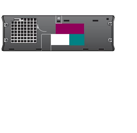
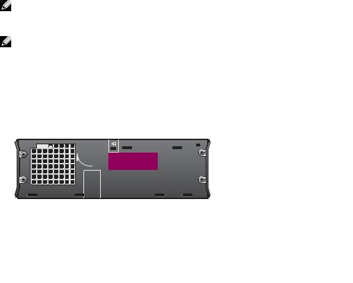
Back View
|
parallel |
link integrity light |
cover release knob |
connector |
network adapter |
|
|
 network activity light
line-out connector |
line-in connector |
vents (do not block)  diagnostic lights
power connector 
 USB connectors (5)
 serial connector
 video connector
Cable Cover and Power Adapter
Quick Reference Guide |
9 |

w w w . d e l l . c o m | s u p p o r t . d e l l . c o m
Setting Up Your Computer
NOTICE: When setting up your computer, secure all cables toward the back of your work area to prevent the cables from being pulled, tangled, or stepped on.
NOTICE: To prevent the computer from overheating and shutting down, do not place the computer in a poorly ventilated area.
NOTE: If you have ordered a computer without a hard drive, you can install a drive by using the drive rails that are included inside your computer (see "Installing a Hard Drive" on page 15).
Determining Placement and Orientation of the Computer
NOTICE: Do not place your monitor on top of the computer. Use a monitor stand.
NOTICE: Do not position your computer upside down.
10 Quick Reference Guide
NOTICE: In a high-vibration environment or when installing the computer under a surface or on a wall, use the optional wall-mount bracket. To order the bracket, contact Dell. For information on contacting Dell, see your online User’s Guide.
NOTE: To ensure proper ventilation, place the computer at least 5 cm (2 inches) from a vertical surface. Do not place the computer in an enclosed environment without ventilation.
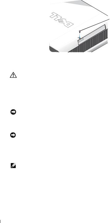
Installing a Device in the Module Bay
You can install a Dell™ portable device such as a floppy drive, CD/DVD drive, or second hard drive in the module bay. Your Dell computer ships with either a CD/DVD drive or an airbay (filler blank) installed in the module bay.
As a security feature, your computer is equipped with a module locking switch to secure a device in the module bay. To access the switch, remove the computer cover (see "Removing the Computer Cover" on page 16).
For added security, you may also secure a device in the module bay by using the device screw that ships with your computer (packaged separately).
module locking switch 
Quick Reference Guide |
11 |
w w w . d e l l . c o m | s u p p o r t . d e l l . c o m
 device screw
Connecting External Devices
CAUTION: Before performing any of the procedures in this section, follow the safety instructions in the Product Information Guide.
You must complete all steps to properly set up your computer. See the appropriate figures that follow the instructions.
1Use the USB connectors on the back of your computer to connect the keyboard and mouse.
2Connect the modem or network cable.
NOTICE: To connect a network cable, first plug the cable in to the network wall jack, and then in to the computer.
Insert the network cable, not the phone line, into the network connector. If you have an optional modem, connect the phone line to the modem.
NOTICE: Do not connect a modem cable to the network adapter. Voltage from telephone communications can cause damage to the network adapter.
3Connect the monitor.
Align and gently insert the monitor cable to avoid bending connector pins. Tighten the thumbscrews on the cable connectors.
NOTE: Some monitors have the video connector underneath the back of the screen. See the documentation that came with your monitor for its connector locations.
4 Connect the speakers.
12 Quick Reference Guide
5Connect power cables to the computer, monitor, and devices and insert the other ends of the power cables to electrical outlets.
6Press the power buttons to turn on the computer and monitor.
NOTE: Before you install any devices or software that did not ship with your computer, read the documentation that came with the software or device, or contact the vendor to verify that the software or device is compatible with your computer and operating system.
NOTE: Your computer may vary slightly from the following setup figures.
network connector
USB connector
|
|
|
|
|
|
|
|
|
|
|
|
|
|
|
|
|
|
|
|
|
|
|
|
|
13 |
|
|
|
|
|
|
|
|
|
|
|
|
|
|
|
|
|
|
|
|
|
|
|
|
|
|
|
|
|
|
|
|
|
|
|
|
|
|
|
|
|
|
|
|
|
|
|
|
|
|
|
|
|
|
|
|
|
|
|
|
|
|
|
|
|
|
|
|
|
|
|
|
|
|
|
|
|
|
|
|
|
|
|
|
|
|
|
|
|
|
|
|
|
|
|
|
|
|
|
|
|
|
|
|
|
|
|
|
|
|
|
|
|
|
|
|
|
|
|
|
|
|
|
|
|
|
|
|
|
|
|
|
|
|
|
|
|
|
|
|
|
|
|
|
|
|
|
|
|
|
|
|
|
|
|
|
|
|
|
|
|
|
|
|
|
|
|
|
|
|
|
|
|
|
|
|
|
|
|
|
|
|
|
|
|
|
|
|
|
|
|
|
|
|
|
|
|
|
|
|
|
|
|
|
|
|
|
|
|
|
|
|
|
|
|
|
|
|
|
|
|
|
|
|
|
|
Quick Reference Guide |
|
||||||
|
|
|
|
|
|
|
|
|
|
|
|
|
|
|
|
|
|
|
|||||||
|
|
|
|
|
|
|
|
|
|
|
|
|
|
|
|
|
|
|
|||||||
|
|
|
|
|
|
|
|
|
|
|
|
|
|
|
|
|
|
|
|||||||
|
|
|
|
|
|
|
|
|
|
||||||||||||||||

w w w . d e l l . c o m | s u p p o r t . d e l l . c o m
Connecting a DVI Monitor
If you have a DVI-compatible monitor, plug the cable from your monitor in to the white DVI display-connector on the computer back panel.
Connecting a VGA Monitor
If you have a VGA-compatible monitor, use the adapter cable to connect the cable from your monitor to the white DVI display-connector on the computer back panel.
14 Quick Reference Guide
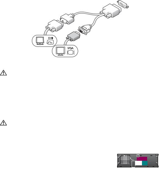
Connecting Two Monitors
Use the adapter cable to connect both a VGA monitor and a DVI monitor to the white DVI displayconnector on the computer back panel.
Installing a Hard Drive
CAUTION: Before you begin any of the procedures in this section, follow the safety instructions in the
Product Information Guide.
1If you are installing a new drive, attach the drive rails—located inside the cover—to the new drive.
2Attach the data and power cables to the hard drive connectors, being careful not to bend any of the pins.
3Slide the hard drive into the bracket.
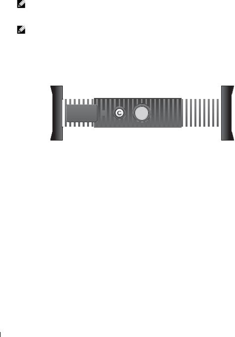
Connecting the AC Adapter
CAUTION: Before you begin any of the procedures in this section, follow the safety instructions in the
Product Information Guide.
1Connect the power adapter to the connector on the back of the computer. In order for the connection to be secure, verify that the latch engages completely. (An audible click will be heard or felt.)
2Connect a power cable to the
power adapter.
3 If your computer power-cable connector has a grounding wire, and you decide to connect it, continue with step 4. If you decide otherwise, go to step 5.
Quick Reference Guide |
15 |

w w w . d e l l . c o m | s u p p o r t . d e l l . c o m
CAUTION: If your power cord or adapter provides a green ground wire for connection to an electrical outlet, do not permit contact between the green ground wire and power leads because electrical shock, fire, or damage to your computer can occur (see the following figure).
4 Connect the metal ground connector to the grounding source on the outlet (see the following figure):
a Loosen the grounding source.
bSlide the metal ground connector behind the grounding source, and then tighten the grounding source.
5 Connect the AC power cable to the outlet.
|
grounding |
Attaching the Optional Cable Cover |
source |
|
1 Ensure that all external device cables are
threaded through the hole in the cable metal ground connector cover and connected to the computer back
panel.
2Hold the bottom of the cable cover and align the four tabs with the four slots on the computer back panel.
3 |
Insert the tabs into the slots and slide the |
cable cover |
|
cable cover toward the diagnostic lights (see |
(optional) |
|
the figure) until the cable cover is securely |
|
|
positioned. |
|
4 |
Install a security device in the security cable |
|
|
slot (optional). |
|
Inside Your Computer
|
security |
Removing the Computer Cover |
cable slot |
CAUTION: Before you begin any of the procedures in this section, follow the safety instructions in the Product Information Guide.
CAUTION: To avoid electrical shock, always unplug your computer from the power adapter before removing the cover.
16 Quick Reference Guide
CAUTION: To prevent static damage to components inside your computer, discharge static electricity from your body before you touch any of your computer’s electronic components. You can do so by touching an unpainted metal surface on the computer chassis.
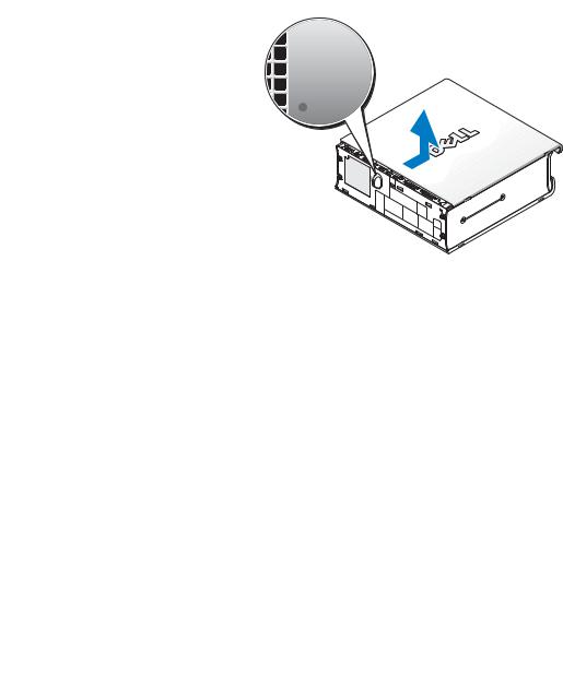
1Remove the computer cover.
a Rotate the cover release knob in a clockwise direction, as shown in the figure.
b Slide the computer cover forward 1 cm (0.5 inch), or until it stops, and then raise the cover.
Inside View
processor heat-sink fan shroud
chassis intrusion switch 
security cable slot 
 cover release knob
 speaker (optional)
 memory modules (2)
 hard drive
Quick Reference Guide |
17 |
w w w . d e l l . c o m | s u p p o r t . d e l l . c o m
Replacing the Computer Cover
CAUTION: Before you begin any of the procedures in this section, follow the safety instructions in the Product Information Guide.
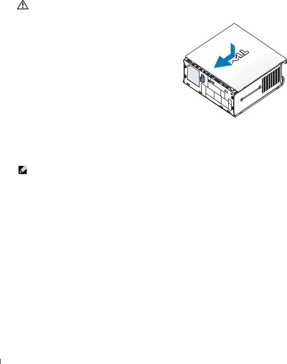
1 Replace the cover:
aLower and align the cover with the metal computer frame.
b Slide the cover until you hear or feel it click into place.
2 Connect your computer to its power adapter and connect devices to electrical outlets, and turn them on.
If the chassis intrusion detector is set to On, the following message appears on the screen after the next computer start-up:
ALERT! Cover was previously removed.
3Clear the chassis intrusion status by entering system setup and selecting Clear under the Intrusion Status option. For information on the chassis intrusion detector, see your online
User’s Guide.
NOTE: If an admin password has been assigned by someone else, contact your network administrator for information on resetting the chassis intrusion detector.
Solving Problems
Dell provides a number of tools to help you if your computer does not perform as expected. For the latest troubleshooting information available for your computer, see the Dell Support website at support.dell.com.
If computer problems occur that require help from Dell, write a detailed description of the error, beep codes, or diagnostics light patterns; record your Express Service Code and Service Tag below; and then contact Dell from the same location as your computer.
See "Finding Information" on page 5 for an example of the express service code and Service Tag.
Express Service Code:___________________________
Service Tag:___________________________
18 Quick Reference Guide

Dell Diagnostics
CAUTION: Before you begin any of the procedures in this section, follow the safety instructions located in the Product Information Guide.
When to Use the Dell Diagnostics
If you experience a problem with your computer, perform the checks in "Setting Up Your Computer" on page 10 and run the Dell Diagnostics before you contact Dell for technical assistance.
NOTICE: The Dell Diagnostics works only on Dell™ computers.
Enter system setup, review your computer’s configuration information, and ensure that the device you want to test is displayed in system setup and is active. For information on system setup, see your online User’s Guide.
Start the Dell Diagnostics from either your hard drive (see "Starting the Dell Diagnostics From Your Hard Drive" on page 19) or from the Drivers and Utilities CD (also known as the ResourceCD —see "Starting the Dell Diagnostics From the Drivers and Utilities CD" on page 19).
Starting the Dell Diagnostics From Your Hard Drive
1Turn on (or restart) your computer.
2When the DELL™ logo appears, press <F12> immediately.
NOTE: If you see a message stating that no diagnostics utility partition has been found, see "Starting the Dell Diagnostics From the Drivers and Utilities CD" on page 19.
If you wait too long and the operating system logo appears, continue to wait until you see the Microsoft® Windows® desktop. Then shut down your computer and try again. For information on shutting down your computer, see your online User’s Guide.
3When the boot device list appears, highlight Boot to Utility Partition and press <Enter>.
4When the Dell Diagnostics Main Menu appears, select the test you want to run (see page 20).
Starting the Dell Diagnostics From the Drivers and Utilities CD
1Insert the Drivers and Utilities CD.
2Shut down and restart the computer.
When the DELL logo appears, press <F12> immediately.
If you wait too long and the Windows logo appears, continue to wait until you see the Windows desktop. Then shut down your computer and try again.
NOTE: The next steps change the boot sequence for one time only. On the next start-up, the computer boots according to the devices specified in system setup.
Quick Reference Guide |
19 |

m |
3 |
When the boot device list appears, highlight Onboard or USB CD-ROM and press |
|
. c o |
|
<Enter>. |
|
d e l l |
4 |
Select Onboard or USB CD-ROM Device from the CD boot menu. |
|
o r t . |
5 |
Select the Boot from CD-ROM option from the menu that appears. |
|
p p |
6 |
Type 1 to start the ResourceCD menu. |
|
s u |
|||
7 Type 2 to start the Dell Diagnostics. |
|||
| |
|||
o m |
8 |
Select Run the 32 Bit Dell Diagnostics from the numbered list. If multiple versions are listed, |
|
l l . c |
|||
|
select the version appropriate for your computer. |
||
. d e |
9 |
When the Dell Diagnostics Main Menu appears, select the test you want to run (see |
|
w w |
|
page 20). |
|
w |
|
|
|
Dell Diagnostics Main Menu
1After the Dell Diagnostics loads and the Main Menu screen appears, click the button for the option you want.
Option |
Function |
|
|
Express Test |
Performs a quick test of devices. This test typically takes 10 to 20 minutes and |
|
requires no interaction on your part. Run Express Test first to increase the |
|
possibility of tracing the problem quickly. |
|
|
Extended Test |
Performs a thorough check of devices. This test typically takes 1 hour or more |
|
and requires you to answer questions periodically. |
|
|
Custom Test |
Tests a specific device. You can customize the tests you want to run. |
|
|
Symptom Tree |
Lists the most common symptoms encountered and allows you to select a test |
|
based on the symptom of the problem you are having. |
|
|
2 If a problem is encountered during a test, a message appears with an error code and a description of the problem. Write down the error code and problem description and follow the instructions on the screen.
If you cannot resolve the error condition, contact Dell.
NOTE: The Service Tag for your computer is located at the top of each test screen. If you contact Dell, technical support will ask for your Service Tag.
3 If you run a test from the Custom Test or Symptom Tree option, click the applicable tab described in the following table for more information.
Tab |
Function |
|
|
Results |
Displays the results of the test and any error conditions encountered. |
|
|
Errors |
Displays error conditions encountered, error codes, and the problem |
|
description. |
20 Quick Reference Guide
Tab |
Function |
|
|
Help |
Describes the test and may indicate requirements for running the test. |
|
|
Configuration |
Displays your hardware configuration for the selected device. |
|
The Dell Diagnostics obtains configuration information for all devices from |
|
system setup, memory, and various internal tests, and it displays the |
|
information in the device list in the left pane of the screen. The device list |
|
may not display the names of all the components installed on your computer |
|
or all devices attached to your computer. |
|
|
Parameters |
Allows you to customize the test by changing the test settings. |
|
|
4When the tests are completed, if you are running the Dell Diagnostics from the Drivers and Utilities CD, remove the CD.
5Close the test screen to return to the Main Menu screen. To exit the Dell Diagnostics and restart the computer, close the Main Menu screen.
Quick Reference Guide |
21 |

w w w . d e l l . c o m | s u p p o r t . d e l l . c o m
Power Supply Light
Light |
PSU State |
Description |
Troubleshooting |
State |
|
|
|
|
|
|
|
Off |
No AC, or a fault |
Indicates that the power supply is not receiving power |
Ensure that the electrical outlet is |
|
condition occurred |
from an electrical outlet, OR that the power supply |
working by testing it with another |
|
|
shut down due to a fault condition. |
device, such as a lamp. |
|
|
|
Verify that the AC power cable |
|
|
|
connection is properly seated in the |
|
|
|
power supply. If necessary, reseat the |
|
|
|
AC cable connection at the power |
|
|
|
supply. |
|
|
|
Disconnect the AC power cable |
|
|
|
from the power supply and the DC |
|
|
|
cable from the computer for at least |
|
|
|
10 seconds. Reattach the AC power |
|
|
|
cable to the power supply. The light |
|
|
|
on the power supply should turn |
|
|
|
yellow. Reattach the DC cable to the |
|
|
|
computer. The light on the power |
|
|
|
supply should turn green. |
|
|
|
|
Yellow |
AC present/no load |
Indicates that the power supply is attached to working |
Verify that the power supply is |
|
|
electrical outlet but not connected to the computer. |
completely plugged in to the |
|
|
|
computer and the retention latch is |
|
|
|
engaged. Reseat the connection if |
|
|
|
necessary. |
|
|
|
|
Green |
AC present/power to |
Indicates that the power supply is receiving power |
Check the power button light and |
|
load |
from the electrical outlet and is properly connected to |
see "System Lights" on page 22. |
|
|
the computer. |
|
System Lights
Your power button light and hard-drive light may indicate a computer problem.
Power Light |
Problem Description |
Suggested Resolution |
|
|
|
Solid green power |
An integrated system board device may |
Check "Diagnostic Lights" on page 23 to see if the |
light and no beep |
be faulty. |
specific problem is identified. If the problem is not |
code but the |
|
identified, contact Dell for technical assistance. |
computer locks up |
|
|
during POST |
|
|
22 Quick Reference Guide

Power Light |
Problem Description |
Suggested Resolution |
Solid green power light and no beep code and no video during POST
The monitor may be faulty or incorrectly installed.
Check "Diagnostic Lights" on page 23 to see if the specific problem is identified.
Solid green and a A problem was detected while the BIOS beep code during was executing.
POST
See "Running the Dell™ IDE Hard Drive Diagnostics" on page 27 for instructions on diagnosing the beep code. Also, check the diagnostic lights to see if the specific problem is identified.
Solid yellow |
The Dell Diagnostics is running a test, |
If the Dell Diagnostics is running, allow the testing |
|
or a device on the system board may be |
to complete. |
|
faulty or incorrectly installed. |
Check "Diagnostic Lights" on page 23 to see |
|
|
|
|
|
if the specific problem is identified. |
|
|
If the computer does not boot, contact Dell for |
|
|
technical assistance. |
|
|
|
Blinks green several |
A configuration error exists. |
Check "Diagnostic Lights" on page 23 to see |
times and then turns |
|
if the specific problem is identified. |
off |
|
|
|
|
|
Blinking green |
The computer is in the suspended state |
Press the power button to wake the computer. |
|
(Microsoft® Windows® 2000 and |
|
|
Windows XP). |
|
Solid green |
Power is on, and the computer is |
|
operating normally. |
No corrective action is required.
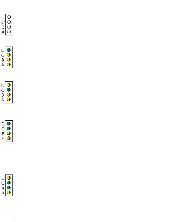
Diagnostic Lights
CAUTION: Before you begin any of the procedures in this section, follow the safety instructions located in the Product Information Guide.
To help you troubleshoot a problem, your computer has four lights labeled "A," "B," "C," and "D" on the back panel (see page 9). The lights can be yellow or green. When the computer starts normally, the patterns or codes on the lights change as the boot process completes. If the POST portion of system boot completes successfully, all four lights display solid green. If the computer malfunctions during the POST process, the pattern displayed on the lights may help identify where in the process the computer halted.
Quick Reference Guide |
23 |
w w w . d e l l . c o m | s u p p o r t . d e l l . c o m
Light |
Problem Description |
Suggested Resolution |
Pattern |
|
|
|
|
|
off |
The computer is in a normal off |
Plug the computer into a working electrical |
off |
condition or a possible pre-BIOS failure |
outlet and press the power button. |
off |
has occurred. |
|
off |
|
|
|
|
|
green |
A possible BIOS failure has occurred; the |
Run the BIOS Recovery utility, wait for recovery |
yellow |
computer is in the recovery mode. |
completion, and then restart the computer. |
yellow |
|
|
yellow |
|
|
|
|
|
yellow |
A possible processor failure has occurred. Reinstall the processor and restart the computer. |
|
green |
|
For information on reinstalling the processor, |
yellow |
|
see your online User’s Guide. |
yellow |
|
|
green |
Memory modules are detected, but a |
• If you have one memory module installed, |
green |
memory failure has occurred. |
reinstall it and restart the computer. For |
yellow |
|
information on reinstalling the memory |
yellow |
|
module, see your online User’s Guide. |
|
|
• If you have two memory modules installed, |
|
|
remove the modules, reinstall one module, |
|
|
and then restart the computer. If the computer |
|
|
starts normally, reinstall an additional module. |
|
|
• If available, install properly working memory |
|
|
of the same type into your computer. |
|
|
• If the problem persists, contact Dell. |
|
|
|
yellow |
A possible floppy or hard drive failure has |
Reseat all power and data cables and restart |
green |
occurred. |
the computer. |
green |
|
|
yellow |
|
|
24 Quick Reference Guide
Light |
Problem Description |
Suggested Resolution |
Pattern |
|
|
|
|
|
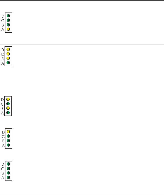
green |
A possible USB failure has occurred. |
Reinstall all USB devices, check cable |
green |
|
connections, and then restart the computer. |
green |
|
|
yellow |
|
|
yellow |
No memory modules are detected. |
• If you have one memory module installed, |
yellow |
|
reinstall it and restart the computer. For |
yellow |
|
information on reinstalling the memory |
green |
|
module, see your online User’s Guide. |
|
|
• If you have two memory modules installed, |
|
|
remove the modules, reinstall one module, |
|
|
and then restart the computer. If the computer |
|
|
starts normally, reinstall an additional module. |
|
|
• If available, install properly working memory |
|
|
of the same type into your computer. |
|
|
• If the problem persists, contact Dell. |
|
|
|
yellow |
Memory modules are detected, but a |
• Ensure that no special memory module/memory |
green |
memory configuration or compatibility |
connector placement requirements exist. For |
yellow |
error exists. |
information on memory modules, see your |
green |
|
online User’s Guide. |
|
|
• Verify that the memory modules that you are |
|
|
installing are compatible with your computer. |
|
|
• If the problem persists, contact Dell. |
|
|
|
yellow |
An error occurred prior to boot. |
• Ensure that the cables are properly connected |
green |
|
to the system board from the hard drive, CD |
green |
|
drive, and DVD drive. |
green |
|
• Check the computer message that appears |
|
|
on your monitor screen. |
|
|
• If the problem persists, contact Dell. |
|
|
|
green |
The computer is in a normal operating |
None. |
green |
condition after POST. |
|
green |
|
|
green |
|
|
Quick Reference Guide |
25 |

w w w . d e l l . c o m | s u p p o r t . d e l l . c o m
Beep Codes
Your computer might emit a series of beeps during start-up if the monitor cannot display errors or problems. This series of beeps, called a beep code, identifies a problem. One possible beep code (code 1-3-1) consists of one beep, a burst of three beeps, and then one beep. This beep code tells you that the computer encountered a memory problem.
If your computer beeps during start-up:
1Write down the beep code.
2See "Dell Diagnostics" on page 19 to identify a more serious cause.
3Contact Dell for technical assistance.
Code |
Cause |
Code |
Cause |
|
|
|
|
1-1-2 |
Microprocessor register failure |
3-3-4 |
Video Memory Test failure |
1-1-3 |
NVRAM read/write failure |
3-4-1 |
Screen initialization failure |
1-1-4 |
ROM BIOS checksum failure |
3-4-2 |
Screen retrace failure |
1-2-1 |
Programmable interval timer failure |
3-4-3 |
Search for video ROM failure |
1-2-2 |
DMA initialization failure |
4-2-1 |
No timer tick |
1-2-3 |
DMA page register read/write failure |
4-2-2 |
Shutdown failure |
1-3 |
Video Memory Test failure |
4-2-3 |
Gate A20 failure |
1-3-1 through |
Memory not being properly identified or used |
4-2-4 |
Unexpected interrupt in protected |
2-4-4 |
|
|
mode |
3-1-1 |
Slave DMA register failure |
4-3-1 |
Memory failure above address |
|
|
|
0FFFFh |
3-1-2 |
Master DMA register failure |
4-3-3 |
Timer-chip counter 2 failure |
3-1-3 |
Master interrupt mask register failure |
4-3-4 |
Time-of-day clock stopped |
3-1-4 |
Slave interrupt mask register failure |
4-4-1 |
Serial or parallel port test failure |
3-2-2 |
Interrupt vector loading failure |
4-4-2 |
Failure to decompress code to |
|
|
|
shadowed memory |
3-2-4 |
Keyboard Controller Test failure |
4-4-3 |
Math-coprocessor test failure |
3-3-1 |
NVRAM power loss |
4-4-4 |
Cache test failure |
3-3-2 |
Invalid NVRAM configuration |
|
|
|
|
|
|
26 Quick Reference Guide
Running the Dell™ IDE Hard Drive Diagnostics
The Dell IDE Hard Drive Diagnostics is a utility that tests the hard drive to troubleshoot or confirm a hard drive failure.
1Turn on your computer (if your computer is already on, restart it).
2When F2 = Setup appears in the upper-right corner of the screen, press <Ctrl><Alt><D>.
3Follow the instructions on the screen.
If a failure is reported, see "Hard Drive Problems" in your User’s Guide.
Resolving Software and Hardware Incompatibilities
If a device is either not detected during the operating system setup or is detected but incorrectly configured, you can use the Hardware Troubleshooter to resolve the incompatibility. In the Microsoft® Windows® 2000 operating system, you can also use Device Manager to resolve incompatibilities.
Windows XP
To resolve incompatibilities using the Hardware Troubleshooter:
1Click the Start button and click Help and Support.
2Type hardware troubleshooter in the Search field and click the arrow to start the search.
3Click Hardware Troubleshooter in the Search Results list.
4In the Hardware Troubleshooter list, click I need to resolve a hardware conflict on my computer, and click Next.
Windows 2000
To resolve incompatibilities using Device Manager:
1Click the Start button, point to Settings, and then click Control Panel.
2In the Control Panel window, double-click System.
3Click the Hardware tab.
4Click Device Manager.
5Click View and click Resources by connection.
6Double-click Interrupt request (IRQ).
Incorrectly configured devices are indicated by a yellow exclamation point (!) or a red X if the device has been disabled.
Quick Reference Guide |
27 |

w w w . d e l l . c o m | s u p p o r t . d e l l . c o m
7Double-click any device marked with an exclamation point to display the Properties window.
The Device status area in the Properties window reports the cards or devices that need to be reconfigured.
8Reconfigure the devices or remove the devices from the Device Manager. See the documentation that came with the device for information on configuring the device.
To resolve incompatibilities using the Hardware Troubleshooter:
1Click the Start button and click Help.
2Click Troubleshooting and Maintenance on the Contents tab, click Windows 2000 troubleshooters, and then click Hardware.
3In the Hardware Troubleshooter list, click I need to resolve a hardware conflict on my computer and click Next.
Using Microsoft® Windows® XP System Restore
The Microsoft® Windows® XP operating system provides System Restore to allow you to return your computer to an earlier operating state (without affecting data files) if changes to the hardware, software, or other system settings have left the computer in an undesirable operating state. See the Windows Help and Support Center for information on using System Restore.
NOTICE: Make regular backups of your data files. System Restore does not monitor your data files or recover them.
Creating a Restore Point
1Click the Start button and click Help and Support.
2Click System Restore.
3Follow the instructions on the screen.
Restoring the Computer to an Earlier Operating State
NOTICE: Before you restore the computer to an earlier operating state, save and close any open files and exit any open programs. Do not alter, open, or delete any files or programs until the system restoration is complete.
1Click the Start button, point to All Programs→ Accessories→ System Tools, and then click System Restore.
2Ensure that Restore my computer to an earlier time is selected and click Next.
3Click a calendar date to which you want to restore your computer.
The Select a Restore Point screen provides a calendar that allows you to see and select restore points. All calendar dates with available restore points appear in boldface type.
4Select a restore point and click Next.
If a calendar date has only one restore point, then that restore point is automatically selected. If two or more restore points are available, click the restore point that you prefer.
28 Quick Reference Guide

5Click Next.
The Restoration Complete screen appears after System Restore finishes collecting data and then the computer restarts.
6After the computer restarts, click OK.
To change the restore point, you can either repeat the steps using a different restore point, or you can undo the restoration.
Undoing the Last System Restore
NOTICE: Before you undo the last system restore, save and close all open files and exit any open programs. Do not alter, open, or delete any files or programs until the system restoration is complete.
1Click the Start button, point to All Programs→ Accessories→ System Tools, and then click System Restore.
2Click Undo my last restoration and click Next.
3Click Next.
The System Restore screen appears and the computer restarts.
4After the computer restarts, click OK.
Enabling System Restore
If you reinstall Windows XP with less than 200 MB of free hard-disk space available, System Restore is automatically disabled. To see if System Restore is enabled:
1Click the Start button and click Control Panel.
2Click System.
3Click the System Restore tab.
4Ensure that Turn off System Restore is unchecked.
Reinstalling Microsoft® Windows® XP
Before You Begin
If you are considering reinstalling the Windows XP operating system to correct a problem with a newly installed driver, first try using Windows XP Device Driver Rollback. (For information on Device Driver Rollback, see your online User’s Guide). If Device Driver Rollback does not resolve the problem, then use System Restore (see "Using Microsoft® Windows® XP System Restore" on page 28) to return your operating system to the operating state it was in before you installed the new device driver.
NOTICE: Before performing the installation, back up all data files on your primary hard drive. For conventional hard drive configurations, the primary hard drive is the first drive detected by the computer.
Quick Reference Guide |
29 |

w w w . d e l l . c o m | s u p p o r t . d e l l . c o m
To reinstall Windows XP, you need the following items:
•Dell™ Operating System CD
•Dell Drivers and Utilities CD
NOTE: The Drivers and Utilities CD contains drivers that were installed during assembly of the computer. Use the Drivers and Utilities CD to load any required drivers, including the drivers required if your computer has a RAID controller.
Reinstalling Windows XP
NOTICE: You must use Windows XP Service Pack 1 or later when you reinstall Windows XP.
To reinstall Windows XP, perform all the steps in the following sections in the order in which they are listed.
The reinstallation process can take 1 to 2 hours to complete. After you reinstall the operating system, you must also reinstall the device drivers, virus protection program, and other software.
NOTICE: The Operating System CD provides options for reinstalling Windows XP. The options can overwrite files and possibly affect programs installed on your hard drive. Therefore, do not reinstall Windows XP unless a Dell technical support representative instructs you to do so.
NOTICE: To prevent conflicts with Windows XP, disable any virus protection software installed on your computer before you reinstall Windows XP. See the documentation that came with the software for instructions.
Booting From the Operating System CD
1Save and close any open files and exit any open programs.
2Insert the Operating System CD. Click Exit if Install Windows XP message appears.
3Restart the computer.
4Press <F12> immediately after the DELL™ logo appears.
If the operating system logo appears, wait until you see the Windows desktop, and then shut down the computer and try again.
5Press the arrow keys to select CD-ROM, and press <Enter>.
6When the Press any key to boot from CD message appears, press any key.
Windows XP Setup
1When the Windows XP Setup screen appears, press <Enter> to select To set up Windows now.
2Read the information on the Microsoft Windows Licensing Agreement screen, and press <F8> to accept the license agreement.
3If your computer already has Windows XP installed and you want to recover your current Windows XP data, type r to select the repair option, and remove the CD.
30 Quick Reference Guide
Loading...