


 Loading...
Dell XPS 400 Service Manual
Dell™ XPS™ 400 Service Manual
About Your Computer |
Advanced Troubleshooting |
Before You Begin |
System Setup |
Removing the Computer Cover |
Removing and Installing Parts |
Technical Overview |
Replacing the Computer Cover |
Specifications |
|
|
|
Notes, Notices, and Cautions
NOTE: A NOTE indicates important information that helps you make better use of your computer.
NOTICE: A NOTICE indicates either potential damage to hardware or loss of data and tells you how to avoid the problem.
CAUTION: A CAUTION indicates a potential for property damage, personal injury, or death.
If you purchased a Dell™ n-Series computer, any references in this document to Microsoft® Windows® operating systems are not applicable.
Information in this document is subject to change without notice. © 2006 Dell Inc. All rights reserved.
Reproduction in any manner whatsoever without the written permission of Dell Inc. is strictly forbidden.
Trademarks used in this text: Dell, XPS, and the DELL logo are trademarks of Dell Inc.; Intel, Pentium, and SpeedStep are registered trademarks of Intel Corporation; Microsoft and Windows are registered trademarks of Microsoft Corporation.
Other trademarks and trade names may be used in this document to refer to either the entities claiming the marks and names or their products. Dell Inc. disclaims any proprietary interest in trademarks and trade names other than its own.
Model DCTA
August 2006 Rev. A01
file:///T|/htdocs/systems/xps400/sm/index.htm[8/3/2012 3:11:03 PM]
About Your Computer: Dell XPS 400 Service Manual
Back to Contents Page
About Your Computer
Dell™ XPS™ 400 Service Manual
 Front View of the Computer
 Back View of the Computer
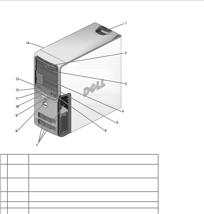
Front View of the Computer
1 |
cover latch |
Use this latch to remove the cover. See "Removing the Computer Cover." |
|
release |
|
2 |
CD or DVD |
The drive light is on when the computer reads data from the CD or DVD drive. |
|
activity |
|
|
light |
|
3 |
CD or DVD |
Press to eject a disc from the CD or DVD drive. |
|
eject |
|
|
button |
|
4 |
Floppy |
Can contain an optional floppy drive. |
|
drive bay |
|
5 |
FlexBay |
Can contain an optional floppy drive or optional Media Card Reader. |
6 |
IEEE 1394 |
Use the optional IEEE 1394 connector for high-speed data devices such as |
file:///T|/htdocs/systems/xps400/sm/about.htm[8/3/2012 3:11:06 PM]

About Your Computer: Dell XPS 400 Service Manual
|
connector |
digital video cameras and external storage devices. |
|
|
(optional) |
|
|
7 |
vents |
For adequate cooling, do not block any of the vents. |
|
|
|
NOTICE: Do not use the vents as handles; doing so may result in damage to |
|
|
|
your computer. Also, ensure that there is a minimum of two inches of space |
|
|
|
between all vents and any object near these vents. |
|
8 |
USB 2.0 |
Use the front USB connectors for devices that you connect occasionally, such |
|
|
connectors |
as joysticks or cameras. It is recommended that you use the back USB |
|
|
(2) |
connectors for devices that typically remain connected, such as printers, |
|
|
|
keyboards, and mice, or for bootable USB devices, which may not function |
|
|
|
properly if attached to the front connectors. |
|
9 |
power |
Press to turn on the computer. |
|
|
button |
|
|
|
|
NOTICE: To avoid losing data, do not use the power button to turn off the |
|
|
|
computer. Instead, perform an operating system shutdown. |
|
10 |
hard-drive |
The hard drive activity light is on when the computer reads data from or |
|
|
activity |
writes data to the hard drive. The light might also be on when a device such |
|
|
light |
as a CD player is operating. |
|
11 |
diagnostic |
Use the lights to help you troubleshoot a computer problem based on the |
|
|
lights (4) |
diagnostic code. For more information, see "Diagnostic Lights." |
|
12 |
headphone |
Use the headphone connector to attach headphones. |
|
|
connector |
|
|
13 |
microphone |
Use the microphone connector to attach a personal computer microphone for |
|
|
connector |
voice or musical input into a sound or telephony program. |
|
14 |
Service |
Used to identify your computer when you access the Dell Support website or |
|
|
Tag |
call technical support. |
|
|
|
|
|
Back View of the Computer
file:///T|/htdocs/systems/xps400/sm/about.htm[8/3/2012 3:11:06 PM]
About Your Computer: Dell XPS 400 Service Manual
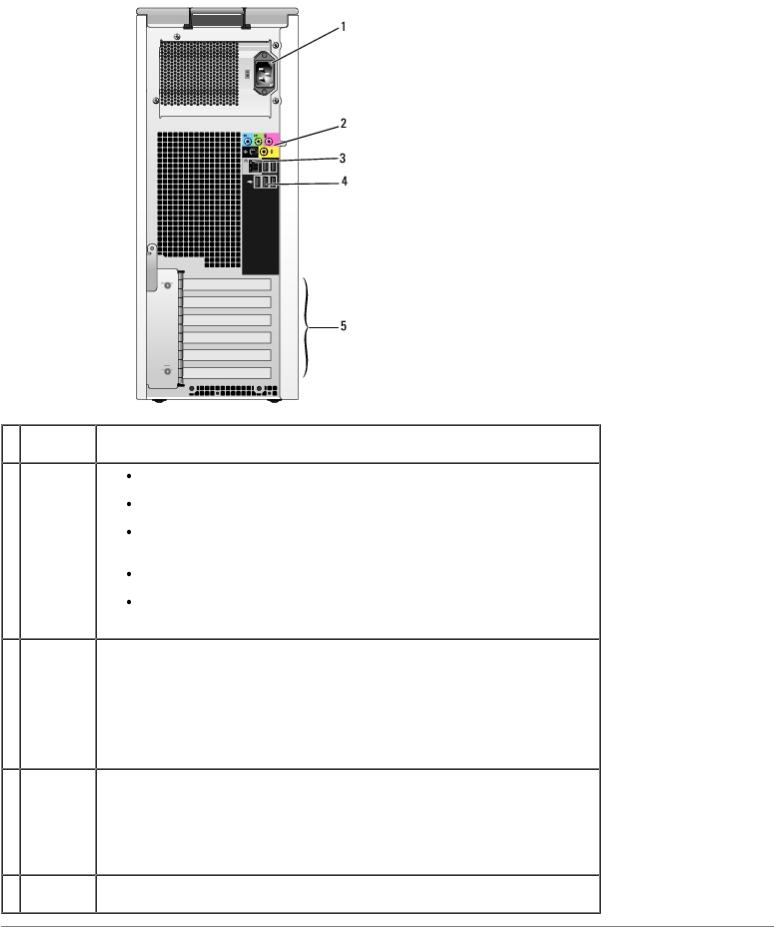
1 |
power |
Insert the power cable. |
|
connector |
|
2 |
sound |
Line-in connector — Use the blue line-in connector to attach a |
|
card |
record/playback device such as a cassette player, CD player, or VCR. |
|
connectors |
Line-out connector — Use the green line-out connector to attach |
|
(5) |
headphones and most speakers with integrated amplifiers. |
|
|
Microphone connector — Use the pink microphone connector to attach a |
|
|
personal computer microphone for voice or musical input into a sound or |
|
|
telephony program. |
|
|
Surround connector — Use the black surround connector to attach |
|
|
multichannel-capable speakers. |
|
|
Center/subwoofer (Center/LFE) connector — Use the yellow subwoofer |
|
|
connector to attach multiple speakers. |
3 |
network |
To attach your computer to a network or broadband device, connect one end of |
|
connector |
a network cable to either a network port or your network or broadband device. |
|
|
Connect the other end of the network cable to the network connector on your |
|
|
computer. A click indicates that the network cable has been securely attached. |
NOTE: Do not plug a telephone cable into the network connector.
On computers with a network connector card, use the connector on the card.
4USB 2.0 Use the back USB connectors for devices that typically remain connected, such connectors as printers, keyboards, and mice, or for bootable USB devices which may not
(5)function properly if attached to the front connectors (see "System Setup" for more information on booting to a USB device)
It is recommended that you use the front USB connectors for devices that you connect occasionally, such as joysticks or cameras.
5 card slots Access connectors for any installed PCI or PCI Express cards.
(6)
Back to Contents Page
file:///T|/htdocs/systems/xps400/sm/about.htm[8/3/2012 3:11:06 PM]
About Your Computer: Dell XPS 400 Service Manual
file:///T|/htdocs/systems/xps400/sm/about.htm[8/3/2012 3:11:06 PM]

Before You Begin: Dell XPS 400 Service Manual
Back to Contents Page
Before You Begin
Dell™ XPS™ 400 Service Manual
 Getting Started
 Recommended Tools
 Turning Off Your Computer
 Before Working Inside Your Computer
Getting Started
This chapter provides procedures for removing and installing the components in your computer. Unless otherwise noted, each procedure assumes that the following conditions exist:
 You have performed the steps in "Turning Off Your Computer" and "Before Working Inside Your Computer."
 You have read the safety information in your Dell™ Product Information Guide.
 A component can be replaced by performing the removal procedure in reverse order.
Recommended Tools
The procedures in this document may require the following tools:
 Small flat-blade screwdriver
 Phillips screwdriver
 Long Phillips screwdriver
 Flash BIOS update program floppy disk or CD
Turning Off Your Computer
NOTICE: To avoid losing data, save and close any open files and exit any open programs before you turn off your computer.
1.Shut down the operating system:
a.Save and close any open files, exit any open programs, click the Start button, and then click Turn Off Computer.
b.In the Turn off computer window, click Turn off.
The computer turns off after the operating system shutdown process finishes.
2.Ensure that the computer and any attached devices are turned off. If your computer and attached devices did not automatically turn off when you shut down your operating system, press and hold the power button for 4 seconds.
file:///T|/htdocs/systems/xps400/sm/before.htm[8/3/2012 3:11:07 PM]

Before You Begin: Dell XPS 400 Service Manual
Before Working Inside Your Computer
Use the following safety guidelines to help protect your computer from potential damage and to help ensure your own personal safety.
CAUTION: Before you begin any of the procedures in this section, follow the safety instructions in the Product Information Guide.
CAUTION: Handle components and cards with care. Do not touch the components or contacts on a card. Hold a card by its edges or by its metal mounting bracket. Hold a component such as a processor by its edges, not by its pins.
NOTICE: Only a certified service technician should perform repairs on your computer. Damage due to servicing that is not authorized by Dell is not covered by your warranty.
NOTICE: When you disconnect a cable, pull on its connector or on its strain-relief loop, not on the cable itself. Some cables have a connector with locking tabs; if you are disconnecting this type of cable, press in on the locking tabs before you disconnect the cable. As you pull connectors apart, keep them evenly aligned to avoid bending any connector pins. Also, before you connect a cable, ensure that both connectors are correctly oriented and aligned.
NOTICE: To avoid damaging the computer, perform the following steps before you begin working inside the computer.
1. Turn off your computer.
NOTICE: To disconnect a network cable, first unplug the cable from your computer and then unplug it from the network port or device.
2.Disconnect any telephone or telecommunication lines from the computer.
3.Disconnect your computer and all attached devices from their electrical outlets, and then press the power button to ground the system board.
NOTICE: Before touching anything inside your computer, ground yourself by touching an unpainted metal surface, such as the metal at the back of the computer. While you work, periodically touch an unpainted metal surface to dissipate any static electricity that could harm internal components.
Back to Contents Page
file:///T|/htdocs/systems/xps400/sm/before.htm[8/3/2012 3:11:07 PM]

Removing the Computer Cover: Dell XPS 400 Service Manual
Back to Contents Page
Removing the Computer Cover
Dell™ XPS™ 400 Service Manual
CAUTION: Before you begin any of the procedures in this section, follow the safety instructions in the Product Information Guide.
CAUTION: To guard against electrical shock, always unplug your computer from the electrical outlet before removing the cover.
NOTICE: Before touching anything inside your computer, ground yourself by touching an unpainted metal surface, such as the metal at the back of the computer. While you work, periodically touch an unpainted metal surface to dissipate any static electricity that could harm internal components.
1.Follow the procedures in "Before You Begin."
2.If you have installed a security cable, remove it from the security cable slot.
NOTICE: Ensure that sufficient space exists to support the removed cover—at least 30 cm (1 ft) of desk top space.
NOTICE: Ensure that you are working on a level, protected surface to avoid scratching either the computer or the surface on which it is resting.
3.Lay your computer on its side with the computer cover facing up.
4.Pull back the cover latch release on the top panel.
5. Locate the three hinge tabs on the bottom edge of the computer.
file:///T|/htdocs/systems/xps400/sm/cvrop.htm[8/3/2012 3:11:08 PM]

Removing the Computer Cover: Dell XPS 400 Service Manual
6.Grip the sides of the computer cover and pivot the cover up.
7.Lift the cover away and set it aside in a secure location.
Back to Contents Page
file:///T|/htdocs/systems/xps400/sm/cvrop.htm[8/3/2012 3:11:08 PM]
Technical Overview: Dell XPS 400 Service Manual
Back to Contents Page
Technical Overview
Dell™ XPS™ 400 Service Manual
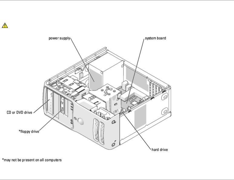
 Inside View of Your Computer
 System Board Components
 Power Supply DC Connector Pin Assignments
Inside View of Your Computer
CAUTION: Before you begin any of the procedures in this section, follow the safety instructions in the Product Information Guide.
System Board Components
file:///T|/htdocs/systems/xps400/sm/techov.htm[8/3/2012 3:11:13 PM]

Technical Overview: Dell XPS 400 Service Manual
Power Supply DC Connector Pin Assignments
file:///T|/htdocs/systems/xps400/sm/techov.htm[8/3/2012 3:11:13 PM]

Technical Overview: Dell XPS 400 Service Manual
DC Power Connector P1
Pin Number |
Signal Name |
Color |
Wire Gauge |
1 |
+3.3 VDC |
Orange |
18-AWG |
2 |
+3.3 VDC |
Orange |
18-AWG |
3 |
COM |
Black |
18-AWG |
4 |
+5 VDC |
Red |
18-AWG |
5 |
COM |
Black |
18-AWG |
6 |
+5 VDC |
Red |
18-AWG |
7 |
COM |
Black |
18-AWG |
8 |
POK |
Gray |
18-AWG |
9 |
+5 VFP |
Purple |
18-AWG |
file:///T|/htdocs/systems/xps400/sm/techov.htm[8/3/2012 3:11:13 PM]

Technical Overview: Dell XPS 400 Service Manual
10 |
+12 VB DC |
White |
18-AWG |
11 |
+12VB DC |
White |
18-AWG |
12 |
+3.3 VDC |
Orange |
18-AWG |
13 |
+3.3 VDC |
Orange |
18-AWG |
14 |
-12 VDC |
Blue |
18-AWG |
15 |
COM |
Black |
18-AWG |
16 |
PS-ON |
Green |
18-AWG |
17 |
COM |
Black |
18-AWG |
18 |
COM |
Black |
18-AWG |
19 |
COM |
Black |
18-AWG |
20 |
N/C |
N/C |
18-AWG |
21 |
+5 VDC |
Red |
18-AWG |
22 |
+5 VDC |
Red |
18-AWG |
23 |
+5 VDC |
Red |
18-AWG |
24 |
COM |
Black |
18-AWG |
DC Power Connector P2
 Pin Number
  Signal Name
  18-AWG Wire
1 |
COM |
Black |
2 |
COM |
Black |
3 |
+12 VA DC |
Yellow |
4 |
+12 VA DC |
Yellow |
DC Power Connect P3 and P5
 Pin Number
  Signal Name
  18-AWG Wire
1 |
+3.3 VDC |
Orange |
2 |
COM |
Black |
3 |
+5 VDC |
Red |
file:///T|/htdocs/systems/xps400/sm/techov.htm[8/3/2012 3:11:13 PM]

Technical Overview: Dell XPS 400 Service Manual
4 |
COM |
Black |
5 |
+12 VB DC |
White |
DC Power Connector P4
 Pin Number
  Signal Name
  18-AWG Wire
1 |
N/C |
N/C |
2 |
COM |
Black |
3 |
COM |
Black |
4 |
+3.3 VDC |
Orange |
5 |
+5 VDC |
Red |
6 |
+12A VDC |
Yellow |
DC Power Connector P7
 Pin Number
  Signal Name
  18-AWG Wire
1 |
+5 VDC |
Red |
2 |
COM |
Black |
3 |
COM |
Black |
4 |
+12 A VDC |
Yellow |
DC Power Connectors P8, P9, and P10
 Pin Number
  Signal Name
  18-AWG Wire
1 |
+12 VA DC Yellow |
file:///T|/htdocs/systems/xps400/sm/techov.htm[8/3/2012 3:11:13 PM]

Technical Overview: Dell XPS 400 Service Manual
2 |
COM |
Black |
3 |
COM |
Black |
4 |
+5V DC |
Red |
NOTE: The P10 connector is intended for use with PCI Express graphics cards that have power requirements exceeding 75 watts.
DC Power Connector P11
 Pin Number
  Signal Name
  18-AWG Wire
1 |
+12 VB DC |
White |
2 |
COM |
Black |
3 |
COM |
Black |
4 |
+5V DC |
Red |
DC Power Connector P12
 Pin Number
  Signal Name
  18-AWG Wire
1 |
+12 B VDC |
White |
2 |
+12 B VDC |
White |
3 |
+12 B VDC |
White |
4 |
COM |
Black |
5 |
COM |
Black |
6 |
COM |
Black |
Back to Contents Page
file:///T|/htdocs/systems/xps400/sm/techov.htm[8/3/2012 3:11:13 PM]

Specifications: Dell Dimension 9150 Service Manual
Back to Contents Page
Specifications
Dell™ XPS™ 400 Service Manual
Processor |
|
Processor type |
Intel® Pentium® 4 Socket-T with Hyper- |
|
Threading or Dual-Core support |
Cache |
2 MB |
Memory |
|
Type |
dual-channel 533and 667-MHz DDR2 |
Memory connectors |
four |
Memory capacities |
256 MB, 512 MB, or 1 GB |
Minimum memory |
512 MB |
Maximum memory |
4 GB |
BIOS address |
F0000h |
Computer Information |
|
Chipset |
Intel 945P |
DMA channels |
eight |
Interrupt levels |
24 |
BIOS chip (NVRAM) |
4 Mb |
NIC |
integrated-network interface capable of |
|
10/100/1000-Mbps communication |
System clock |
800or 1066-MHz data rate |
Video |
|
Type |
PCI Express |
Audio |
|
Type |
internal 7.1 channel or PCI option cards |
Expansion Bus |
|
Bus type |
PCI 32 bit |
|
PCI Express x1, x4, and x16 |
Bus speed |
PCI 33 MHz |
|
PCI Express 100 MHz |
Bus throughput |
PCI Express: |
|
x1 slot bidirectional speed — 500 |
|
MB/s |
file:///T|/htdocs/systems/xps400/sm/specs.htm[8/3/2012 3:11:15 PM]
Specifications: Dell Dimension 9150 Service Manual |
|
|
|
|
x4 slot bidirectional speed — 2 |
|
|
|
|
|
GB/s |
|
|
x16 slot bidirectional speed — 8 |
|
|
GB/s |
|
PCI |
|
|
connectors |
three |
|
connector size |
120 pins |
|
connector data width (maximum) |
32 bits |
|
PCI Express |
|
|
connector |
one x1 |
|
connector size |
36 pins |
|
connector data width (maximum) |
1 PCI Express lane |
|
PCI Express |
|
|
connector |
one x4 |
|
connector size |
98 pins |
|
connector data width (maximum) |
4 PCI Express lanes |
|
PCI Express |
|
|
connector |
one x16 |
|
connector size |
164 pins |
|
connector data width (maximum) |
16 PCI Express lanes |
|
Drives |
|
|
Externally accessible: |
|
|
|
two 3.5-inch drive bays (FlexBay) |
|
|
two 5.25-inch drive bays |
|
Available devices |
serial ATA drives (2), floppy drive, USB |
|
|
memory devices, CD drive, CD-RW drive, |
|
|
DVD drive, DVD-RW drive, Media Card |
|
|
Reader, and DVD/CD-RW combo drive |
|
Internally accessible: |
two 3.5-inch hard-drive bays |
|
Connectors |
|
|
|
|
|
External connectors: |
|
|
IEEE 1394 |
one front-panel 6-pin serial connector |
|
|
(with optional card) |
|
Video |
15-pin VGA connector |
|
|
28-pin DVI connector |
|
Network adapter |
RJ-45 connector |
|
USB |
two front-panel and five back-panel USB |
|
|
2.0-compliant connectors |
|
Audio |
five back-panel connectors for line-in, |
|
|
line-out, microphone, surround, and |
|
|
center/Low Frequency Effects (LFE) |
file:///T|/htdocs/systems/xps400/sm/specs.htm[8/3/2012 3:11:15 PM]

Specifications: Dell Dimension 9150 Service Manual |
|
|
|
|
channel; two front-panel connectors for |
|
|
|
|
|
headphones/microphone |
System board connectors: |
|
|
|
|
|
Primary IDE drive |
|
40-pin connector |
Serial ATA |
|
four 7-pin connectors |
FlexBay Drive |
|
USB 10-pin header for optional floppy |
|
|
drive or optional Media Card Reader (3.5- |
|
|
inch bay devices) |
Fan |
|
two 3-pin and one 5-pin connector |
PCI |
|
three 120-pin connectors |
PCI Express x1 |
|
36-pin connector |
PCI Express x4 |
|
98-pin connector |
PCI Express x16 |
|
164-pin connector |
 Controls and Lights
Power control
Power light
 Hard-drive access light
Link integrity light (on integrated network adapter)
Activity light (on integrated network adapter)
 Diagnostic lights Standby power light
 push button
green light — Blinking green in sleep state; solid green for power-on state.
amber light — Blinking amber indicates a problem with the power supply inside the computer. If the system cannot boot and there is a solid amber light, this indicates a problem with the system board (see "Power Lights").
 green
green
green light — A good connection exists between a 10-Mbps network and the computer.
orange light — A good connection exists between a 100-Mbps network and the computer.
off (no light) — The computer is not detecting a physical connection to the network.
yellow light — Blinking indicates activity on the network.
four lights on the front panel (see "Diagnostic Lights")
 AUXPWR on the system board
Power |
|
DC power supply: |
|
Wattage |
375 W |
Heat dissipation |
1280 BTU/hr |
NOTE: Heat dissapation is calculated based upon the power supply wattage rating.
Voltage (See the safety instructions  manual selection power supplies — 90 to
file:///T|/htdocs/systems/xps400/sm/specs.htm[8/3/2012 3:11:15 PM]

Specifications: Dell Dimension 9150 Service Manual |
|
|
|
|
|
|
in the Product Information Guide |
|
135 V and 180 to 265 V at 50/60 Hz |
|
|
|
|
||||
|
for important voltage setting |
|
|
|
|
|
information.) |
|
|
|
|
|
Backup battery |
|
3-V CR2032 lithium coin cell |
||
|
Physical |
|
|
|
|
|
Height |
|
46.48 cm (18.3 inches) |
||
|
Width |
|
18.54 cm (7.3 inches) |
||
|
Depth |
|
45.42 cm (17.88 inches) |
||
|
Weight |
|
15.4 kg (34 lb) |
||
|
Environmental |
|
|
|
|
|
Temperature: |
|
|
|
|
|
Operating |
|
10° to 35°C (50° to 95°F) |
||
|
Storage |
|
–40° to 65°C (–40° to 149°F) |
||
|
Relative humidity |
|
20% to 80% (noncondensing) |
||
|
Maximum vibration: |
|
|
|
|
|
Operating |
|
0.25 G at 3 to 200 Hz at 0.5 octave/min |
||
|
Storage |
|
0.5 G at 3 to 200 Hz at 1 octave/min |
||
|
Maximum shock: |
|
|
|
|
|
Operating |
|
bottom half-sine pulse with a change in |
||
|
|
|
velocity of 20 inches/sec (50.8 cm/sec) |
||
|
Storage |
|
27-G faired square wave with a velocity |
||
|
|
|
change of 200 inches/sec (508 cm/sec) |
||
|
Altitude: |
|
|
|
|
|
Operating |
|
–15.2 to 3048 m (–50 to 10,000 ft) |
||
|
Storage |
|
–15.2 to 10,668 m (–50 to 35,000 ft) |
||
|
|
|
|
|
|
|
Back to Contents Page |
|
|
|
|
file:///T|/htdocs/systems/xps400/sm/specs.htm[8/3/2012 3:11:15 PM]

Advanced Troubleshooting: Dell XPS 400 Service Manual
Back to Contents Page
Advanced Troubleshooting
Dell™ XPS™ 400 Service Manual
 Power Lights
 Diagnostic Lights
 Beep Codes
Power Lights
CAUTION: Before you begin any of the procedures in this section, follow the safety instructions in the Product Information Guide.
The power button light located on the front of the computer illuminates and blinks or remains solid to indicate different states:
 If the power light is green and the computer is not responding.
 Ensure the display is connected and powered on.
 If the display is connected and powered on, see "Diagnostic Lights".
 If the power light is blinking green, the computer is in standby mode. Press a key on the keyboard, move the mouse, or press the power button to resume normal operation.
 If the power light is off, the computer is either turned off or is not receiving power.
 Reseat the power cable into both the power connector on the back of the computer and the electrical outlet.
 If the computer is plugged into a power strip, ensure that the power strip is plugged into an electrical outlet and that the power strip is turned on. Also bypass power protection devices, power strips, and power extension cables to verify that the computer turns on properly.
 Ensure that the electrical outlet is working by testing it with another device, such as a lamp.
 Ensure that the main power cable and front panel cable are securely connected to the system board.
 If the power light is blinking amber, the computer is receiving electrical power, but an internal power problem might exist.
 Ensure that the voltage selection switch is set to match the AC power at your location (if applicable).
 If the power light is steady amber, a device might be malfunctioning or incorrectly installed.
 Remove and then reinstall the memory modules.
 Remove and then reinstall any cards.
 Remove and then reinstall the graphics card, if applicable.
 Ensure that all power cables are securely connected to the system board.
Diagnostic Lights
CAUTION: Before you begin any of the procedures in this section, follow the safety instructions in the Product Information Guide.
file:///T|/htdocs/systems/xps400/sm/adtshoot.htm[8/3/2012 3:11:19 PM]
Advanced Troubleshooting: Dell XPS 400 Service Manual
To help you troubleshoot a problem, your computer has four lights labeled "1," "2," "3," and "4" on the front panel (see
"Front View of the Computer"). When the computer starts normally, the lights flash. After the computer starts, all four lights display solid green. If the computer malfunctions, the color and sequence of the lights identify the problem.
Light Pattern |
Problem Description |
The computer is in a normal "off" condition or a possible pre-BIOS failure has occurred.
The diagnostic lights are not lit after the system successfully boots to the operating system.
A possible processor failure has occurred.
Memory modules are detected, but a memory failure has occurred.
Suggested Resolution
Plug the computer into a working electrical outlet. Also see "Power Lights."
Reinstall the processor and restart the computer.
 If you have two or more memory modules installed, remove the modules, reinstall one module (see "Memory"), and then restart the computer. If the computer starts normally, reinstall an additional module. Continue until you have identified a faulty module or reinstalled all modules without error.
 If available, install properly working memory of the same type into your computer (see "Memory").
 If the problem persists, contact Dell.
A possible graphics |
If the computer has a graphics card, remove the card (see "Cards"), |
card failure has |
reinstall it, and then restart the computer. |
occurred. |
If the problem still exists, install a graphics card that you know works |
|
and restart the computer. |
|
If the problem persists, contact Dell. |
A possible floppy drive or hard drive failure has occurred.
A possible USB failure has occurred.
No memory modules are detected.
Reseat all power and data cables and restart the computer.
Reinstall all USB devices, check cable connections, and then restart the computer.
 If you have two or more memory modules installed, remove the modules, reinstall one module (see "Memory"), and then restart the computer. If the computer starts normally, reinstall an additional module. Continue until you have identified a faulty module or reinstalled all modules without error.
 If available, install properly working memory of the same type into your computer (see "Memory").
 If the problem persists, contact Dell.
Memory modules are |
|
Ensure that no special memory module/memory connector placement |
detected, but a |
|
requirements exist (see "Memory"). |
memory configuration |
|
Verify that the memory modules that you are installing are compatible |
or compatibility error |
|
with your computer (see "Memory"). |
exists. |
|
If the problem persists, contact Dell. |
A possible expansion |
1. |
Determine if a conflict exists by removing a card (not a graphics card) |
card failure has |
|
and restarting the computer (see "Cards"). |
occurred. |
2. |
If the problem persists, reinstall the card that you removed, remove a |
|
|
different card, and then restart the computer. |
|
3. Repeat this process for each card. If the computer starts normally, |
|
|
|
troubleshoot the last card removed from the computer for resource |
|
|
conflicts (see "Cards"). |
|
4. |
If the problem persists, contact Dell. |
file:///T|/htdocs/systems/xps400/sm/adtshoot.htm[8/3/2012 3:11:19 PM]
Loading...