


Dell™ OptiPlex™ GX300 System User's Guide
Introduction
Setup and Operation
System Setup
Installing Upgrades
Troubleshooting
Specifications
NOTE: You can obtain the latest version of this document from the Dell support Web site at http://support.dell.com.
Model MMP
Notes, Notices, and Cautions
Throughout this guide, there may be blocks of text printed in bold type or in italic type. These blocks are notes, notices, and cautions, and they are used as follows:
NOTE: A NOTE indicates important information that helps you make better use of your system.
NOTICE: A NOTICE indicates either potential damage to hardware or loss of data and tells you how to avoid the problem.
CAUTION: A CAUTION indicates a potentially hazardous situation which, if not avoided, may result in minor or moderate injury.
Information in this document is subject to change without notice. © 2000-2003 Dell Computer Corporation. All rights reserved.
Reproduction in any manner whatsoever without the written permission of Dell Computer Corporation is strictly forbidden.
Trademarks used in this text: Dell, OptiPlex, OptiFrame, Dell OpenManage, Dimension, Latitude, Inspiron, and DellWare are trademarks of Dell Computer Corporation;
Microsoft, Windows, MS-DOS, and Windows NT are registered trademarks of Microsoft Corporation; Intel and Pentium are registered trademarks of Intel Corporation; 3Com is a registered trademark of 3Com Corporation; IBM and OS/2 are registered trademarks of International Business Machines Corporation; Novell and NetWare are registered trademarks of Novell, Inc. As an ENERGY STAR Partner, Dell Computer Corporation has determined that this product meets the ENERGY STAR guidelines for energy efficiency.
Other trademarks and trade names may be used in this document to refer to either the entities claiming the marks and names or their products. Dell Computer Corporation disclaims any proprietary interest in trademarks and trade names other than its own.
Initial release: 8 Aug 1999
Last revised: 31 Jan 2003

Back to Contents Page
Basic Checks: Dell™ OptiPlex™ GX300 System User's Guide
Overview |
Checking Connections and Switches |
Backing Up Your Files |
Look and Listen |
Basic Checks |
System Setup |
|
|
Overview
If your Dell computer system is not working as expected, and if you are not sure what to do, start your troubleshooting with the procedures in this section. This section guides you through basic steps to solve basic computer problems. It also directs you to further detailed troubleshooting information and procedures to solve more complex problems.
Backing Up Your Files
If your system is behaving erratically, back up your files immediately. If your system has a tape drive installed, see the documentation that came with the tape backup software for instructions on performing a backup operation. Otherwise, see your operating system documentation for information on backing up data files.
Basic Checks
See the following sections in the order indicated until the problem is resolved:
•If your computer is wet or damaged, see "Troubleshooting a Wet Computer" or "Troubleshooting a Damaged Computer."
•Perform the steps in "Checking Connections and Switches."
•Perform the steps in "Look and Listen."
•If your system did not complete the boot (start-up) routine, see "Getting Help."
NOTE: The boot routine is the operating system's attempt to load its files into memory from the boot-up sector on the hard-disk drive or another bootable device.
•If your system displayed a message or emitted a beep code, see "Messages and Codes."
•Verify the settings in System Setup.
•Run the Dell Diagnostics.
Checking Connections and Switches
Improperly set switches and controls and loose or improperly connected cables are the most likely source of problems for your computer, monitor, or other peripheral (such as a printer, keyboard, mouse, or other external equipment).
NOTE: See "Controls and Indicators" and "Connecting Peripheral Devices" for the location of your computer's external connections and switches.
Complete the following steps in the order indicated to check all the connections and switches:
1.Turn off the system, including any attached peripherals (such as the monitor, keyboard, printer, external drives, scanners, or plotters). Disconnect all the AC power cables from their electrical outlets.
2.If your computer is connected to a power strip, turn the power strip off and then on again. If the problem is not resolved, try another power strip or connect the system directly to an electrical outlet to see if the original power strip is faulty.
3.Connect the system to a different electrical outlet.
If doing so corrects the problem, the original outlet is faulty.
4.Reconnect the system to an electrical outlet. Make sure that all connections fit tightly together, and turn on the system.
5.If the problem is resolved, you have corrected a faulty connection.
6.If your monitor is not operating properly, see "Troubleshooting the Monitor."
7.If your keyboard is not operating properly, see "Troubleshooting the Keyboard."
8.If your mouse or printer is not operating properly, see "Troubleshooting I/O Ports." Otherwise, see "Look and Listen."
Look and Listen
Looking at and listening to your system is important in determining the source of a problem. Look and listen for the indications described in Table 1.
If after looking and listening to your computer you have not resolved the problem, continue with the recommendations in "System Setup."
Table 1. Boot Routine Indications
Look/Listen for:
An error message
The monitor's power indicator
The power and hard-disk drive indicators
The keyboard indicators

 Action

 See "Messages and Codes."
Most monitors have a power indicator (usually on the front bezel). If the monitor's power indicator does not light up, see "Troubleshooting the Monitor."
Use the power and hard-disk drive indicators to help you identify a system problem when you press the power button to turn on the computer but the system does not boot.
Most keyboards have one or more indicators (usually in the upper-right corner). Press <Num Lock>, <Caps Lock>, and <Scroll Lock> to toggle the keyboard indicators on and off. If the keyboard indicators do not light up, see "Troubleshooting the Keyboard."
The diskette-drive access indicator
The diskette-drive access indicator should quickly flash on and off when you access data on the diskette drive. On a system running a Microsoft® Windows® operating system, you can test the drive by opening Windows Explorer and clicking the icon for drive A. If the diskette-drive access indicator does not light up, see "Troubleshooting Drives."
The hard-disk drive access indicator
The hard-disk drive access indicator should quickly flash on and off when you access data on the hard-disk drive. On a system running a Windows operating system, you can test the drive by opening Windows Explorer and clicking the icon for drive C. If the hard-disk drive access indicator does not light up, see "Troubleshooting Drives."
A series of beeps |
See "Messages and Codes." |
An unfamiliar constant scraping or grinding sound when you access a drive
The absence of a familiar sound
Make sure the sound is not caused by the application program you are running. The sound could be caused by a hardware malfunction. See "Getting Help" for instructions on getting technical assistance from Dell.
When you turn on your system, you can hear the hard-disk drive spin up, and the system tries to access the boot files from the hard-disk drive or the diskette drive. If your system boots, see "Dell Diagnostics." If your system does not boot, see "Getting Help."
System Setup
You can easily correct certain system problems by verifying the correct settings in System Setup. When you boot your system, your system checks the system configuration information and compares it with the current hardware configuration. If your system hardware configuration does not match the information recorded by System Setup, an error message may appear on your screen.
This problem can happen if you changed your system's hardware configuration and forgot to run System Setup. To correct this problem, enter System Setup, correct the setting for the corresponding System Setup program option, and reboot your system.
If after checking the settings in System Setup you have not resolved the problem, see "Dell Diagnostics."
Back to Contents Page

Back to Contents Page
Battery: Dell™ OptiPlex™ GX300 System User's Guide
Overview
Replacing the Battery
Overview
A 3.0-volt (V) CR2032 coin-cell battery installed on the system board maintains system configuration, date, and time information in a special section of memory.
The operating life of the battery can extend up to ten years. The battery may need replacing if an incorrect time or date is displayed during the boot routine along with a message such as:
Time-of-day not set - please run SETUP program
or
Invalid configuration information - please run SETUP program
or
Strike the F1 key to continue,
F2 to run the setup utility
To determine whether you need to replace the battery, reenter the time and date through System Setup and exit the program properly to save the information. Turn off your system and disconnect it from the electrical outlet for a few hours; then reconnect and turn on your system. Enter System Setup. If the date and time are not correct in System Setup, replace your battery.
You can operate your system without a battery; however, without a battery, the system configuration information is erased if the system is turned off or unplugged from the electrical outlet. In this case, you must enter System Setup and reset the configuration options.
CAUTION: There is a danger of the new battery exploding if it is incorrectly installed. Replace the battery only with the same or equivalent type recommended by the manufacturer. Discard used batteries according to the manufacturer's instructions.
NOTE: Before disconnecting a peripheral from the system or removing a component from the system board, verify that the standby power light-emitting diode (LED) on the system board has turned off. For the location of this LED, see Figure 3 in "Inside Your Computer."
Replacing the Battery
To replace the system battery, perform the following steps.
CAUTION: Before you remove the computer cover, see "Safety First — For You and Your Computer."
1.If you have not already done so, make a copy of your system configuration information in System Setup.
If the settings are lost while you are replacing the battery, refer to your written or printed copy of the system configuration information to restore the correct settings.
2.Remove the computer cover according to the instructions in "Removing and Replacing the Computer Cover."
3.Remove the accelerated graphics port (AGP) card brace according to the instructions in "Removing and Replacing the AGP Card Brace."
4.Remove the battery.
See Figure 3 in "Inside Your Computer" for the location of the battery.
NOTICE: If you pry the battery out of its socket with a blunt object, be careful not to touch the system board with the object. Make certain that the object is inserted between the battery and the socket before you attempt to pry out the battery. Otherwise, you may damage the system board by prying off the socket or by breaking circuit traces on the system board.
Pry the battery out of its socket with your fingers or with a blunt, nonconductive object, such as a plastic screwdriver.
5.Install the new battery.
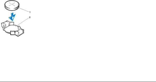
Orient the battery with the side labeled "+" facing up (see Figure 1). Then insert the battery into the socket, and snap it into place.
Figure 1. Replacing the System Battery
1Battery
2Battery socket
6.Replace the AGP card brace.
7.Replace the computer cover, reconnect your computer and peripherals to their electrical outlets, and turn them on.
8.Enter System Setup, and confirm that the battery is operating properly.
Enter the correct time and date through System Setup's System Time and System Date options. Also, use the copy you made in step 1 of the system configuration information to restore the correct settings for other System Setup options. Then exit System Setup.
9.Turn off and unplug your computer. Leave the computer turned off for at least 10 minutes.
10.After 10 minutes, plug in the computer, turn it on, and enter System Setup. If the time and date are still incorrect, see "Getting Help" for instructions on obtaining technical assistance.
Back to Contents Page
Back to Contents Page
Contacting Dell: Dell™ OptiPlex™ GX300 System User's Guide
Overview |
Europe Contact Numbers |
International Dialing Codes |
Asia and Other Regions Contact Numbers |
Americas Contact Numbers |
|
|
|
Overview
When you need to contact Dell, use the telephone numbers, codes, and electronic addresses provided in the following sections. "International Dialing Codes" provides the various codes required to make long-distance and international calls. "Americas Contact Numbers," "Europe Contact Numbers," and "Asia and Other Regions Contact Numbers" provide local telephone numbers, area codes, toll-free numbers, and e-mail addresses, if applicable, for each department or service available in various countries around the world.
If you are making a direct-dialed call to a location outside of your local telephone service area, determine which codes to use (if any) in "International Dialing Codes," in addition to the local numbers provided in the other sections.
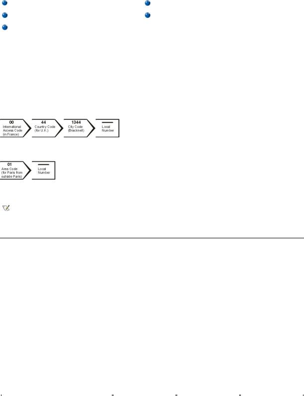
For example, to place an international call from Paris, France to Bracknell, England, dial the international access code for France followed by the country code for the U.K., the city code for Bracknell, and then the local number as shown in the following illustration:
To place a long-distance call within your own country, use area codes instead of international access codes, country codes, and city codes. For example, to call Paris, France from Montpellier, France, dial the area code plus the local number as shown in the following illustration:
The codes required depend on where you are calling from as well as the destination of your call; in addition, each country has a different dialing protocol. If you need assistance in determining which codes to use, contact a local or an international operator.
NOTES: Toll-free numbers are for use only within the country for which they are listed. Area codes are most often used to call long distance within your own country (not internationally)—in other words, when your call originates in the same country you are calling.
Have your Express Service Code ready when you call. The code helps Dell's automated-support telephone system direct your call more efficiently.
International Dialing Codes
Click a listed country to obtain the appropriate contact numbers.
|
International Access |
|
|
Country (City) |
Code |
Country Code |
City Code |
|
|
|
|
|
|
|
|
Australia (Sydney) |
0011 |
61 |
2 |
|
|
|
|
|
|
|
|
Austria (Vienna) |
900 |
43 |
1 |
|
|
|
|
|
|
|
|
Belgium (Brussels) |
00 |
32 |
2 |
|
|
|
|
|
|
|
|
Brazil |
0021 |
55 |
51 |
|
|
|
|
|
|
|
|
Brunei |
— |
673 |
— |
|
|
|
|
|
|
|
|
Canada (North York, Ontario) |
011 |
— |
Not required |
|
|
|
|
|
|
|
|
Chile (Santiago) |
— |
56 |
2 |
|
|
|
|
China (Xiamen) |
— |
86 |
592 |
|
|
|
|
|
|
|
|
Czech Republic (Prague) |
00 |
420 |
2 |
|
|
|
|
|
|
|
|
Denmark (Horsholm) |
009 |
45 |
Not required |
|
|
|
|
|
|
|
|
Finland (Helsinki) |
990 |
358 |
9 |
|
|
|
|
|
|
|
|
France (Paris) (Montpellier) |
00 |
33 |
(1) (4) |
|
|
|
|
|
|
|
|

Germany (Langen) |
00 |
49 |
6103 |
|
|
|
|
Hong Kong |
001 |
852 |
Not required |
|
|
|
|
|
|
|
|
Ireland (Bray) |
16 |
353 |
1 |
|
|
|
|
|
|
|
|
Italy (Milan) |
00 |
39 |
2 |
|
|
|
|
|
|
|
|
Japan (Kawasaki) |
001 |
81 |
44 |
|
|
|
|
|
|
|
|
Korea (Seoul) |
001 |
82 |
2 |
|
|
|
|
|
|
|
|
Luxembourg |
00 |
352 |
— |
|
|
|
|
|
|
|
|
Macau |
— |
853 |
Not required |
|
|
|
|
|
|
|
|
Malaysia (Penang) |
00 |
60 |
4 |
|
|
|
|
|
|
|
|
Mexico (Colonia Granada) |
95 |
52 |
5 |
|
|
|
|
|
|
|
|
Netherlands (Amsterdam) |
00 |
31 |
20 |
|
|
|
|
|
|
|
|
New Zealand |
00 |
64 |
— |
|
|
|
|
|
|
|
|
Norway (Lysaker) |
095 |
47 |
Not required |
|
|
|
|
Poland (Warsaw) |
011 |
48 |
22 |
|
|
|
|
|
|
|
|
Singapore (Singapore) |
005 |
65 |
Not required |
|
|
|
|
|
|
|
|
South Africa (Johannesburg) |
09/091 |
27 |
11 |
|
|
|
|
|
|
|
|
Spain (Madrid) |
07 |
34 |
91 |
|
|
|
|
|
|
|
|
Sweden (Upplands Vasby) |
009 |
46 |
8 |
|
|
|
|
|
|
|
|
Switzerland (Geneva) |
00 |
41 |
22 |
|
|
|
|
|
|
|
|
Taiwan |
002 |
886 |
— |
|
|
|
|
|
|
|
|
Thailand |
001 |
66 |
— |
|
|
|
|
|
|
|
|
U.K. (Bracknell) |
010 |
44 |
1344 |
|
|
|
|
|
|
|
|
U.S.A. (Austin, Texas) |
011 |
1 |
Not required |
|
|
|
|
|
|
|
|
|
|
|
|
Americas Contact Numbers
Country (City)
Brazil
Canada
(North York,
Ontario)
Chile
(Santiago)
NOTE: Customers in Chile call the U.S.A. for sales, customer, and technical assistance
Latin America
|
|
Local Number or |
Department Name or Service |
Area Code |
Toll-Free Number |
|
|
|
|
|
|
Sales, Customer Support, Technical Support |
|
toll free: 0800 90 3355 |
|
|
|
|
|
|
Web site: http://www.dell.com/br |
|
|
|
|
|
|
|
|
Automated Order-Status System |
|
toll free: 1-800-433-9014 |
|
|
|
|
|
|
AutoTech (Automated technical support) |
|
toll free: 1-800-247-9362 |
|
|
|
|
|
|
Customer Care (From outside Toronto) |
|
toll free: 1-800-387-5759 |
|
|
|
|
|
|
Customer Care (From within Toronto) |
416 |
758-2400 |
|
|
|
|
|
|
Customer Technical Support |
|
toll free: 1-800-847-4096 |
|
|
|
|
|
|
Sales (Direct Sales—from outside Toronto) |
|
toll free: 1-800-387-5752 |
|
|
|
|
|
|
Sales (Direct Sales—from within Toronto) |
416 |
758-2200 |
|
|
|
|
|
|
Sales (Federal government, education, and medical) |
|
toll free: 1-800-567-7542 |
|
|
|
|
|
|
Sales (Major Accounts) |
|
toll free: 1-800-387-5755 |
|
|
|
|
|
|
TechFax |
|
toll free: 1-800-950-1329 |
|
|
|
|
|
|
Sales, Customer Support, and Technical Support |
|
toll free: 1230-020-4823 |
|
|
|
Customer Technical Support (Austin, Texas, U.S.A.) |
512 |
728-4093 |
|
|
|
|
|
|
NOTE: Customers |
Customer Service (Austin, Texas, U.S.A.) |
512 |
728-3619 |
|
|
|
|
||
in Latin America |
Fax (Technical Support and Customer Service) |
512 |
728-3883 |
|
call the U.S.A. for |
(Austin, Texas, U.S.A.) |
|
|
|
sales, customer, |
|
|
|
|
|
|
|
||
Sales (Austin, Texas, U.S.A.) |
512 |
728-4397 |
||
and technical |
||||
|
|
|
||
assistance. |
|
|
|
|
SalesFax (Austin, Texas, U.S.A.) |
512 |
728-4600 |
||
|
|
|
728-3772 |
|
|
|
|
|
|
|
|
|
|
|
Mexico |
Automated Order-Status System (Austin, Texas, U.S.A.) |
512 |
728-0685 |
|
(Colonia Granada) |
|
|
|
|
|
|
|
||
AutoTech (Automated technical support) (Austin, Texas, |
512 |
728-0686 |
||
|
||||
NOTE: Customers |
U.S.A.) |
|
|
|
|
|
|
||
|
|
|
||
in Mexico call the |
Customer Technical Support |
525 |
228-7870 |
|
U.S.A. for access to |
|
|
|
|
|
|
|
||
Sales |
525 |
228-7811 |
||
the Automated |
||||
|
|
toll free: 91-800-900-37 |
||
Order-Status |
|
|
||
|
|
toll free: 91-800-904-49 |
||
System and |
|
|
||
|
|
|
||
|
|
|
||
AutoTech. |
Customer Service |
525 |
228-7878 |
|
|
|
|
|
|
|
|
|
|
|
|
Main |
525 |
228-7800 |
|
|
|
|
|
|
U.S.A. |
Automated Order-Status System |
|
toll free: 1-800-433-9014 |
|
(Austin, Texas) |
|
|
|
|
|
|
|
||
AutoTech (Automated technical support) |
|
toll free: 1-800-247-9362 |
||
|
|
|||
|
|
|
|
|
|
|
|
|
|
|
Dell Home and Small Business Group: |
|
|
|
|
|
|
|
|
|
|
|
|
|
|
Customer Technical Support (Return Material |
|
toll free: 1-800-624-9896 |
|
|
Authorization Numbers) |
|
|
|
|
|
|
|
|
|
Customer Service |
|
toll free: 1-800-624-9897 |
|
|
(Credit Return Authorization Numbers) |
|
|
|
|
|
|
|
|
|
|
|||
|
National Accounts (systems purchased by established Dell national accounts [have your account number handy], |
|||
|
medical institutions, or value-added resellers [VARs]): |
|
|
|
|
|
|
|
|
|
|
|
|
|
|
Customer Service and Technical Support (Return |
|
toll free: 1-800-822-8965 |
|
|
Material Authorization Numbers) |
|
|
|
|
|
|
|
|
|
|
|||
|
Public Americas International (systems purchased by governmental agencies [local, state, or federal] or educational |
|||
|
institutions): |
|
|
|
|
|
|
|
|
|
|
|
|
|
|
Customer Service and Technical Support (Return |
|
toll free: 1-800-234-1490 |
|
|
Material Authorization Numbers) |
|
|
|
|
|
|
|
|
|
|
|
|
|
|
Dell Sales |
|
toll free: 1-800-289-3355 |
|
|
|
|
toll free: 1-800-879-3355 |
|
|
|
|
|
|
|
|
|
|
|
|
Spare Parts Sales |
|
toll free: 1-800-357-3355 |
|
|
|
|
|
|
|
|
|
|
|
|
DellWare™ |
|
toll free: 1-800-753-7201 |
|
|
|
|
|
|
|
|
|
|
|
|
Fee-Based Technical Support |
|
toll free: 1-800-433-9005 |
|
|
|
|
|
|
|
|
|
|
|
|
Sales (Catalogs) |
|
toll free: 1-800-426-5150 |
|
|
|
|
|
|
|
|
|
|
|
|
Fax |
|
toll free: 1-800-727-8320 |
|
|
|
|
|
|
|
|
|
|
|
|
TechFax |
|
toll free: 1-800-950-1329 |
|
|
|
|
|
|
|
|
|
|
|
|
Dell Services for the Deaf, Hard-of-Hearing, or Speech- |
|
toll free: 1-877-DELLTTY |
|
|
Impaired |
|
(1-877-335-5889) |
|
|
|
|
|
|
|
|
|
|
|
|
Switchboard |
512 |
338-4400 |
|
|
|
|
|
|
|
|
|
|
|
|
|
|
|
|
Europe Contact Numbers
|
|
|
Local Number or |
|
Country (City) |
Department Name or Service |
Area Code |
Toll-Free Number |
|
|
|
|
|
|
|
|
|
|
|
Austria |
Switchboard |
01 |
491 040 |
|
(Vienna) |
|
|
|
|
|
|
|
||
Home/Small Business Sales |
01 |
795676-02 |
||
|
||||
NOTE: Customers |
|
|
|
|
|
|
|
||
Home/Small Business Sales Fax |
01 |
795676-05 |
||
in Austria call |
|
|
|
|
|
|
|
||
Home/Small Business Customer Care |
01 |
795676-03 |
||
Langen, Germany |
||||
|
|
|
||
for Technical |
|
|
|
|
Preferred Accounts/Corporate Customer Care |
|
0660-8056 |
||
Support and |
|
|||
|
|
|
||
|
|
|
||
Customer Care. |
Home/Small Business Technical Support |
01 |
795676-04 |
|
|
|
|
|
|
|
Preferred Accounts/Corporate Technical Support |
|
0660-8779 |
|
|
|
|
|

Belgium (Brussels)
Czech Republic
(Prague)
Denmark
(Horsholm)
NOTE: Customers in Denmark call Sweden for fax technical support.
Finland
(Helsinki)
Web site: http://support.euro.dell.com |
|
|
|
|
|
|
|
|
E-mail: tech_support_germany@dell.com |
|
|
|
|
|
|
|
|
Technical Support |
02 |
481 92 88 |
|
|
|
|
|
|
Customer Care |
02 |
481 91 19 |
|
|
|
|
|
|
Home/Small Business Sales |
|
toll free: 0800 16884 |
|
|
|
|
|
|
Corporate Sales |
02 |
481 91 00 |
|
|
|
|
|
|
Fax |
02 |
481 92 99 |
|
|
|
|
|
|
Switchboard |
02 |
481 91 00 |
|
|
|
|
|
|
Web site: http://support.euro.dell.com |
|
|
|
|
|
|
|
|
E-mail: tech_be@dell.com |
|
|
|
|
|
|
|
|
Technical Support |
02 |
22 83 27 27 |
|
|
|
|
|
|
Customer Care |
02 |
22 83 27 11 |
|
|
|
|
|
|
Fax |
02 |
22 83 27 14 |
|
|
|
TechFax |
02 |
22 83 27 28 |
|
|
|
|
|
|
Switchboard |
02 |
22 83 27 11 |
|
|
|
|
|
|
Web site: http://support.euro.dell.com |
|
|
|
|
|
|
|
|
E-mail: czech_dell@dell.com |
|
|
|
|
|
|
|
|
Technical Support |
|
45170182 |
|
|
|
|
|
|
Relational Customer Care |
|
45170184 |
|
|
|
|
|
|
Home/Small Business Customer Care |
|
32875505 |
|
|
|
|
|
|
Switchboard |
|
45170100 |
|
|
|
|
|
|
Fax Technical Support (Upplands Vasby, Sweden) |
|
859005594 |
|
|
|
|
|
|
Fax Switchboard |
|
45170117 |
|
|
|
|
|
|
Web site: http://support.euro.dell.com |
|
|
|
|
|
|
|
|
E-mail: den_support@dell.com |
|
|
|
|
|
|
|
|
Technical Support |
09 |
253 313 60 |
|
|
|
|
|
|
Technical Support Fax |
09 |
253 313 81 |
|
|
|
|
|
|
Relational Customer Care |
09 |
253 313 38 |
|
|
|
|
|
|
Home/Small Business Customer Care |
09 |
693 791 94 |
|
|
|
|
|
|
Fax |
09 |
253 313 99 |
|
|
|
|
|
|
Switchboard |
09 |
253 313 00 |
|
|
|
|
|
|
Web site: http://support.euro.dell.com |
|
|
|
|
|
|
|
|
E-mail: fin_support@dell.com |
|
|
|
|
|
France |
Technical Support |
0803 |
387 270 |
|
(Paris/Montpellier) |
|
|
|
|
|
|
|
||
|
Customer Care (Paris) |
01 |
55 94 75 75 |
|
|
|
|
|
|
|
|
|
|
|
|
Customer Care (Montpellier) |
0825 |
823 833 |
|
|
|
|
|
|
|
|
|
|
|
|
Fax (Montpellier) |
04 |
67 06 60 01 |
|
|
|
|
|
|
|
|
|
|
|
|
Switchboard (Paris) |
01 |
55 94 71 00 |
|
|
|
|
|
|
|
|
|
|
|
|
Switchboard (Montpellier) |
04 |
67 06 60 00 |
|
|
|
|
|
|
|
|
|
|
|
|
Web site: http://support.euro.dell.com |
|
|
|
|
|
|
|
|
|
|
|
|
|
|
E-mail: web_fr_tech@dell.com |
|
|
|
|
|
|
|
|
|
|
|
|
|
Germany |
Technical Support |
06103 |
766-7200 |
|
(Langen) |
|
|
|
|
|
|
|
||
Technical Support Fax |
06103 |
766-9222 |
||
|
||||
|
|
|
|
|
|
Home/Small Business Customer Care |
|
0180-5-224400 |
|
|
|
|
|
|
|
|
|
|
|
|
Global Segment Customer Care |
06103 |
766-9570 |
|
|
|
|
|

Ireland
(Bray)
Italy
(Milan)
Luxembourg
NOTE: Customers in Luxembourg call Belgium for sales, customer, and technical assistance.
Netherlands
(Amsterdam)
Norway
(Lysaker)
NOTE: Customers in Norway call Sweden for fax
Preferred Accounts Customer Care |
06103 |
766-9420 |
|
|
|
|
|
|
Large Accounts Customer Care |
06103 |
766-9560 |
|
|
|
|
|
|
Public Accounts Customer Care |
06103 |
766-9555 |
|
|
|
|
|
|
Switchboard |
06103 |
766-7000 |
|
|
|
|
|
|
Web site: http://support.euro.dell.com |
|
|
|
|
|
|
|
|
E-mail: tech_support_germany@dell.com |
|
|
|
|
|
|
|
|
Technical Support |
|
1-850-543-543 |
|
|
|
|
|
|
Customer Care |
01 |
204 4026 |
|
|
|
|
|
|
Sales |
|
1-850-235-235 |
|
|
|
|
|
|
SalesFax |
01 |
286 2020 |
|
|
|
|
|
|
Fax |
01 |
286 6848 |
|
|
|
|
|
|
TechFax |
01 |
204 4708 |
|
|
|
|
|
|
Switchboard |
01 |
286 0500 |
|
|
|
|
|
|
Web site: http://support.euro.dell.com |
|
|
|
|
|
|
|
|
E-mail: dell_direct_support@dell.com |
|
|
|
|
|
|
|
|
Technical Support |
2 |
57782.690 |
|
|
|
|
|
|
Customer Care |
2 |
57782.555 |
|
|
|
|
|
|
Sales |
2 |
57782.411 |
|
|
|
|
|
|
Fax |
2 |
57503530 |
|
|
|
|
|
|
Switchboard |
2 |
57782.1 |
|
|
|
|
|
|
Web site: http://support.euro.dell.com |
|
|
|
|
|
|
|
|
E-mail: support_italy@dell.com |
|
|
|
|
|
|
|
|
Technical Support (Brussels, Belgium) |
02 |
481 92 88 |
|
|
|
|
|
|
Home/Small Business Sales (Brussels, Belgium) |
|
toll free: 080016884 |
|
|
|
|
|
|
Corporate Sales (Brussels, Belgium) |
02 |
481 91 00 |
|
|
|
|
|
|
Customer Care (Brussels, Belgium) |
02 |
481 91 19 |
|
|
|
|
|
|
Switchboard (Brussels, Belgium) |
02 |
481 91 00 |
|
|
|
|
|
|
Fax (Brussels, Belgium) |
02 |
481 92 99 |
|
|
|
|
|
|
Web site: http://support.euro.dell.com |
|
|
|
|
|
|
|
|
E-mail: tech_be@dell.com |
|
|
|
|
|
|
|
|
Technical Support |
020 |
581 8838 |
|
|
|
|
|
|
Customer Care |
020 |
581 8740 |
|
|
|
|
|
|
Home/Small Business Sales |
|
toll free: 0800-0663 |
|
|
|
|
|
|
Home/Small Business Sales Fax |
020 |
682 7171 |
|
|
|
|
|
|
Corporate Sales |
020 |
581 8818 |
|
|
|
|
|
|
Corporate Sales Fax |
020 |
686 8003 |
|
|
|
|
|
|
Fax |
020 |
686 8003 |
|
|
|
|
|
|
Switchboard |
020 |
581 8818 |
|
|
|
|
|
|
Web site: http://support.euro.dell.com |
|
|
|
|
|
|
|
|
E-mail: tech_nl@dell.com |
|
|
|
|
|
|
|
|
Technical Support |
|
671 16882 |
|
|
|
|
|
|
Relational Customer Care |
|
671 17514 |
|
|
|
|
|
|
Home/Small Business Customer Care |
|
231 62298 |
|
|
|
|
|
|
Switchboard |
|
671 16800 |
|
|
|
technical support. |
Fax Technical Support (Upplands Vasby, Sweden) |
|
590 05 594 |
|
|
|
|||
|
|
|
|
|
|
|
|
|
|
|
Fax Switchboard |
|
671 16865 |
|
|
|
|
|
|
|
|
|
|
|
|
Web site: http://support.euro.dell.com |
|
|
|
|
|
|
|
|
|
|
|
|
|
|
E-mail: nor_support@dell.com |
|
|
|
|
|
|
|
|
|
|
|
|
|
Poland |
Technical Support |
22 |
60 61 999 |
|
(Warsaw) |
|
|
|
|
|
|
|
||
Customer Care |
22 |
60 61 999 |
||
|
||||
|
|
|
|
|
|
|
|
|
|
|
Sales |
22 |
60 61 999 |
|
|
|
|
|
|
|
|
|
|
|
|
Switchboard |
22 |
60 61 999 |
|
|
|
|
|
|
|
|
|
|
|
|
Fax |
22 |
60 61 998 |
|
|
|
|
|
|
|
Web site: http://support.euro.dell.com |
|
|
|
|
|
|
|
|
|
|
|
|
|
|
E-mail: pl_support@dell.com |
|
|
|
|
|
|
|
|
|
|
|
|
|
Spain |
Technical Support |
|
902 100 130 |
|
(Madrid) |
|
|
|
|
|
|
|
||
Corporate Customer Care |
|
902 118 546 |
||
|
|
|||
|
|
|
|
|
|
|
|
|
|
|
Home/Small Business Customer Care |
|
902 118 540 |
|
|
|
|
|
|
|
|
|
|
|
|
Corporate Sales |
|
902 100 185 |
|
|
|
|
|
|
|
|
|
|
|
|
Home/Small Business Sales |
|
902 118 541 |
|
|
|
|
|
|
|
|
|
|
|
|
Switchboard |
91 |
722 92 00 |
|
|
|
|
|
|
|
|
|
|
|
|
Web site: http://support.euro.dell.com |
|
|
|
|
|
|
|
|
|
|
|
|
|
|
E-mail: es_support@dell.com |
|
|
|
|
|
|
|
|
|
|
|
|
|
Sweden |
Technical Support |
08 |
590 05 199 |
|
(Upplands Vasby) |
|
|
|
|
|
|
|
||
Relational Customer Care |
08 |
590 05 642 |
||
|
||||
|
|
|
|
|
|
|
|
|
|
|
Home/Small Business Customer Care |
08 |
587 70 527 |
|
|
|
|
|
|
|
|
|
|
|
|
Fax Technical Support |
08 |
590 05 594 |
|
|
|
|
|
|
|
|
|
|
|
|
Sales |
08 |
590 05 185 |
|
|
|
|
|
|
|
|
|
|
|
|
Web site: http://support.euro.dell.com |
|
|
|
|
|
|
|
|
|
|
|
|
|
|
E-mail: swe_support@dell.com |
|
|
|
|
|
|
|
|
|
|
|
|
|
Switzerland |
Technical Support |
|
0844 811 411 |
|
(Geneva) |
|
|
|
|
|
|
|
||
Customer Care |
|
0848 802 802 |
||
|
|
|||
|
|
|
|
|
|
|
|
|
|
|
Switchboard |
022 |
799 01 01 |
|
|
|
|
|
|
|
|
|
|
|
|
Fax |
022 |
799 01 90 |
|
|
|
|
|
|
|
|
|
|
|
|
Web site: http://support.euro.dell.com |
|
|
|
|
|
|
|
|
|
|
|
|
|
|
E-mail: swisstech@dell.com |
|
|
|
|
|
|
|
|
|
|
|
|
|
U.K. |
Technical Support |
|
0870-908-0800 |
|
(Bracknell) |
|
|
|
|
|
|
|
||
Global Accounts Customer Care |
01344 |
723186 |
||
|
||||
|
|
|
|
|
|
|
|
|
|
|
Corporate Customer Care |
01344 |
723185 |
|
|
|
|
|
|
|
|
|
|
|
|
Preferred Accounts (500-5000 employees) Customer |
01344 |
723196 |
|
|
Care |
|
|
|
|
|
|
|
|
|
|
|
|
|
|
Central Government Customer Care |
01344 |
723196 |
|
|
|
|
|
|
|
|
|
|
|
|
Local Government Customer Care |
01344 |
723194 |
|
|
|
|
|
|
|
Home/Small Business Sales |
|
0870-907-4000 |
|
|
|
|
|
|
|
|
|
|
|
|
Corporate/Public Sector Sales |
01344 |
860456 |
|
|
|
|
|
|
|
|
|
|
|
|
AutoFax |
|
0870-908-0510 |
|
|
|
|
|
|
|
|
|
|
|
|
Web site: http://support.euro.dell.com |
|
|
|
|
|
|
|
|
|
|
|
|
|
|
E-mail: dell_direct_support@dell.com |
|
|
|
|
|
|
|
|
|
|
|
|
|
|
|
|
|
Asia and Other Regions Contact Numbers

Country (City)
Australia
(Sydney)
Brunei
NOTE: Customers in Brunei call Malaysia for customer assistance.
China
(Xiamen)
China
(Xiamen)
Hong Kong
NOTE: Customers in Hong Kong call Malaysia for customer assistance.
Japan
(Kawasaki)
Korea
(Seoul)
Macau
NOTE: Customers in Macau call
|
|
Local Number or |
Department Name or Service |
Area Code |
Toll-Free Number |
|
|
|
|
|
|
Home and Small Business |
|
1-300-65-55-33 |
|
|
|
|
|
|
Government and Business |
|
toll free: 1-800-633-559 |
|
|
|
|
|
|
Preferred Accounts Division (PAD) |
|
toll free: 1-800-060-889 |
|
|
|
|
|
|
Customer Care |
|
toll free: 1-800-819-339 |
|
|
|
|
|
|
Corporate Sales |
|
toll free: 1-800-808-385 |
|
|
|
|
|
|
Transaction Sales |
|
toll free: 1-800-808-312 |
|
|
|
|
|
|
Fax |
|
toll free: 1-800-818-341 |
|
|
|
|
|
|
Customer Technical Support |
|
633 4966 |
(Penang, Malaysia) |
|
|
|
|
|
Customer Service |
|
633 4949 |
(Penang, Malaysia) |
|
|
|
|
|
|
|
|
Transaction Sales |
|
633 4955 |
(Penang, Malaysia) |
|
|
|
|
|
|
|
|
Technical Support |
|
toll free: 800 858 2437 |
|
|
|
|
|
|
Customer Experience |
|
toll free: 800 858 2060 |
|
|
|
|
|
|
Home and Small Business |
|
toll free: 800 858 2222 |
|
|
|
|
|
|
Preferred Accounts Division |
|
toll free: 800 858 2062 |
|
|
|
|
|
|
Large Corporate Accounts |
|
toll free: 800 858 2999 |
|
|
|
|
|
|
Customer Service |
|
toll free: 800 858 2437 |
|
|
|
|
|
|
Sales |
|
toll free: 800 858 2222 |
|
|
|
|
|
|
Technical Support |
|
toll free: 800 96 4107 |
|
|
|
|
|
|
Customer Service (Penang, Malaysia) |
|
633 4949 |
|
|
|
|
|
|
Transaction Sales |
|
toll free: 800 96 4109 |
|
|
|
|
|
|
Corporate Sales |
|
toll free: 800 96 4108 |
|
|
|
|
|
|
Technical Support (Server) |
|
toll free: 0120-1984-35 |
|
|
|
|
|
|
Technical Support (Dimension™ and Inspiron™) |
|
toll free: 0120-1982-56 or 0088-25-3355 |
|
|
|
|
|
|
Technical Support (WorkStation, OptiPlex™, and |
|
toll free: 0120-1984-39 or 0088-22-7890 |
Latitude™) |
|
|
|
|
|
|
|
|
Y2K Support |
044 |
556-4298 |
|
|
|
|
|
|
Customer Care |
044 |
556-4240 |
|
|
|
|
|
|
Home and Small Business Group Sales |
044 |
556-3344 |
|
|
|
|
|
|
Preferred Accounts Division Sales |
044 |
556-3433 |
|
|
|
|
|
|
Large Corporate Accounts |
044 |
556-3430 |
|
|
|
|
|
|
Faxbox Service |
|
03-5972-5840 |
|
|
|
|
|
|
Switchboard |
044 |
556-4300 |
|
|
|
|
|
|
Web site: http://support.jp.dell.com |
|
|
|
|
|
|
|
|
Technical Support |
|
toll free: 080-200-3800 |
|
|
|
|
|
|
Sales |
|
toll free: 080-200-3777 |
|
|
|
|
|
|
Customer Service (Penang, Malaysia) |
|
604-633-4949 |
|
|
|
|
|
|
Customer Service (Seoul, Korea) |
|
2194-6220 |
|
|
|
|
|
|
Fax |
|
2194-6202 |
|
|
|
|
|
|
Switchboard |
|
2194-6000 |
|
|
|
|
|
|
Technical Support |
|
toll free: 0800 582 |
|
|
|
|
|
|
Customer Service (Penang, Malaysia) |
|
633 4949 |
|
|
|

Malaysia for |
|
|
|
|
|
|
|
customer |
Transaction Sales |
|
toll free: 0800 581 |
assistance. |
|
|
|
|
|
|
|
Malaysia
(Penang)
New Zealand
Singapore
(Singapore)
NOTE: Customers in Singapore call Malaysia for customer assistance.
South Africa
(Johannesburg)
Southeast Asian/Pacific Countries
(excluding Australia, Brunei, China, Hong Kong, Japan, Korea, Macau, Malaysia, New Zealand, Singapore, Taiwan, and Thailand—refer to individual listings for these countries)
Taiwan
Thailand
NOTE: Customers in Thailand call Malaysia for customer assistance.
Technical Support
Customer Service
Transaction Sales
Corporate Sales
Home and Small Business
Government and Business
Sales
Fax
Technical Support
Customer Service (Penang, Malaysia)
Transaction Sales
Corporate Sales
Technical Support
Customer Care
Sales
Fax
Switchboard
Web site: http://support.euro.dell.com
E-mail: dell_za_support@dell.com
Customer Technical Support, Customer Service, and
Sales (Penang, Malaysia)
Technical Support
Technical Support (Servers)
Customer Service (Penang, Malaysia)
Transaction Sales
Corporate Sales
Technical Support
Customer Service (Penang, Malaysia)
Sales
|
toll free: 1 800 888 298 |
|
|
|
|
04 |
633 4949 |
|
|
|
|
|
toll free: 1 800 888 202 |
|
|
|
|
|
toll free: 1 800 888 213 |
|
|
|
|
|
0800 446 255 |
|
|
|
|
|
0800 444 617 |
|
|
|
|
|
0800 441 567 |
|
|
|
|
|
0800 441 566 |
|
|
|
|
|
toll free: 800 6011 051 |
|
|
|
|
04 |
633 4949 |
|
|
|
|
|
toll free: 800 6011 054 |
|
|
|
|
|
toll free: 800 6011 053 |
|
|
|
|
011 |
709 7710 |
|
|
|
|
011 |
709 7710 |
|
|
|
|
011 |
706 7700 |
|
|
|
|
011 |
709 0495 |
|
|
|
|
011 |
709 7700 |
|
|
|
|
|
|
|
|
|
|
|
|
|
60 4 633-4810 |
|
|
toll free: 0080 60 1225
toll free: 0080 60 1256
633 4949
toll free: 0080 651 228/0800 33 556
toll free: 0080 651 227/0800 33 555
toll free: 088 006 007
633 4949
toll free: 088 006 009
Back to Contents Page
Back to Contents Page
Dell™ Diagnostics: Dell OptiPlex™ GX300 System User's Guide
Overview |
Starting the Dell Diagnostics |
Features |
Advanced Testing |
Before You Start Testing |
|
|
|
Overview
If you experience a problem with your computer, run the Dell Diagnostics before you call Dell for technical assistance. The diagnostics tests check your computer's hardware without additional equipment and without the risk of destroying data. When the diagnostics tests complete without indicating problems, you can have confidence in your computer's operation. If the tests indicate a problem you cannot solve, the test error messages provide important information you need when talking to Dell's service and support personnel.
NOTICE: Only use the Dell Diagnostics to test your Dell computer system. Using this program with other computers may cause incorrect computer responses or result in error messages.
Features
The diagnostic test group features allow you to take the following actions:
•Perform quick checks or extensive tests on one or all devices
•Choose the number of times a test group or subtest is repeated
•Display or print test results or save them in a file
•Suspend testing if an error is detected or terminate testing when an adjustable error limit is reached
•Access online Help screens that describe the tests and tell how to run them
•Read status messages that inform you whether test groups or subtests completed successfully
•Receive error messages that appear if problems are detected
Before You Start Testing
•Read "Safety First—For You and Your Computer" and the safety instructions in your System Information Guide.
•Turn on your printer if one is attached, and make sure it is online.
•Enter system setup, confirm your computer's system configuration information, and enable all of its components and devices, such as ports.
•Perform the checks in "Basic Checks."
Starting the Dell Diagnostics
NOTE: Dell recommends that you print these procedures before you begin.
1.Shut down and restart the computer.
2.Press <F2> at the start of the boot routine to access the System Setup screen.
3.Select the Boot Sequence option and press <Enter>.
NOTE: Record your current boot sequence in the event you want to restore it after running the Dell Diagnostics.
4.Select CD/DVD/CD-RW Drive as the first device in the boot sequence.
5.Insert the Dell ResourceCD into the CD-ROM drive.
6.Press <Alt><b> to exit system setup and save the change.
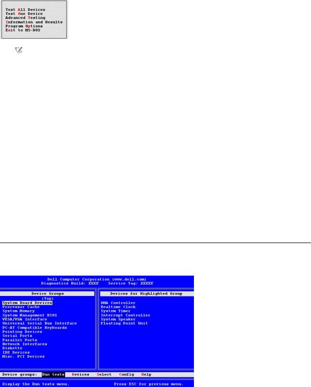
The computer reboots and the Dell logo screen appears, followed by a message telling you that the diagnostics is loading. When the diagnostics load, the following Diagnostics Main Menu screen appears:
NOTE: To change the boot sequence, repeat steps 1 through 6, set the boot sequence to fit your needs, and restart your computer.
7.Select an option from the Diagnostics Main Menu screen by pressing the upor down-arrow key to highlight the option and pressing <Enter>, or press the key that corresponds to the highlighted letter in the option title.
•Test All Devices — Performs quick or extensive tests on all devices.
•Test One Device — Performs quick or extensive tests on a single device after you select it from a list of device groups. After you select Test One Device, press <F1> for more information about a test.
•Advanced Testing — Allows you to modify the parameters of a test, select a group of tests to perform, and access additional information about Advanced Testing.
•Information and Results — Provides test results, test errors, version numbers of subtests, and additional information on the Dell Diagnostics.
•Program Options — Allows you to change the settings of the Dell Diagnostics.
•Exit to MS-DOS — Exits to the MS-DOS® prompt.
8.Select Quick Tests from the Test All Devices or Test One Device option to perform a quick check of your computer or a specific device.
Quick Tests runs only the subtests that run fast and do not require user interaction. Dell recommends that you select Quick Tests first to increase your chance of locating the problem quickly.
9.Select Extended Tests from the Test All Devices or Test One Device option for a thorough check of your computer or to check a particular area of your computer.
10.Select the Advanced Testing option to customize your test(s).
11.Remove the ResourceCD from the CD-ROM drive when you have finished running the Dell Diagnostics.
Advanced Testing
When you select Advanced Testing from the Diagnostics Main Menu screen, the following advanced testing screen appears.
Information in the Advanced Testing screen is presented as follows:

•Device Groups — Lists the diagnostic test groups in the order they run if you select All from the Run tests menu option To select a test device group, press the upor down-arrow key to highlight the group.
NOTE: The diagnostics may not list in the Device Groups area the names of all components or devices that are part of your computer system. For example, it may not list a printer even though it is connected to your computer. However, the parallel port to which the printer is connected appears in the Device Groups list. You can test your printer connection in the Parallel Ports tests.
•Devices for Highlighted Group — Lists the computer's current hardware
•Device groups: menu bar — Contains the options Run tests, Devices, Select, Config, and Help.
To select a menu option, press the leftor right-arrow key to highlight the option and press <Enter>, or press the key that corresponds to the highlighted letter in the category title.
For more information on using the Advanced Testing screen, select the Help menu option.
NOTE: The options displayed on your screen should reflect the hardware configuration of your computer.
Advanced Testing Help Menu
The Help options and a description of their functions are presented in the following table.
Help Option |
Description |
|
|
Menu |
Describes the Advanced Testing screen, the Device Groups, and the diagnostic menus and commands and gives |
|
instructions on how to use them |
|
|
Keys |
Explains the functions of all keystrokes that can be used in the Dell Diagnostics |
|
|
Device Group |
Describes the highlighted group in the Device Groups list on the main menu and provides reasons for using certain |
|
tests |
|
|
Device |
Describes the highlighted device in the Device Groups list on the Advanced Testing screen |
|
|
Test |
Describes the test procedure for each highlighted test group subtest |
|
|
Versions |
Lists the version numbers of the subtests |
|
|
Back to Contents Page
Back to Contents Page
Diskette, Tape, and CD-ROM Drives: Dell™ OptiPlex™ GX300 System User's Guide
To install a diskette, tape, or CD-ROM drive in a 5.25-inch drive bay, perform the following steps.
CAUTION: Before you remove the computer cover, see "Safety First—For You and Your Computer."
1.Unpack the drive and prepare it for installation.
NOTICE: Ground yourself by touching an unpainted metal surface on the back of the computer.
Check the documentation that accompanied the drive to verify that the drive is configured for your computer system. Change any settings necessary for your configuration.
2.If you are installing an enhanced integrated drive electronics (EIDE) drive, configure the drive for the Cable Select setting as described in the documentation that accompanied your drive.
3.Remove the computer cover as instructed in "Removing and Replacing the Computer Cover."
4.Remove the front bezel as instructed in "Removing and Replacing the Front Bezel."
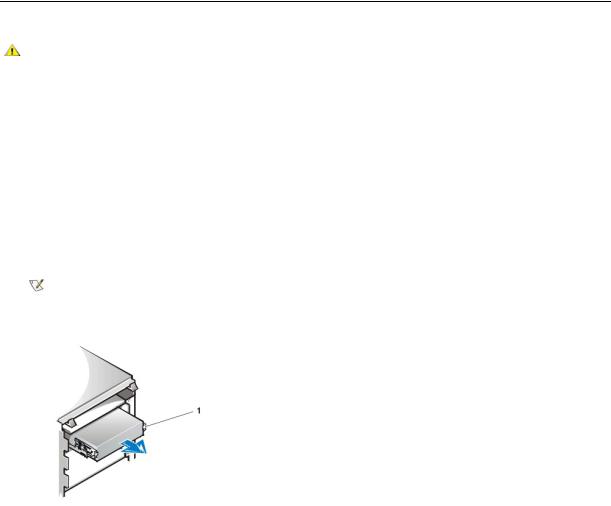
5.Remove the drive bracket from the bay you want to use.
Squeeze the metal tabs that extend from each side of the drive bracket toward each other, and pull the bracket out of the bay (see Figure 1).
NOTE: For easier access inside the chassis, you may want to rotate the power supply out of the way temporarily. To do so, see "Rotating the Power Supply Away From the System Board."
Figure 1. Removing a Drive
1 Bracket tabs (2)
If a drive is already installed in the bay and you are replacing it, disconnect the DC power cable and interface cable from the back of the drive before sliding the bracket out of the bay. To remove the old drive from the bracket, turn the drive/bracket assembly upside down and unscrew the four screws that secure the drive to the bracket (see Figure 2).
6.Attach the drive bracket to the new drive.
Turn the drive upside down, and locate the four screw holes around its perimeter. Fit the bracket over the drive, and then tilt the front of the drive up so that the bracket drops down into place. To ensure proper installation, all screw holes should be aligned and the tabs on the front of the bracket should be flush with the front of the drive (see Figure 2).
Figure 2. Attaching the Drive Bracket to the New Drive

1 Metal tab
2 Drive bracket
3 Screws (4)
To further ensure proper positioning of the drive in the chassis, insert and tighten all four screws in the order in which the holes are numbered (the holes are marked "1" through "4").
7. Slide the new drive into the drive bay until the drive snaps securely into place (see Figure 3).
Make sure that both bracket tabs snap into place in the drive bay.
Figure 3. Inserting the New Drive Into the Drive Bay
1 Drive
8.Connect a DC power cable to the power input connector on the back of the drive (see Figure 4).
9.Connect the appropriate interface cable to the interface connector on the back of the drive (see Figure 4).
If your system came with an EIDE CD-ROM or tape drive, use the spare connector on the existing interface cable. Otherwise, use the EIDE interface cable provided in the drive kit.
NOTICE: You must match the colored strip on the cable with pin 1 on the drive's interface connector to avoid possible damage to your system.
Figure 4. Attaching Diskette Drive or Tape Drive Cables

1 Interface connector
2 Power input connector
3 DC power cable
4 Interface cable
10.For an EIDE tape drive or CD-ROM drive, connect the other end of the interface cable to the interface connector labeled "IDE2" on the system board.
For a diskette drive, connect the cable from the drive to the interface connector labeled "DSKT" on the system board. Check all cable connections. Fold cables out of the way to provide airflow for the fan and cooling vents.
11.If the 5.25-inch drive bay was previously empty, remove the front-panel insert from the front bezel.
Hold the bezel with the inside facing toward you and press each end of the insert with your thumbs until it snaps free of the bezel.
12.Replace the front bezel.
13.Replace the computer cover, reconnect your computer and peripherals to their power sources, and turn them on.
14.Update your system configuration information in System Setup.
For a diskette drive, update Diskette Drive A or Diskette Drive B to reflect the size and capacity of your new diskette drive. For EIDE CD-ROM and tape drives, set the appropriate Secondary Drive 0 or Secondary Drive 1 to Auto.
15.Verify that your system works correctly by running the Dell Diagnostics.
NOTE: Tape drives sold by Dell come with their own operating software and documentation. After you install a tape drive, refer to the documentation that came with the drive for instructions on installing and using the tape drive software.
Back to Contents Page
Back to Contents Page
Expansion Cards: Dell™ OptiPlex™ GX300 System User's Guide
Overview |
Removing an Expansion Card |
Installing an Expansion Card
Overview
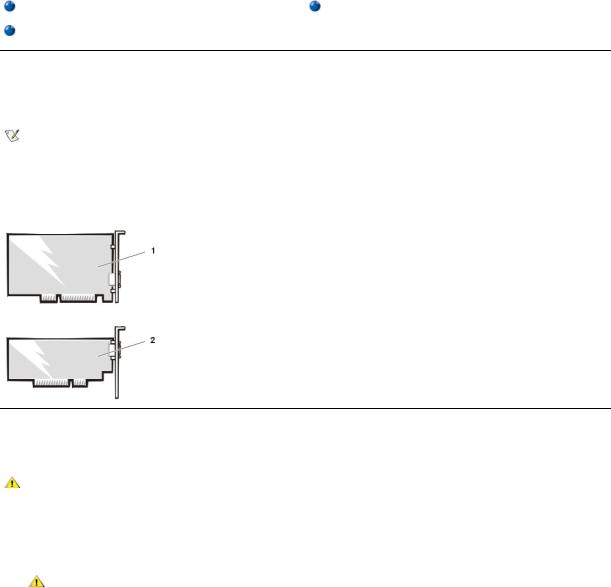
The system accommodates up to six expansion cards, including up to five 32-bit Peripheral Component Interconnect (PCI) expansion cards and a 32-bit accelerated graphics port (AGP) card. (See Figure 1 for examples of these cards.)
NOTES: In order to meet PC99 requirements, your Dell system uses only PCI expansion slots. Industry-Standard Architecture (ISA) expansion cards are not supported.
Before disconnecting a peripheral from the system or removing a component from the system board, verify that the standby power lightemitting diode (LED) on the system board has turned off. For the location of this LED, see Figure 3 in "Inside Your Computer."
Figure 1. Expansion Cards
132-bit PCI expansion card
232-bit AGP card
Installing an Expansion Card
To install an expansion card, perform the following steps.
CAUTION: Before you remove the computer cover, see "Safety First—For You and Your Computer."
1.Prepare the expansion card for installation, and remove the computer cover according to the instructions in "Removing and Replacing the Computer Cover."
See the documentation that came with the expansion card for information on configuring the card, making internal connections, or otherwise customizing it for your system.
CAUTION: Some network cards automatically start up the system when they are connected. To guard against electrical shock, be sure to unplug your computer from its electrical outlet before installing any expansion cards.
2.Remove the AGP card brace according to the instructions in "Removing and Replacing the AGP Card Brace."
3.Unscrew and remove the metal filler bracket that covers the card-slot opening for the expansion slot you intend to use (see Figure 2). Save the screw to use when installing the expansion card later in this procedure.
Figure 2. Removing the Filler Bracket
1 Filler bracket
4. Insert the expansion card into the expansion-card connector.
If the expansion card is full-length, insert the front end of the card into the corresponding card guide on the inside front of the chassis as you insert the card into its connector. Insert the card's edge connector firmly into the expansion-card slot. Gently rock the card into the connector until it is fully seated (see Figure 3).
Figure 3. Installing an Expansion Card
1Expansion card
2Expansioncard connector
3Card edge connector
5.When the card is firmly seated in the connector, secure the card's mounting bracket to the chassis with the screw you removed in step 2.
6.Connect any cables that should be attached to the card.
See the documentation for the card for information about the card's cable connections.
If you are installing the entry-level OptiPlex™ sound card, disconnect the internal speaker cable from the control panel at the front of the chassis and reconnect it to the INT SPKR connector on the sound card. You may have to route the speaker cable through a hole in the front of the chassis in order to reach the sound card connector.
7.Replace the AGP card brace.
8.Replace the computer cover, and reconnect your computer and peripherals to their power sources and turn them on.
NOTE: After you remove and replace the cover, the chassis intrusion detector will cause the following message to be displayed at the next system start-up:
ALERT! Cover was previously removed.
9.To reset the chassis intrusion detector, enter System Setup and reset Chassis Intrusion to Enabled or Enabled-Silent. See "Chassis Intrusion" for instructions.
NOTE: If a setup password has been assigned by someone else, contact your network administrator for information on resetting the chassis intrusion detector.
While in System Setup, if you installed an entry-level OptiPlex sound card, change the setting for Sound to Off.
Removing an Expansion Card
To remove an expansion card, perform the following steps.

CAUTION: Before you remove the computer cover, see "Safety First—For You and Your Computer."
1.Remove the computer cover according to the instructions in "Removing and Replacing the Computer Cover."
2.Remove the AGP card brace according to the instructions in "Removing and Replacing the AGP Card Brace."
3.If necessary, disconnect any cables connected to the card.
4.Unscrew the mounting bracket of the card you want to remove.
5.Grasp the card by its outside corners, and ease it out of its connector.
6.If you are removing the card permanently, install a metal filler bracket over the empty card-slot opening.
NOTE: Installing filler brackets over empty card-slot openings is necessary to maintain Federal Communications Commission (FCC) certification of the system. The brackets also keep dust and dirt out of your computer.
7.Replace the AGP card brace.
8.Replace the computer cover, and reconnect your computer and peripherals to their power sources and turn them on.
NOTE: After you remove and replace the cover, the chassis intrusion detector will cause the following message to be displayed at the next system start-up:
ALERT! Cover was previously removed.
9.To reset the chassis intrusion detector, enter System Setup and reset Chassis Intrusion to Enabled or Enabled-Silent. See "Chassis Intrusion" for instructions.
NOTE: If a setup password has been assigned by someone else, contact your network administrator for information on resetting the chassis intrusion detector.
Back to Contents Page

Back to Contents Page
External Components: Dell™ OptiPlex™ GX300 System User's Guide
Overview |
Troubleshooting I/O Ports |
Troubleshooting the Monitor |
Troubleshooting Basic I/O Functions |
Troubleshooting the Keyboard |
Troubleshooting a Parallel Printer |
Troubleshooting the Mouse |
Troubleshooting a Serial I/O Device |
|
|
Overview
This section provides troubleshooting procedures for equipment that connects directly to the input/output (I/O) panel of your computer, such as your monitor, keyboard, mouse, or printer. Before performing any of the procedures in this section, see "Checking Connections and Switches." Then perform the troubleshooting procedures for the equipment that is malfunctioning.
You need a copy of the Dell ResourceCD to perform the procedures in this section.
Before running the Dell Diagnostics, make sure that your system is set to boot from the CD-ROM drive. See "Starting the Dell Diagnostics" for complete instructions.
Troubleshooting the Monitor
Troubleshooting video problems involves determining which of the following is the source of the problem:
•Monitor or monitor interface cable
•Video controller
The procedures in this section troubleshoot problems with the monitor and the monitor interface cable only.
If information on the monitor screen is displayed incorrectly or not at all, perform each of the following steps in the order indicated until the problem is resolved:
1.Turn on the system, including any attached peripherals.
2.Adjust the switches and controls as specified in the monitor's documentation to correct the video image, including the horizontal and vertical position and size.
3.Start the Dell Diagnostics by inserting the Dell ResourceCD and rebooting the system.
4.Run the Video test group.
5.Turn off the system and disconnect it from the electrical outlet. Swap the monitor with one of the same type that is working, and reconnect the system to an electrical outlet.
6.Reboot the system, and run the Video test group again.
7.If the tests complete successfully, the original monitor was faulty. If the tests still fail, the video controller on the system board may be faulty. See "Getting Help" for instructions on obtaining technical assistance.
Troubleshooting the Keyboard
This procedure determines what kind of keyboard problem you have. If a system error message indicates a keyboard problem when you start the computer system or if the keyboard does not operate as expected, perform the following steps in the order indicated until the problem is resolved:
1.If the keyboard or its cable shows signs of physical damage or if the keys do not work, replace the keyboard with a working keyboard.
2.Start the Dell Diagnostics by inserting the Dell ResourceCD and rebooting the system.
3.Run the Keyboard test group.
4.If the Keyboard Interactive Test fails, replace the keyboard.
5.If the Keyboard Controller Test fails, the system board may be faulty. See "Getting Help" for instructions on obtaining technical assistance.

Troubleshooting the Mouse
This procedure determines what kind of mouse problem you have. If a system error message indicates a mouse problem when you start the computer system or if the mouse does not operate as expected, perform the following steps in the order indicated until the problem is resolved:
1.Clean the mouse as instructed in your mouse documentation.
Most mice have a ball that can be removed and cleaned of debris by turning the mouse upside down and removing a cover on the bottom of the mouse. Also remove any lint or other debris that has accumulated on the bottom of the mouse.
2.If the mouse or its cable shows signs of physical damage or if the buttons do not work, replace the mouse with a working mouse.
3.Start the Dell Diagnostics by inserting the Dell ResourceCD and rebooting the system.
4.Run the Mouse Test.
5.If the Mouse Test fails, the system board may be faulty. See "Getting Help" for instructions on obtaining technical assistance.
Troubleshooting I/O Ports
This section provides a procedure for troubleshooting the ports on your computer's I/O panel and the equipment connected to them, such as a printer, scanner, or other peripheral device.
You can also use this procedure to test I/O ports on expansion cards. However, you should first complete the procedures in "Troubleshooting Expansion Cards" to verify that the card is configured and installed correctly.
If a system error message indicates a port problem or if equipment connected to a port seems to perform incorrectly or not at all, the source of the problem may be any of the following:
•A faulty connection between the I/O port and the peripheral device
•A faulty cable between the I/O port and the peripheral device
•A faulty peripheral device
•Incorrect settings in System Setup
•Incorrect settings in the system's configuration files
•Faulty I/O port logic on the system board
NOTE: With certain modems installed, the Serial Port test group subtests may fail because the modem appears to the diagnostics as a serial port, but it cannot be tested as a serial port. If you have a modem installed and you experience a serial port test failure, remove the modem and run the diagnostic tests again.
Troubleshooting Basic I/O Functions
If a system error message indicates an I/O port problem or the device connected to the port does not function properly, follow these steps in the order indicated until the problem is resolved:
1.Enter System Setup and verify that the settings for the Serial Port 1, Serial Port 2, and Parallel Port options are set to Auto.
2.Start the Dell Diagnostics by inserting the Dell ResourceCD and rebooting the system.
3.Run the Serial/ Infrared Ports test group and/or the Parallel Ports test group.
If any of the tests fail, the system board may be faulty. See "Getting Help" for instructions on obtaining technical assistance.
If the problem persists, go to "Troubleshooting a Parallel Printer" or "Troubleshooting a Serial I/O Device," depending on which device appears to be malfunctioning.
Troubleshooting a Parallel Printer
If the information in "Troubleshooting Basic I/O Functions" indicates that the problem is with a parallel printer, perform the following steps in the order indicated until the problem is resolved:
1. Reinstall the printer device driver.

See the documentation for the printer and for your operating system for instructions on reinstalling the printer driver.
2.Turn off the parallel printer and computer, replace the parallel printer interface cable with a known working cable, and turn on the parallel printer and computer.
If the problem is resolved, the original printer cable was faulty.
3.Run the parallel printer's self-test.
If the test fails, the printer is faulty.
If the problem still is not resolved, the system board may be faulty. See "Getting Help" for instructions on obtaining technical assistance.
Troubleshooting a Serial I/O Device
If the information in "Troubleshooting Basic I/O Functions" indicates that the problem is with a device connected to one of the serial ports, perform the following steps in the order indicated until the problem is resolved:
1.Attach the serial device to the other serial port (for example, if it is currently connected to serial port 1, attach the device to serial port 2).
If the problem is resolved, the serial port on the system board is faulty. See "Getting Help" for instructions on obtaining technical assistance.
2.If the faulty device has a detachable serial cable, replace the serial cable. If the problem is resolved, the serial cable was faulty.
3.Replace the faulty serial device.
If the problem is still not resolved, the system board may be faulty. See "Getting Help" for instructions on obtaining technical assistance.
Back to Contents Page

Back to Contents Page
Getting Help: Dell™ OptiPlex™ GX300 System User's Guide
Help Overview
Contacting Dell
Back to Contents Page

Back to Contents Page
Hard-Disk Drives: Dell™ OptiPlex™ GX300 System User's Guide
Installing an EIDE Hard-Disk Drive
Installing SCSI Devices
Installing an EIDE Hard-Disk Drive
Up to two enhanced integrated drive electronics (EIDE) drives (one of which must be 1 inch high or less) can be installed in the hard-disk drive bracket below the drive cage. The first EIDE drive is installed in the 1-inch (lower) drive bay labeled "HD1"; a second drive is installed in the 1.6- inch bay labeled "HD2."
EIDE Drive Addressing
All EIDE devices should be configured for the Cable Select jumper position, which assigns master and slave status to devices by their position on the interface cable. When two EIDE devices are connected to a single EIDE interface cable and are configured for the Cable Select jumper position, the device attached to the last connector on the interface cable is the master or boot device (drive 0), and the device attached to the middle connector on the interface cable is the slave device (drive 1). Refer to the drive documentation in your upgrade kit for information on setting devices to the Cable Select jumper position.
With the two EIDE interface connectors on the system board, your system can support up to four EIDE devices. EIDE hard-disk drives should be connected to the EIDE interface connector labeled "IDE1." EIDE tape drives and CD-ROM drives should be connected to the EIDE interface connector labeled "IDE2."
Installing an EIDE Hard-Disk Drive in the Hard-Disk Drive Bracket
To install an EIDE hard-disk drive in the hard-disk drive bracket, perform the following steps.
CAUTION: Before you remove the computer cover, see "Safety First — For You and Your Computer."
1.If you are replacing a hard-disk drive that contains data you want to keep, be sure to make a backup of your files before you begin this procedure.
2.Prepare the drive for installation.
NOTICE: Ground yourself by touching an unpainted metal surface on the back of the computer.
NOTICE: When you unpack the drive, do not set it on a hard surface, which may damage the drive. Instead, set the drive on a surface such as a foam pad that will sufficiently cushion it.
Check the documentation for the drive to verify that it is configured for your computer system.
3.Remove the computer cover as instructed in "Removing and Replacing the Computer Cover."
4.Remove the drive bracket from the chassis.
If a hard-disk drive is already installed in the drive bracket, disconnect the DC power cable and EIDE cable from the drive. Remove the screw securing the hard-disk drive bracket to the drive cage in the chassis.
Grasp the bracket, and rotate it outward from the chassis until the sliding tab clears the slide rail on the drive cage (see Figure 1). Lift the bracket up slightly to free its hinge tabs from the chassis slots.
Figure 1. Removing the Hard-Disk Drive Bracket

1 Drive-cage slide rail
2 Chassis slots
3 Hinge tabs
4 Sliding tab
5.Slide the drive into the chosen bay of the bracket, oriented so that the connectors on the back of the drive will face the back of the chassis when the bracket is reinstalled (see Figure 2).
6.Align the four screw holes of the drive and bracket. Insert and tighten the screws that came with your upgrade kit.
If you are installing a drive in the 1.6-inch bay, use the four screw holes in the side of the bracket (see Figure 2). If you are installing a drive in the 1-inch bay, use the four screw holes in the bottom of the bracket.
Figure 2. Inserting a 1.6-Inch Hard-Disk Drive in the Bracket
1 1.6-inch drive
2 Drive bracket
3 Screws (4)
4 Sliding tab
7. Reinstall the hard-disk drive bracket in the chassis (see Figure 3).
Insert the bracket's hinge tabs into the chassis slots so that the tabs hook over the slots. Then rotate the bracket toward the drive cage, and fit the bracket's sliding tab on the drive-cage slide rail. Slide the bracket into place. Reinstall the screw you removed in step 4.
Figure 3. Inserting the Drive Bracket in the Chassis
 Loading...