


 Loading...
Dell Precision 7540
Service Manual
Regulatory Model: P74F
Regulatory Type: P74F002
Notes, cautions, and warnings

 NOTE: A NOTE indicates important information that helps you make better use of your product.

 CAUTION: A CAUTION indicates either potential damage to hardware or loss of data and tells you how to avoid the problem.
 WARNING: A WARNING indicates a potential for property damage, personal injury, or death.
© 2019 Dell Inc. or its subsidiaries. All rights reserved. Dell, EMC, and other trademarks are trademarks of Dell Inc. or its subsidiaries. Other trademarks may be trademarks of their respective owners.
2019 - 05
Rev. A00

Contents
1 Working on your computer............................................................................................................................. |
6 |
Safety instructions............................................................................................................................................................. |
6 |
Turning o€ your computer — Windows 10..................................................................................................................... |
6 |
Before working inside your computer.............................................................................................................................. |
6 |
After working inside your computer................................................................................................................................. |
7 |
2 Technology and components.......................................................................................................................... |
8 |
HDMI 2.0............................................................................................................................................................................. |
8 |
HDMI 2.0 Features....................................................................................................................................................... |
8 |
Advantages of HDMI................................................................................................................................................... |
8 |
USB features...................................................................................................................................................................... |
9 |
USB 3.0/USB 3.1 Gen 1 (SuperSpeed USB)............................................................................................................. |
9 |
Speed............................................................................................................................................................................. |
9 |
Applications................................................................................................................................................................. |
10 |
Compatibility................................................................................................................................................................ |
10 |
USB Type-C........................................................................................................................................................................ |
11 |
Alternate Mode............................................................................................................................................................ |
11 |
USB Power Delivery.................................................................................................................................................... |
11 |
USB Type-C and USB 3.1............................................................................................................................................ |
11 |
Thunderbolt over USB Type-C.................................................................................................................................. |
11 |
Thunderbolt 3 over USB Type-C.............................................................................................................................. |
12 |
Key Features of Thunderbolt 3 over USB Type-C ................................................................................................. |
12 |
Thunderbolt Icons....................................................................................................................................................... |
12 |
3 Removing and installing components............................................................................................................ |
13 |
Recommended tools......................................................................................................................................................... |
13 |
Screw size list.................................................................................................................................................................... |
13 |
SD card.............................................................................................................................................................................. |
14 |
Removing SD card...................................................................................................................................................... |
14 |
Installing SD card........................................................................................................................................................ |
15 |
Base cover......................................................................................................................................................................... |
16 |
Removing the base cover.......................................................................................................................................... |
16 |
Installing the base cover............................................................................................................................................. |
17 |
Battery............................................................................................................................................................................... |
18 |
Lithium-ion battery precautions................................................................................................................................ |
18 |
Removing the battery................................................................................................................................................ |
19 |
Installing the battery.................................................................................................................................................. |
20 |
Keyboard........................................................................................................................................................................... |
22 |
Removing the keyboard............................................................................................................................................ |
22 |
Installing the keyboard............................................................................................................................................... |
26 |
Primary memory module................................................................................................................................................. |
28 |
Removing the primary memory module.................................................................................................................. |
28 |
Installing the primary memory module.................................................................................................................... |
29 |
Contents 3
Secondary memory module............................................................................................................................................ |
30 |
Removing the secondary memory module............................................................................................................. |
30 |
Installing the secondary memory module................................................................................................................ |
31 |
WWAN card...................................................................................................................................................................... |
32 |
Removing WWAN card............................................................................................................................................. |
32 |
Installing the WWAN card......................................................................................................................................... |
33 |
WLAN card....................................................................................................................................................................... |
34 |
Removing the WLAN card........................................................................................................................................ |
34 |
Installing the WLAN card.......................................................................................................................................... |
35 |
SIM card............................................................................................................................................................................ |
36 |
Removing SIM card................................................................................................................................................... |
36 |
Installing SIM card...................................................................................................................................................... |
37 |
Solid State Drive............................................................................................................................................................... |
38 |
Removing the M.2 Solid State Drive—SSD module............................................................................................. |
38 |
Installing the M.2 SSD module.................................................................................................................................. |
41 |
2.5" Hard drive.................................................................................................................................................................. |
43 |
Removing the hard drive assembly.......................................................................................................................... |
43 |
Installing the hard drive assembly............................................................................................................................ |
44 |
Hard drive interposer board............................................................................................................................................ |
45 |
Removing the hard drive interposer board............................................................................................................. |
45 |
Installing the hard drive interposer board................................................................................................................ |
46 |
Coin-cell battery............................................................................................................................................................... |
47 |
Removing the coin cell battery................................................................................................................................. |
47 |
Installing the coin cell battery................................................................................................................................... |
48 |
Power connector port..................................................................................................................................................... |
49 |
Removing the power connector port...................................................................................................................... |
49 |
Installing the power connector port......................................................................................................................... |
51 |
Palm rest........................................................................................................................................................................... |
53 |
Removing the palmrest............................................................................................................................................. |
53 |
Installing the palmrest............................................................................................................................................... |
56 |
Touchpad button.............................................................................................................................................................. |
58 |
Removing the Touchpad buttons............................................................................................................................. |
58 |
Installing the Touchpad button................................................................................................................................. |
59 |
Smart card cage............................................................................................................................................................... |
60 |
Removing the smart card cage................................................................................................................................ |
60 |
Installing the smart card cage................................................................................................................................... |
61 |
Speaker............................................................................................................................................................................. |
62 |
Removing the speakers ............................................................................................................................................ |
62 |
Installing the speakers............................................................................................................................................... |
63 |
LED board......................................................................................................................................................................... |
64 |
Removing the LED board.......................................................................................................................................... |
64 |
Installing the LED board............................................................................................................................................ |
65 |
Heat sink .......................................................................................................................................................................... |
66 |
Removing the heat sink assembly........................................................................................................................... |
66 |
Installing the heat sink assembly.............................................................................................................................. |
69 |
Graphics card.................................................................................................................................................................... |
71 |
Removing the graphics card...................................................................................................................................... |
71 |
4 Contents
Installing the graphics card....................................................................................................................................... |
72 |
System board.................................................................................................................................................................... |
73 |
Removing the system board..................................................................................................................................... |
73 |
Installing the system board....................................................................................................................................... |
76 |
Display assembly.............................................................................................................................................................. |
79 |
Removing the display assembly................................................................................................................................ |
79 |
Installing the display assembly.................................................................................................................................. |
82 |
Display bezel..................................................................................................................................................................... |
85 |
Removing the display bezel...................................................................................................................................... |
85 |
Installing the display bezel......................................................................................................................................... |
86 |
Display panel..................................................................................................................................................................... |
87 |
Removing the display panel....................................................................................................................................... |
87 |
Installing the display panel......................................................................................................................................... |
88 |
Display hinges................................................................................................................................................................... |
89 |
Removing the display hinge...................................................................................................................................... |
89 |
Installing the display hinge........................................................................................................................................ |
90 |
Camera............................................................................................................................................................................... |
91 |
Removing the camera................................................................................................................................................ |
91 |
Installing the camera.................................................................................................................................................. |
92 |
eDP cable.......................................................................................................................................................................... |
93 |
Removing the eDP cable........................................................................................................................................... |
93 |
Installing the eDP cable............................................................................................................................................. |
94 |
Display bracket................................................................................................................................................................. |
95 |
Removing the display support bracket.................................................................................................................... |
95 |
Installing the display support bracket...................................................................................................................... |
96 |
4 Troubleshooting........................................................................................................................................... |
98 |
Enhanced Pre-Boot System Assessment — ePSA diagnostics................................................................................ |
98 |
Running the ePSA Diagnostics................................................................................................................................. |
98 |
Diagnostic LED................................................................................................................................................................. |
98 |
Battery status LED.......................................................................................................................................................... |
99 |
5 Getting help............................................................................................................................................... |
100 |
Contacting Dell............................................................................................................................................................... |
100 |
Contents 5

1
Working on your computer
Safety instructions
Use the following safety guidelines to protect your computer from potential damage and to ensure your personal safety. Unless otherwise noted, each procedure included in this document assumes that the following conditions exist:
•You have read the safety information that shipped with your computer.
•A component can be replaced or, if purchased separately, installed by performing the removal procedure in reverse order.
WARNING: Disconnect all power sources before opening the computer cover or panels. After you finish working inside the computer, replace all covers, panels, and screws before connecting to the power source.
WARNING: Before working inside your computer, read the safety information that shipped with your computer. For additional safety best practices information, see the Regulatory Compliance Homepage
CAUTION: Many repairs may only be done by a certified service technician. You should only perform troubleshooting and simple repairs as authorized in your product documentation, or as directed by the online or telephone service and support team. Damage due to servicing that is not authorized by Dell is not covered by your warranty. Read and follow the safety instructions that came with the product.
CAUTION: To avoid electrostatic discharge, ground yourself by using a wrist grounding strap or by periodically touching an unpainted metal surface at the same time as touching a connector on the back of the computer.
CAUTION: Handle components and cards with care. Do not touch the components or contacts on a card. Hold a card by its edges or by its metal mounting bracket. Hold a component such as a processor by its edges, not by its pins.
CAUTION: When you disconnect a cable, pull on its connector or on its pull-tab, not on the cable itself. Some cables have connectors with locking tabs; if you are disconnecting this type of cable, press in on the locking tabs before you disconnect the cable. As you pull connectors apart, keep them evenly aligned to avoid bending any connector pins. Also, before you connect a cable, ensure that both connectors are correctly oriented and aligned.

 NOTE: The color of your computer and certain components may appear differently than shown in this document.
Turning off your computer — Windows 10
CAUTION: To avoid losing data, save and close all open files and exit all open programs before you turn off your computer or remove the side cover.
1Click or tap  .
.
2Click or tap  and then click or tap Shut down.
NOTE: Ensure that the computer and all attached devices are turned off. If your computer and attached devices did not automatically turn off when you shut down your operating system, press and hold the power button for about 6 seconds to turn them off.
Before working inside your computer
1Ensure that your work surface is flat and clean to prevent the computer cover from being scratched.
2Turn o€ your computer.
3Disconnect all network cables from the computer (if available).
6 Working on your computer

CAUTION: If your computer has an RJ45 port, disconnect the network cable by first unplugging the cable from your computer.
4Disconnect your computer and all attached devices from their electrical outlets.
5Open the display.
6Press and hold the power button for few seconds, to ground the system board.
CAUTION: To guard against electrical shock unplug your computer from the electrical outlet before performing Step # 8.
CAUTION: To avoid electrostatic discharge, ground yourself by using a wrist grounding strap or by periodically touching an unpainted metal surface at the same time as touching a connector on the back of the computer.
7 Remove any installed ExpressCards or Smart Cards from the appropriate slots.
After working inside your computer
After you complete any replacement procedure, ensure that you connect external devices, cards, and cables before turning on your computer.
CAUTION: To avoid damage to the computer, use only the battery designed for this particular Dell computer. Do not use batteries designed for other Dell computers.
1Connect any external devices, such as a port replicator or media base, and replace any cards, such as an ExpressCard.
2Connect any telephone or network cables to your computer.
CAUTION: To connect a network cable, first plug the cable into the network device and then plug it into the computer.
3Connect your computer and all attached devices to their electrical outlets.
4Turn on your computer.
Working on your computer |
7 |

2
Technology and components
This chapter details the technology and components available in the system.
Topics:
•HDMI 2.0
•USB features
•USB Type-C
HDMI 2.0
This topic explains the HDMI 2.0 and its features along with the advantages.
HDMI (High-Definition Multimedia Interface) is an industry-supported, uncompressed, all-digital audio/video interface. HDMI provides an interface between any compatible digital audio/video source, such as a DVD player, or A/V receiver and a compatible digital audio and/or video monitor, such as a digital TV (DTV). The intended applications for HDMI TVs, and DVD players. The primary advantage is cable reduction and content protection provisions. HDMI supports standard, enhanced, or high-definition video, plus multichannel digital audio on a single cable.
HDMI 2.0 Features
•HDMI Ethernet Channel - Adds high-speed networking to an HDMI link, allowing users to take full advantage of their IP-enabled devices without a separate Ethernet cable
•Audio Return Channel - Allows an HDMI-connected TV with a built-in tuner to send audio data "upstream" to a surround audio system, eliminating the need for a separate audio cable
•3D - Defines input/output protocols for major 3D video formats, paving the way for true 3D gaming and 3D home theater applications
•Content Type - Real-time signaling of content types between display and source devices, enabling a TV to optimize picture settings based on content type
•Additional Color Spaces - Adds support for additional color models used in digital photography and computer graphics
•4K Support - Enables video resolutions far beyond 1080p, supporting next-generation displays that will rival the Digital Cinema systems used in many commercial movie theaters
•HDMI Micro Connector - A new, smaller connector for phones and other portable devices, supporting video resolutions up to 1080p
•Automotive Connection System - New cables and connectors for automotive video systems, designed to meet the unique demands of the motoring environment while delivering true HD quality
Advantages of HDMI
•Quality HDMI transfers uncompressed digital audio and video for the highest, crispest image quality.
•Low -cost HDMI provides the quality and functionality of a digital interface while also supporting uncompressed video formats in a simple, cost-e€ective manner
•Audio HDMI supports multiple audio formats from standard stereo to multichannel surround sound
•HDMI combines video and multichannel audio into a single cable, eliminating the cost, complexity, and confusion of multiple cables currently used in A/V systems
•HDMI supports communication between the video source (such as a DVD player) and the DTV, enabling new functionality
8 Technology and components

USB features
Universal Serial Bus, or USB, was introduced in 1996. It dramatically simplified the connection between host computers and peripheral devices like mice, keyboards, external drivers, and printers.
Let's take a quick look on the USB evolution referencing to the table below.
Table 1. USB evolution |
|
|
|
Type |
Data Transfer Rate |
Category |
Introduction Year |
|
|
|
|
USB 2.0 |
480 Mbps |
High Speed |
2000 |
USB 3.0/USB 3.1 Gen 1 |
5 Gbps |
Super Speed |
2010 |
USB 3.1 Gen 2 |
10 Gbps |
Super Speed |
2013 |
USB 3.0/USB 3.1 Gen 1 (SuperSpeed USB)
For years, the USB 2.0 has been firmly entrenched as the de facto interface standard in the PC world with about 6 billion devices sold, and yet the need for more speed grows by ever faster computing hardware and ever greater bandwidth demands. The USB 3.0/USB 3.1 Gen 1 finally has the answer to the consumers' demands with a theoretically 10 times faster than its predecessor. In a nutshell, USB 3.1 Gen 1 features are as follows:
•Higher transfer rates (up to 5 Gbps)
•Increased maximum bus power and increased device current draw to better accommodate power-hungry devices
•New power management features
•Full-duplex data transfers and support for new transfer types
•Backward USB 2.0 compatibility
•New connectors and cable
The topics below cover some of the most commonly asked questions regarding USB 3.0/USB 3.1 Gen 1.
Speed
Currently, there are 3 speed modes defined by the latest USB 3.0/USB 3.1 Gen 1 specification. They are Super-Speed, Hi-Speed and FullSpeed. The new SuperSpeed mode has a transfer rate of 4.8Gbps. While the specification retains Hi-Speed, and Full-Speed USB mode, commonly known as USB 2.0 and 1.1 respectively, the slower modes still operate at 480Mbps and 12Mbps respectively and are kept to maintain backward compatibility.
USB 3.0/USB 3.1 Gen 1 achieves the much higher performance by the technical changes below:
•An additional physical bus that is added in parallel with the existing USB 2.0 bus (refer to the picture below).
•USB 2.0 previously had four wires (power, ground, and a pair for di€erential data); USB 3.0/USB 3.1 Gen 1 adds four more for two pairs of di€erential signals (receive and transmit) for a combined total of eight connections in the connectors and cabling.
•USB 3.0/USB 3.1 Gen 1 utilizes the bidirectional data interface, rather than USB 2.0's half-duplex arrangement. This gives a 10-fold increase in theoretical bandwidth.
Technology and components |
9 |

With today's ever increasing demands placed on data transfers with high-definition video content, terabyte storage devices, high megapixel count digital cameras etc., USB 2.0 may not be fast enough. Furthermore, no USB 2.0 connection could ever come close to the 480Mbps theoretical maximum throughput, making data transfer at around 320Mbps (40MB/s) — the actual real-world maximum. Similarly, USB 3.0/USB 3.1 Gen 1 connections will never achieve 4.8Gbps. We will likely see a real-world maximum rate of 400MB/s with overheads. At this speed, USB 3.0/USB 3.1 Gen 1 is a 10x improvement over USB 2.0.
Applications
USB 3.0/USB 3.1 Gen 1 opens up the laneways and provides more headroom for devices to deliver a better overall experience. Where USB video was barely tolerable previously (both from a maximum resolution, latency, and video compression perspective), it's easy to imagine that with 5-10 times the bandwidth available, USB video solutions should work that much better. Single-link DVI requires almost 2Gbps throughput. Where 480Mbps was limiting, 5Gbps is more than promising. With its promised 4.8Gbps speed, the standard will find its way into some products that previously weren't USB territory, like external RAID storage systems.
Listed below are some of the available SuperSpeed USB 3.0/USB 3.1 Gen 1 products:
•External Desktop USB 3.0/USB 3.1 Gen 1 Hard Drives
•Portable USB 3.0/USB 3.1 Gen 1 Hard Drives
•USB 3.0/USB 3.1 Gen 1 Drive Docks & Adapters
•USB 3.0/USB 3.1 Gen 1 Flash Drives & Readers
•USB 3.0/USB 3.1 Gen 1 Solid-state Drives
•USB 3.0/USB 3.1 Gen 1 RAIDs
•Optical Media Drives
•Multimedia Devices
•Networking
•USB 3.0/USB 3.1 Gen 1 Adapter Cards & Hubs
Compatibility
The good news is that USB 3.0/USB 3.1 Gen 1 has been carefully planned from the start to peacefully co-exist with USB 2.0. First of all, while USB 3.0/USB 3.1 Gen 1 specifies new physical connections and thus new cables to take advantage of the higher speed capability of the new protocol, the connector itself remains the same rectangular shape with the four USB 2.0 contacts in the exact same location as before. Five new connections to carry receive and transmitted data independently are present on USB 3.0/USB 3.1 Gen 1 cables and only come into contact when connected to a proper SuperSpeed USB connection.
Windows 8/10 will be bringing native support for USB 3.1 Gen 1 controllers. This is in contrast to previous versions of Windows, which continue to require separate drivers for USB 3.0/USB 3.1 Gen 1 controllers.
10 Technology and components
Microsoft announced that Windows 7 would have USB 3.1 Gen 1 support, perhaps not on its immediate release, but in a subsequent Service Pack or update. It is not out of the question to think that following a successful release of USB 3.0/USB 3.1 Gen 1 support in Windows 7, SuperSpeed support would trickle down to Vista. Microsoft has confirmed this by stating that most of their partners share the opinion that Vista should also support USB 3.0/USB 3.1 Gen 1.
USB Type-C
USB Type-C is a new, tiny physical connector. The connector itself can support various exciting new USB standards like USB 3.1 and USB power delivery (USB PD).
Alternate Mode
USB Type-C is a new connector standard that is very small. It is about a third the size of an old USB Type-A plug. This is a single connector standard that every device should be able to use. USB Type-C ports can support a variety of di€erent protocols using “alternate modes,” which allows you to have adapters that can output HDMI, VGA, DisplayPort, or other types of connections from that single USB port
USB Power Delivery
The USB PD specification is also closely intertwined with USB Type-C. Currently, smartphones, tablets, and other mobile devices often use a USB connection to charge. A USB 2.0 connection provides up to 2.5 watts of power — that'll charge your phone, but that's about it. A laptop might require up to 60 watts, for example. The USB Power Delivery specification ups this power delivery to 100 watts. It's bidirectional, so a device can either send or receive power. And this power can be transferred at the same time the device is transmitting data across the connection.
This could spell the end of all those proprietary laptop charging cables, with everything charging via a standard USB connection. You could charge your laptop from one of those portable battery packs you charge your smartphones and other portable devices from today. You could plug your laptop into an external display connected to a power cable, and that external display would charge your laptop as you used it as an external display — all via the one little USB Type-C connection. To use this, the device and the cable have to support USB Power Delivery. Just having a USB Type-C connection doesn't necessarily mean they do.
USB Type-C and USB 3.1
USB 3.1 is a new USB standard. USB 3's theoretical bandwidth is 5 Gbps, while USB 3.1's is 10 Gbps. That's double the bandwidth, as fast as a first-generation Thunderbolt connector. USB Type-C isn't the same thing as USB 3.1. USB Type-C is just a connector shape, and the underlying technology could just be USB 2 or USB 3.0. In fact, Nokia's N1 Android tablet uses a USB Type-C connector, but underneath it's all USB 2.0 — not even USB 3.0. However, these technologies are closely related.
Thunderbolt over USB Type-C
Thunderbolt is a hardware interface that combines data, video, audio, and power in a single connection. Thunderbolt combines PCI Express (PCIe) and DisplayPort (DP) into one serial signal, and additionally provides DC power, all in one cable. Thunderbolt 1 and Thunderbolt 2 use the same connector as miniDP (DisplayPort) to connect to peripherals, while Thunderbolt 3 uses a USB Type-C connector.
Technology and components |
11 |

Figure 1. Thunderbolt 1 and Thunderbolt 3
1Thunderbolt 1 and Thunderbolt 2 (using a miniDP connector)
2Thunderbolt 3 (using a USB Type-C connector)
Thunderbolt 3 over USB Type-C
Thunderbolt 3 brings Thunderbolt to USB Type-C at speeds up to 40 Gbps, creating one compact port that does it all - delivering the fastest, most versatile connection to any dock, display or data device like an external hard drive. Thunderbolt 3 uses a USB Type-C connector/port to connect to supported peripherals.
1Thunderbolt 3 uses USB Type-C connector and cables - It is compact and reversible
2Thunderbolt 3 supports speed up to 40 Gbps
3DisplayPort 1.2 – compatible with existing DisplayPort monitors, devices and cables
4USB Power Delivery - Up to 130W on supported computers
Key Features of Thunderbolt 3 over USB Type-C
1Thunderbolt, USB, DisplayPort and power on USB Type-C on a single cable (features vary between di€erent products)
2USB Type-C connector and cables which are compact and reversible
3Supports Thunderbolt Networking (*varies between di€erent products)
4Supports up to 4K displays
5Up to 40 Gbps

 NOTE: Data transfer speed may vary between different devices.
Thunderbolt Icons
Figure 2. Thunderbolt Iconography Variations
12 Technology and components

3
Removing and installing components
Recommended tools
The procedures in this document require the following tools:
•Phillips #0 screwdriver
•Phillips #1 screwdriver
•Plastic scribe

 NOTE: The #0 screw driver is for screws 0-1 and the #1 screw driver is for screws 2-4
Screw size list
Table 2. Precision 7540
Component |
Screw type |
Quantity |
Image |
|
|
|
|
Keyboard |
M2.0x2.0 |
6 |
|
|
|
|
|
SSD thermal plate |
M2.0x3.0 |
1 per SSD |
|
M.2 SSD card |
|
1 per SSD |
|
HDD Interposer board |
|
2 |
|
WLAN card |
|
1 |
|
WWAN |
|
1 |
|
eDP bracket |
|
2 |
|
Display panel |
|
4 |
|
Power button board |
|
1 |
|
Smart card cage |
|
2 |
|
FPC beam connector |
|
2 |
|
Palmrest |
|
4 |
|
Display support bracket |
|
6 |
|
|
|
|
|
System board |
M2.0x5.0 |
3 |
|
Palmrest |
|
11 |
|
Type-C bracket |
|
3 |
|
LED board |
|
1 |
|
Power connector port |
|
1 |
|
|
|
|
|
Removing and installing components |
13 |

Component |
Screw type |
Quantity |
Image |
|
|
|
|
GPU card |
|
2 |
|
|
|
|
|
4 Cell Battery |
M2.5x3.0 |
2 |
|
6 Cell Battery |
|
3 |
|
HDD assembly |
|
4 |
|
|
|
|
|
Display hinge |
M2.5x3.5 |
6 |
|
|
|
|
|
Hinge cap |
M2.5x4.0 |
4 |
|
Display assembly (bottom) |
|
2 |
|
|
|
|
|
Display assembly (rear) |
M2.5X6.0 |
2 |
|
|
|
|
|
HDD bracket |
M3.0x3.0 |
4 |
|
|
|
|
|
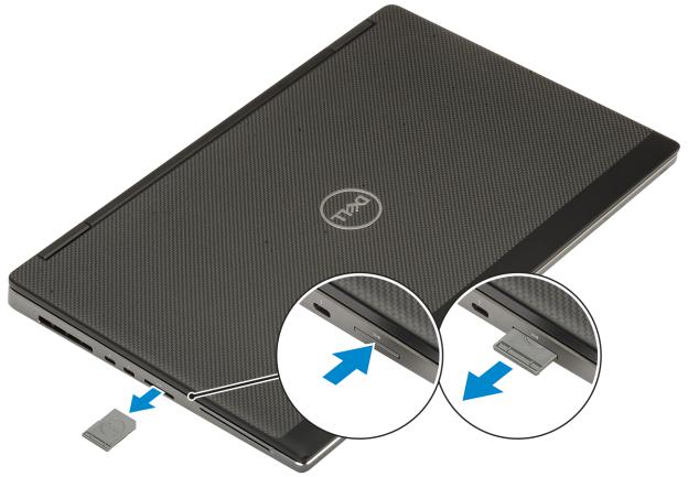
SD card
Removing SD card
1Follow the procedure in Before working inside your computer.
2Press the SD card in to release it from the system.
3Slide the SD card out of the system.
14 Removing and installing components
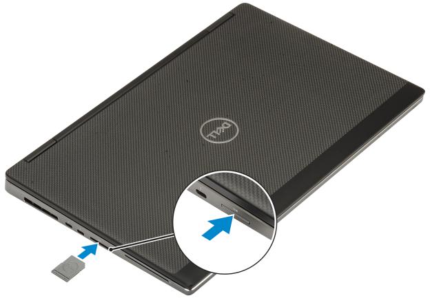
Installing SD card
1 Slide the SD card into its slot until it clicks into place.
Removing and installing components |
15 |
2 Follow the procedure in After working inside your computer.
Base cover
Removing the base cover
1Follow the procedure in Before working inside your computer.
2Remove the SD card.
3To remove the base cover:
aLoosen the 7 captive screws that secure the base cover to the system [1].
bPry open the base cover starting from the two recess point at the top edge of the system [2].
cPry around all the edges of the base cover [3].
dRemove the base cover from the system [4].
16 Removing and installing components

NOTE: While pry open the base cover make sure to use hands or plastic scribe—do not use any other sharp objects as it may damage the chassis
Installing the base cover
1 To install the base cover:
aSlide the base cover into its slot until it clicks into place [1, 2].
bTighten the captive screws to secure the base cover to the system [3].
Removing and installing components |
17 |

2Install the SD card.
3Follow the procedure in After working inside your computer.
Battery
Lithium-ion battery precautions
CAUTION:
•Exercise caution when handling Lithium-ion batteries.
•Discharge the battery as much as possible before removing it from the system. This can be done by disconnecting the AC adapter from the system to allow the battery to drain.
•Do not crush, drop, mutilate, or penetrate the battery with foreign objects.
•Do not expose the battery to high temperatures, or disassemble battery packs and cells.
•Do not apply pressure to the surface of the battery.
•Do not bend the battery.
•Do not use tools of any kind to pry on or against the battery.
•Ensure any screws during the servicing of this product are not lost or misplaced, to prevent accidental puncture or damage to the battery and other system components.
•If the battery gets stuck inside your computer as a result of swelling, do not try to release it as puncturing, bending, or crushing a lithium-ion battery can be dangerous. In such an instance, contact Dell technical support for assistance. See www.dell.com/ contactdell.
•Always purchase genuine batteries from www.dell.com or authorized Dell partners and resellers.
18 Removing and installing components

Removing the battery
1Follow the procedure in Before working inside your computer.
2Remove the:.
aSD card
bbase cover
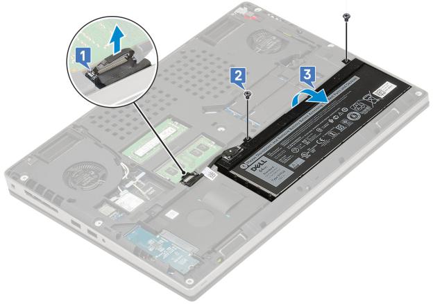
3 To remove the 6-cell battery:
aDisconnect the battery cable from the connector on the battery [1].
bRemove the 3 (M2.5x3.0) screws that secure the battery to the system [2].
cRemove the battery away from the system [3].
4 To remove the 4-cell battery:
aDisconnect the battery cable from the connector on the battery [1].
bRemove the 2 (M2.5x3.0) screws that secure the battery to the system [2].
cRemove the battery away from the system [3].
Removing and installing components |
19 |
Installing the battery
1 To install the 6-cell battery:
aPlace the battery onto its slot in the system [1].
bReplace the 3 (M2.5x3.0) screws to secure the battery to the system [2].
cConnect the battery cable to the connector in the battery [3].
20 Removing and installing components
2 To install the 4-cell battery:
aPlace the battery onto its slot in the system [1].
bReplace the 2 (M2.5x3.0) screws to secure the battery to the system [2].
cConnect the battery cable to the connector in the system board [3].
Removing and installing components |
21 |

3 Install the:
abase cover
bSD card
4 Follow the procedure in After working inside your computer.
Keyboard
Removing the keyboard
1Follow the procedures in Before working inside your computer.
2Remove the:
aSD card
bbase cover
cbattery
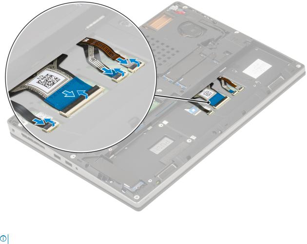
3 To remove the keyboard:
aLift the latch and disconnect the keyboard cable, fingerprint cable and the fingerprint button cable from the connectors on the system board.
22 Removing and installing components

bTurn-over and open the system at 90° angle.
cUsing a plastic scribe pry the keyboard lattice starting from the recess points on the top edge [1,2] and work along the sides and bottom edge of the keyboard lattice.
Removing and installing components |
23 |

d Lift the keyboard lattice away from the system.
24 Removing and installing components

eRemove the 6 (M2.0x2.0) screws that secure the keyboard to the palmrest [1].
fPry the bottom edge of the keyboard and then work along the left and right sides of the keyboard [2,3,4].
g Slide and remove the keyboard from the system.
Removing and installing components |
25 |

Installing the keyboard
1 To Install the keyboard:
a Align the keyboard and route the cables back through to the bottom of the compartment.
bPress and align the keyboard to its compartment working along the left, right and bottom edges [1,2,3].
cReplace the 6 (M2.0x2.0) screws to secure the keyboard to the palmrest [4].
26 Removing and installing components
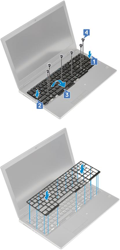
d Align the keyboard lattice to its position on the keyboard and ensure that the keyboard lattice clicks into its place.
eTurn-over the system at 90° angle to access the keyboard cables.
fConnect the keyboard cable, fingerprint cable and fingerprint button cable to the connectors on the system board.
Removing and installing components |
27 |

 NOTE: Ensure that you fold the keyboard data cable in perfect alignment.
2
NOTE: Ensure that you fold the keyboard data cable in perfect alignment.
3 Install the:
abattery
bbase cover
cSD card
4 Follow the procedure in After working inside your computer.
Primary memory module
Removing the primary memory module
1Follow the procedure in Before working inside your computer.
2Remove the:
aSD card
bbase cover
cbattery
3 To remove primary memory module:
aPry the retention clips away from the memory module until it pops up.
bLift the memory module and remove it from the system.
28 Removing and installing components

Installing the primary memory module
1 To Install the primary memory module:
aInsert the memory module into the memory socket.
bPress the clips to secure the memory module to the system board.
Removing and installing components |
29 |

2 Install the:
abattery
bbase cover
cSD card
3 Follow the procedure in After working inside your computer.
Secondary memory module
Removing the secondary memory module
1Follow the procedure in Before working inside your computer.
2Remove the:
aSD card
bbase cover
cbattery
dkeyboard
3 To remove the secondary memory module:
aRemove the single (M2.0x3.0) screw that secures the memory shield [1].
bSlide and lift the memory shield from the memory module on the system [2].
cPry the retention clips away from the memory module until it pops up [3].
dLift the memory module and remove it from the system [4].
30 Removing and installing components
Loading...