


Dell™ OptiPlex™ GX110 System User's Guide
Introduction
Setup and Operation
Drivers and Utilities
System Setup
Installing Upgrades
Troubleshooting
Technical Specifications
NOTE: You can obtain the latest version of this document from the Support section of the Dell Web site at http://www.dell.com.
Models DCP, DCS, DCM, and MMP
Notes, Notices, and Cautions
Throughout this guide, there may be blocks of text printed in bold type or in italic type. These blocks are notes, notices, and cautions, and they are used as follows:
NOTE: A NOTE indicates important information that helps you make better use of your system.
NOTICE: A NOTICE indicates either potential damage to hardware or loss of data and tells you how to avoid the problem.
CAUTION: A CAUTION indicates a potentially hazardous situation which, if not avoided, may result in minor or moderate injury.
Information in this document is subject to change without notice. © 1999 Dell Computer Corporation. All rights reserved.
Reproduction in any manner whatsoever without the written permission of Dell Computer Corporation is strictly forbidden.
Trademarks used in this text: Dell, OptiPlex, OptiFrame, Dell OpenManage, Dimension, Latitude, Inspiron, DellWare, and the DELL logo are trademarks of Dell Computer Corporation; Microsoft, Windows, MS-DOS, and Windows NT are registered trademarks of Microsoft Corporation; Intel and Pentium are registered trademarks of Intel Corporation; 3Com is a registered trademark of 3Com Corporation; IBM and OS/2 are registered trademarks of International Business Machines Corporation; Novell and NetWare are registered trademarks of Novell, Inc. As an ENERGY STAR Partner, Dell Computer Corporation has determined that this product meets the ENERGY STAR guidelines for energy efficiency.
Other trademarks and trade names may be used in this document to refer to either the entities claiming the marks and names or their products. Dell Computer Corporation disclaims any proprietary interest in trademarks and trade names other than its own.
Initial release: 19 Aug 1999
Last revised: 3 Dec 1999
Back to Contents Page
Basic Checks: Dell™ OptiPlex™ GX110 System User's Guide
Overview |
Checking Connections and Switches |
Backing Up Your Files |
Look and Listen |
Basic Checks |
System Setup |
|
|
Overview
If your Dell computer system is not working as expected, and if you are not sure what to do, start your troubleshooting with the procedures in this section. This section guides you through basic steps to solve basic computer problems. It also directs you to further detailed troubleshooting information and procedures to solve more complex problems.
Backing Up Your Files
If your system is behaving erratically, back up your files immediately. If your system has a tape drive installed, see the documentation that came with the tape backup software for instructions on performing a backup operation. Otherwise, see your operating system documentation for information on backing up data files.
Basic Checks
See the following sections in the order indicated until the problem is resolved:
•If your computer is wet or damaged, see "Troubleshooting a Wet Computer" or "Troubleshooting a Damaged Computer."
•Perform the steps in "Checking Connections and Switches."
•Perform the steps in "Look and Listen."
•If your system did not complete the boot (start-up) routine, see "Getting Help."
NOTE: The boot routine is the operating system's attempt to load its files into memory from the boot-up sector on the hard-disk drive or another bootable device.
•If your system displayed a message or emitted a beep code, see "Messages and Codes."
•Verify the settings in System Setup.
•Run the Dell Diagnostics.
Checking Connections and Switches
Improperly set switches and controls and loose or improperly connected cables are the most likely source of problems for your computer, monitor, or other peripheral (such as a printer, keyboard, mouse, or other external equipment).
NOTE: See "Controls and Indicators" and "Connecting Peripheral Devices" for the location of your computer's external connections and switches.
Complete the following steps in the order indicated to check all the connections and switches:
1.Turn off the system, including any attached peripherals (such as the monitor, keyboard, printer, external drives, scanners, or plotters). Disconnect all the AC power cables from their electrical outlets.
2.If your computer is connected to a power strip, turn the power strip off and then on again. If the problem is not resolved, try another power strip or connect the system directly to an electrical outlet to see if the original power strip is faulty.
3.Connect the system to a different electrical outlet.
If doing so corrects the problem, the original outlet is faulty.

4.Reconnect the system to an electrical outlet. Make sure that all connections fit tightly together, and turn on the system.
5.If the problem is resolved, you have corrected a faulty connection.
6.If your monitor is not operating properly, see "Troubleshooting the Monitor."
7.If your keyboard is not operating properly, see "Troubleshooting the Keyboard."
8.If your mouse or printer is not operating properly, see "Troubleshooting I/O Ports." Otherwise, see "Look and Listen."
Look and Listen
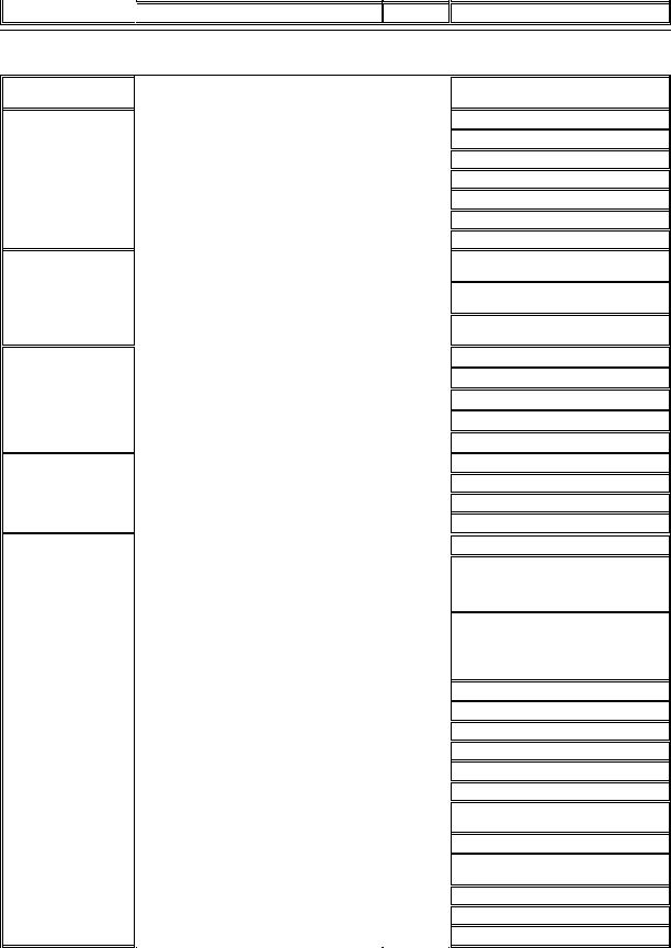
Looking at and listening to your system is important in determining the source of a problem. Look and listen for the indications described in Table 1.
If after looking and listening to your computer you have not resolved the problem, continue with the recommendations in "System Setup."
Table 1. Boot Routine Indications
Look/Listen for: |
Action |
|
|
|
|
|
|
|
An error message |
See "Messages and Codes." |
|
|
|
|
|
|
|
The monitor's power indicator |
Most monitors have a power indicator (usually on the front bezel). If the monitor's power indicator does not light |
|
|
up, see "Troubleshooting the Monitor." |
|
|
|
|
|
|
|
The power and hard-disk |
Use the power and hard-disk drive indicators to help you identify a system problem when you press the power |
|
drive indicators |
button to turn on the computer but the system does not boot. |
|
|
|
|
|
|
|
The power indicator |
Use the power indicator to help you identify a system problem when you press the power button to turn on the |
|
|
computer but the system does not boot: |
|
|
• |
A blinking yellow power indicator before power-on self-test (POST) indicates that the power supply may be |
|
|
faulty. In rare cases, the system board may be faulty. See "Getting Help" for instructions on getting |
|
|
technical assistance from Dell. |
|
• |
A solid yellow power indicator before POST indicates that a device on the system board may be faulty or |
|
|
is incorrectly installed. Be sure that the microprocessor is properly seated, remove all expansion cards, |
|
|
and then reboot. If the system does not boot, see "Getting Help" for instructions on getting technical |
|
|
assistance from Dell. |
|
• |
A solid green power indicator and a beep code during POST indicate that a dual in-line memory module |
|
|
(DIMM) may be faulty or is not properly seated. Remove all DIMMs, install only one DIMM, and then reboot. |
|
|
Repeat this procedure until you identify the faulty or improperly seated DIMM. |
|
• |
A solid green power indicator and no beep code and no video during POST indicate that the monitor or |
|
|
the integrated video controller may be faulty. See "Troubleshooting the Monitor." If the monitor is operating |
|
|
properly and is correctly connected, see "Getting Help" for instructions on getting technical assistance |
|
|
from Dell. |
|
• |
A solid green power indicator and no beep code with video during POST indicate that an integrated |
|
|
system board device may be faulty. See "Getting Help" for instructions on getting technical assistance |
|
|
from Dell. |
|
|
|
|
|
|
The keyboard indicators |
Most keyboards have one or more indicators (usually in the upper-right corner). Press the <Num Lock> key, the |
|
|
<Caps Lock> key, and the <Scroll Lock> key to toggle the keyboard indicators on and off. If the keyboard |
|
|
indicators do not light up, see "Troubleshooting the Keyboard." |
|
|
|
|
The diskette-drive access indicator
The diskette-drive access indicator should quickly flash on and off when you access data on the diskette drive. On a system running a Microsoft® Windows® operating system, you can test the drive by opening Windows Explorer and clicking the icon for drive A. If the diskette-drive access indicator does not light up, see "Troubleshooting Drives."
The hard-disk drive access indicator
The hard-disk drive access indicator should quickly flash on and off when you access data on the hard-disk drive. On a system running a Windows operating system, you can test the drive by opening Windows Explorer and clicking the icon for drive C. If the hard-disk drive access indicator does not light up, see "Troubleshooting Drives."
A series of beeps |
See "Messages and Codes." |
|
|
An unfamiliar constant scraping or grinding sound when you access a drive
The absence of a familiar sound
Make sure the sound is not caused by the application program you are running. The sound could be caused by a hardware malfunction. See "Getting Help" for instructions on getting technical assistance from Dell.
When you turn on your system, you can hear the hard-disk drive spin up, and the system tries to access the boot files from the hard-disk drive or the diskette drive. If your system boots, see "Dell Diagnostics." If your system does not boot, see "Getting Help."

System Setup
You can easily correct certain system problems by verifying the correct settings in System Setup. When you boot your system, your system checks the system configuration information and compares it with the current hardware configuration. If your system hardware configuration does not match the information recorded by System Setup, an error message may appear on your screen.
This problem can happen if you changed your system's hardware configuration and forgot to run System Setup. To correct this problem, enter System Setup, correct the setting for the corresponding System Setup program option, and reboot your system.
If after checking the settings in System Setup you have not resolved the problem, see "Dell Diagnostics."
Back to Contents Page

Back to Contents Page
Battery: Dell™ OptiPlex™ GX110 System User's Guide
Overview
Replacing the Battery
Overview
A 3.0-volt (V) CR2032 coin-cell battery installed on the system board maintains system configuration, date, and time information in a special section of memory.
The operating life of the battery can extend up to ten years. The battery may need replacing if an incorrect time or date is displayed during the boot routine along with a message such as:
Time-of-day not set - please run SETUP program
or
Invalid configuration information - please run SETUP program
or
Strike the F1 key to continue,
F2 to run the setup utility
To determine whether you need to replace the battery, reenter the time and date through System Setup and exit the program properly to save the information. Turn off your system and disconnect it from the electrical outlet for a few hours; then reconnect and turn on your system. Enter System Setup. If the date and time are not correct in System Setup, replace your battery.
You can operate your system without a battery; however, without a battery, the system configuration information is erased if the system is turned off or unplugged from the electrical outlet. In this case, you must enter System Setup and reset the configuration options.
CAUTION: There is a danger of the new battery exploding if it is incorrectly installed. Replace the battery only with the same or equivalent type recommended by the manufacturer. Discard used batteries according to the manufacturer's instructions.
Replacing the Battery
To replace the system battery, perform the following steps:
1.If you have not already done so, make a copy of your system configuration information in System Setup.
If the settings are lost while you are replacing the battery, refer to your written or printed copy of the system configuration information to restore the correct settings.
CAUTION: Before you remove the computer cover, see "Safety First — For You and Your Computer."
2.Remove the computer cover according to the instructions in "Removing and Replacing the Computer Cover."
3.Remove the battery.
See Figure 9 in "Inside Your Computer" for the location of the battery.
NOTICE: If you pry the battery out of its socket with a blunt object, be careful not to touch the system board with the object. Make certain that the object is inserted between the battery and the socket before you attempt to pry out the battery. Otherwise, you may damage the system board by prying off the socket or by breaking circuit traces on the system board.
Pry the battery out of its socket with your fingers or with a blunt, nonconductive object, such as a plastic screwdriver.
4.Install the new battery.
Orient the battery with the side labeled "+" facing up (see Figure 1). Then insert the battery into the socket, and snap it into place.
Figure 1. Replacing the System Battery
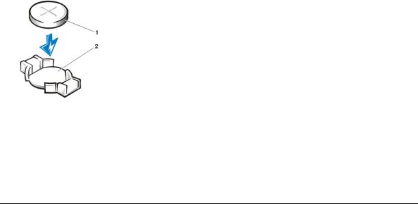
1Battery
2Battery socket
5.Replace the computer cover, reconnect your computer and peripherals to their electrical outlets, and turn them on.
6.Enter System Setup, and confirm that the battery is operating properly.
Enter the correct time and date through System Setup's System Time and System Date options. Also, use the copy you made in step 1 of the system configuration information to restore the correct settings for other System Setup options. Then exit System Setup.
7.Turn off and unplug your computer. Leave the computer turned off for at least 10 minutes.
8.After 10 minutes, plug in the computer, turn it on, and enter System Setup. If the time and date are still incorrect, see "Getting Help" for instructions on obtaining technical assistance.
Back to Contents Page
Back to Contents Page
Contacting Dell: Dell™ OptiPlex™ GX110 System User's Guide
Overview |
Europe Contact Numbers |
International Dialing Codes |
Asia and Other Regions Contact Numbers |
Americas Contact Numbers |
|
|
|
Overview
When you need to contact Dell, use the telephone numbers, codes, and electronic addresses provided in the following sections. "International Dialing Codes" provides the various codes required to make long-distance and international calls. "Americas Contact Numbers," "Europe Contact Numbers," and "Asia and Other Regions Contact Numbers" provide local telephone numbers, area codes, toll-free numbers, and e-mail addresses, if applicable, for each department or service available in various countries around the world.
If you are making a direct-dialed call to a location outside of your local telephone service area, determine which codes to use (if any) in "International Dialing Codes," in addition to the local numbers provided in the other sections.
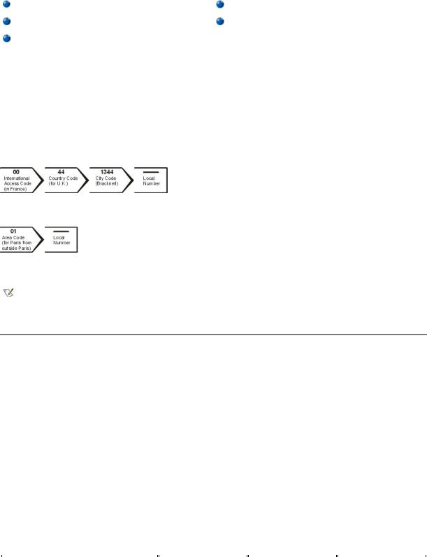
For example, to place an international call from Paris, France to Bracknell, England, dial the international access code for France followed by the country code for the U.K., the city code for Bracknell, and then the local number as shown in the following illustration:
To place a long-distance call within your own country, use area codes instead of international access codes, country codes, and city codes. For example, to call Paris, France from Montpellier, France, dial the area code plus the local number as shown in the following illustration:
The codes required depend on where you are calling from as well as the destination of your call; in addition, each country has a different dialing protocol. If you need assistance in determining which codes to use, contact a local or an international operator.
NOTES: Toll-free numbers are for use only within the country for which they are listed. Area codes are most often used to call long distance within your own country (not internationally)—in other words, when your call originates in the same country you are calling.
Have your Express Service Code ready when you call. The code helps Dell's automated-support telephone system direct your call more efficiently.
International Dialing Codes
Click a listed country to obtain the appropriate contact numbers.
|
International Access |
|
|
Country (City) |
Code |
Country Code |
City Code |
|
|
|
|
|
|
|
|
Australia (Sydney) |
0011 |
61 |
2 |
|
|
|
|
|
|
|
|
Austria (Vienna) |
900 |
43 |
1 |
|
|
|
|
|
|
|
|
Belgium (Brussels) |
00 |
32 |
2 |
|
|
|
|
|
|
|
|
Brazil |
0021 |
55 |
51 |
|
|
|
|
|
|
|
|
Brunei |
— |
673 |
— |
|
|
|
|
|
|
|
|
Canada (North York, Ontario) |
011 |
— |
Not required |
|
|
|
|
|
|
|
|
Chile (Santiago) |
— |
56 |
2 |
|
|
|
|
China (Xiamen) |
— |
86 |
592 |
|
|
|
|
|
|
|
|
Czech Republic (Prague) |
00 |
420 |
2 |
|
|
|
|
|
|
|
|
Denmark (Horsholm) |
00 |
45 |
Not required |
|
|
|
|
|
|
|
|
Finland (Helsinki) |
990 |
358 |
9 |
|
|
|
|
|
|
|
|
France (Paris) (Montpellier) |
00 |
33 |
(1) (4) |
|
|
|
|
|
|
|
|
Germany (Langen) |
00 |
49 |
6103 |
|
|
|
|
Hong Kong |
001 |
852 |
Not required |
|
|
|
|
|
|
|
|
Ireland (Cherrywood) |
16 |
353 |
1 |
|
|
|
|
|
|
|
|
Italy (Milan) |
00 |
39 |
02 |
|
|
|
|
|
|
|
|
Japan (Kawasaki) |
001 |
81 |
44 |
|
|
|
|
|
|
|
|
Korea (Seoul) |
001 |
82 |
2 |
|
|
|
|
|
|
|
|
Luxembourg |
00 |
352 |
— |
|
|
|
|
|
|
|
|
Macau |
— |
853 |
Not required |
|
|
|
|
|
|
|
|
Malaysia (Penang) |
00 |
60 |
4 |
|
|
|
|
|
|
|
|
Mexico (Colonia Granada) |
95 |
52 |
5 |
|
|
|
|
|
|
|
|
Netherlands (Amsterdam) |
00 |
31 |
20 |
|
|
|
|
|
|
|
|
New Zealand |
00 |
64 |
— |
|
|
|
|
|
|
|
|
Norway (Lysaker) |
00 |
47 |
Not required |
|
|
|
|
Poland (Warsaw) |
011 |
48 |
22 |
|
|
|
|
|
|
|
|
Portugal |
00 |
35 |
— |
|
|
|
|
|
|
|
|
Singapore (Singapore) |
005 |
65 |
Not required |
|
|
|
|
|
|
|
|
South Africa (Johannesburg) |
09/091 |
27 |
11 |
|
|
|
|
|
|
|
|
Spain (Madrid) |
00 |
34 |
91 |
|
|
|
|
|
|
|
|
Sweden (Upplands Vasby) |
00 |
46 |
8 |
|
|
|
|
|
|
|
|
Switzerland (Geneva) |
00 |
41 |
22 |
|
|
|
|
|
|
|
|
Taiwan |
002 |
886 |
— |
|
|
|
|
|
|
|
|
Thailand |
001 |
66 |
— |
|
|
|
|
|
|
|
|
U.K. (Bracknell) |
010 |
44 |
1344 |
|
|
|
|
|
|
|
|
U.S.A. (Austin, Texas) |
011 |
1 |
Not required |
|
|
|
|
|
|
|
|
|
|
|
|
Americas Contact Numbers
|
|
|
Local Number or |
Country (City) |
Department Name or Service |
Area Code |
Toll-Free Number |
|
|
|
|
|
|
|
|
Brazil |
Customer Support, Technical Support |
|
toll free: 0800 90 3355 |
|
|
|
|
|
|
|
|
|
Sales |
|
toll free: 0800 90 3366 |
|
|
|
|
|
|
|
|
|
Web site: http://www.dell.com/br |
|
|
|
|
|
|
|
|
|
|
Canada |
Automated Order-Status System |
|
toll free: 1-800-433-9014 |
(North York, Ontario) |
|
|
|
|
|
|
|
|
AutoTech (Automated technical support) |
|
toll free: 1-800-247-9362 |
|
|
|
|
|
|
|
|
|
Customer Care (From outside Toronto) |
|
toll free: 1-800-387-5759 |
|
|
|
|
|
|
|
|
|
Customer Care (From within Toronto) |
416 |
758-2400 |
|
|
|
|
|
|
|
|
|
Customer Technical Support |
|
toll free: 1-800-847-4096 |
|
|
|
|
|
|
|
|
|
Sales (Direct Sales—from outside Toronto) |
|
toll free: 1-800-387-5752 |
|
|
|
|
|
|
|
|
|
Sales (Direct Sales—from within Toronto) |
416 |
758-2200 |
|
|
|
|
|
|
|
|
|
Sales (Federal government, education, and medical) |
|
toll free: 1-800-567-7542 |
|
|
|
|
|
|
|
|
|
Sales (Major Accounts) |
|
toll free: 1-800-387-5755 |
|
|
|
|
|
|
|
|
|
TechFax |
|
toll free: 1-800-950-1329 |
|
|
|
|
|
|
|
|
Chile |
Sales, Customer Support, and Technical Support |
|
toll free: 1230-020-4823 |
(Santiago) |
|
|
|
NOTE: Customers in |
|
|
|
Chile call the U.S.A. for sales, customer, and technical assistance
Latin America |
Customer Technical Support (Austin, Texas, U.S.A.) |
512 |
728-4093 |
NOTE: Customers in Latin |
|
|
|
|
|
|
|
Customer Service (Austin, Texas, U.S.A.) |
512 |
728-3619 |
|
America call the U.S.A. for |
|
|
|
|
|
|
|
sales, customer, and |
Fax (Technical Support and Customer Service) |
512 |
728-3883 |
technical assistance. |
(Austin, Texas, U.S.A.) |
|
|
|
|
|
|
|
|
|
|
|
Sales (Austin, Texas, U.S.A.) |
512 |
728-4397 |
|
|
|
|
|
|
|
|
|
SalesFax (Austin, Texas, U.S.A.) |
512 |
728-4600 |
|
|
|
728-3772 |
|
|
|
|
Mexico
NOTE: Customers in Mexico call the U.S.A. for access to the Automated Order-Status System and AutoTech.
U.S.A.
(Austin, Texas)
Automated Order-Status System (Austin, Texas, U.S.A.) |
512 |
728-0685 |
|
|
|
|
|
|
AutoTech (Automated technical support) (Austin, Texas, |
512 |
728-0686 |
U.S.A.) |
|
|
|
|
|
|
|
|
Customer Technical Support |
525 |
228-7870 |
|
|
|
|
|
|
Sales |
525 |
228-7811 |
|
|
toll free: 91-800-900-37 |
|
|
toll free: 91-800-904-49 |
|
|
|
|
|
|
Customer Service |
525 |
228-7878 |
|
|
|
|
|
|
Main |
525 |
228-7800 |
|
|
|
|
|
|
Automated Order-Status System |
|
toll free: 1-800-433-9014 |
|
|
|
|
|
|
AutoTech (for portable and desktop computers) |
|
toll free: 1-800-247-9362 |
|
|
|
Dell Home and Small Business Group (for portable and desktop computers):
Customer Technical Support (Return Material
Authorization Numbers)
Customer Technical Support
(Home sales purchased via http://www.dell.com)
Customer Service
(Credit Return Authorization Numbers)
toll free: 1-800-624-9896
toll free: 1-877-576-3355
toll free: 1-800-624-9897
National Accounts (systems purchased by established Dell national accounts [have your account number handy], medical institutions, or value-added resellers [VARs]):
Customer Service and Technical Support (Return |
|
toll free: 1-800-822-8965 |
Material Authorization Numbers) |
|
|
|
|
|
Public Americas International (systems purchased by governmental agencies [local, state, or federal] or educational institutions):
Customer Service and Technical Support (Return |
|
toll free: 1-800-234-1490 |
Material Authorization Numbers) |
|
|
|
|
|
|
|
|
Dell Sales |
|
toll free: 1-800-289-3355 |
|
|
toll free: 1-800-879-3355 |
|
|
|
|
|
|
Spare Parts Sales |
|
toll free: 1-800-357-3355 |
|
|
|
|
|
|
DellWare™ |
|
toll free: 1-800-753-7201 |
|
|
|
|
|
|
Desktop and Portable Fee-Based Technical Support |
|
toll free: 1-800-433-9005 |
|
|
|
|
|
|
Server Fee-Based Technical Support |
|
toll free: 1-800-967-0765 |
|
|
|
|
|
|
Sales (Catalogs) |
|
toll free: 1-800-426-5150 |
|
|
|
|
|
|
Fax |
|
toll free: 1-800-727-8320 |
|
|
|
|
|
|
TechFax |
|
toll free: 1-800-950-1329 |
|
|
|
|
|
|
Dell Services for the Deaf, Hard-of-Hearing, or Speech- |
|
toll free: 1-877-DELLTTY |
Impaired |
|
(1-877-335-5889) |
|
|
|
|
|
|
Switchboard |
512 |
338-4400 |
|
|
|

Europe Contact Numbers
Country (City)
Austria
(Vienna)
NOTE: Customers in Austria call Langen, Germany for Technical Support and Customer Care.
Belgium (Brussels)
Czech Republic
(Prague)
Denmark
(Horsholm)
NOTE: Customers in Denmark call Sweden for fax technical support.
Finland
(Helsinki)
Department Name or Service
Switchboard
Home/Small Business Sales
Home/Small Business Sales Fax
Home/Small Business Customer Care
Preferred Accounts/Corporate Customer Care
Home/Small Business Technical Support
Preferred Accounts/Corporate Technical Support
Web site: http://support.euro.dell.com
E-mail: tech_support_central_europe@dell.com
Technical Support
Customer Care
Home/Small Business Sales
Corporate Sales
Fax
Switchboard
Web site: http://support.euro.dell.com
E-mail: tech_be@dell.com
Technical Support
Customer Care
Fax
TechFax
Switchboard
Web site: http://support.euro.dell.com
E-mail: czech_dell@dell.com
Technical Support
Relational Customer Care
Home/Small Business Customer Care
Switchboard
Fax Technical Support (Upplands Vasby, Sweden)
Fax Switchboard
Web site: http://support.euro.dell.com
E-mail: den_support@dell.com
E-mail Support for Servers:
Nordic_server_support@dell.com
Technical Support
Technical Support Fax
Relational Customer Care
Home/Small Business Customer Care
Fax
Switchboard
Web site: http://support.euro.dell.com
E-mail: fin_support@dell.com
Area Code
01
01
01
01
01
02
02
02
02
02
02
02
02
02
02
46
09
09
09
09
09
09
Local Number or Toll-Free Number
491 040
795676-02
795676-05
795676-03
0660-8056
795676-04
0660-8779
481 92 88
481 91 19
toll free: 0800 16884
481 91 00
481 92 99
481 91 00
22 83 27 27
22 83 27 11
22 83 27 14
22 83 27 28
22 83 27 11
45170182
45170184
32875505
45170100
859005594
45170117
253 313 60
253 313 81
253 313 38
693 791 94
253 313 99
253 313 00
France |
Home and Small Business |
|
|
|
(Paris/Montpellier) |
|
|
|
|
|
|
|
||
Technical Support |
0825 |
387 270 |
||
|
||||
|
|
|
|
|
|
|
|
|
|
|
Customer Care |
0825 |
823 833 |
|
|
|
|
|
|
|
|
|
|
|
|
Fax |
0825 |
004 701 |
|
|
|
|
|
|
|
|
|
|
|
|
Switchboard |
0825 |
004 700 |
|
|
|
|
|
|
|
|
|
|
|
|
Switchboard (Alternative) |
04 |
99 75 40 00 |
|
|
|
|
|
|
|
|
|
|
|
|
Sales |
0825 |
004 700 |
|
|
|
|
|
|
|
|
|
|
|
|
Web site: http://support.euro.dell.com |
|
|
|
|
|
|
|
|
|
|
|
|
|
|
E-mail: web_fr_tech@dell.com |
|
|
|
|
|
|
|
|
|
|
|
|
|
|
Corporate |
|
|
|
|
|
|
|
|
|
|
|
|
|
|
Technical Support |
0825 |
004 719 |
|
|
|
|
|
|
|
|
|
|
|
|
Customer Care |
0825 |
338 339 |
|
|
|
|
|
|
|
|
|
|
|
|
Fax |
01 |
55 94 71 01 |
|
|
|
|
|
|
|
|
|
|
|
|
Switchboard |
01 |
55 94 71 00 |
|
|
|
|
|
|
|
|
|
|
|
|
Sales |
01 |
55 94 71 00 |
|
|
|
|
|
|
|
Web site: http://support.euro.dell.com |
|
|
|
|
|
|
|
|
|
|
|
|
|
|
E-mail: web_fr_tech@dell.com |
|
|
|
|
|
|
|
|
|
|
|
|
|
Germany |
Technical Support |
06103 |
766-7200 |
|
(Langen) |
|
|
|
|
|
|
|
||
Home/Small Business Customer Care |
|
0180-5-224400 |
||
|
|
|||
|
|
|
|
|
|
|
|
|
|
|
Global Segment Customer Care |
06103 |
766-9570 |
|
|
|
|
|
|
|
|
|
|
|
|
Preferred Accounts Customer Care |
06103 |
766-9420 |
|
|
|
|
|
|
|
|
|
|
|
|
Large Accounts Customer Care |
06103 |
766-9560 |
|
|
|
|
|
|
|
|
|
|
|
|
Public Accounts Customer Care |
06103 |
766-9555 |
|
|
|
|
|
|
|
|
|
|
|
|
Switchboard |
06103 |
766-7000 |
|
|
|
|
|
|
|
|
|
|
|
|
Web site: http://support.euro.dell.com |
|
|
|
|
|
|
|
|
|
|
|
|
|
|
E-mail: |
|
|
|
|
tech_support_central_europe@dell.com |
|
|
|
|
|
|
|
|
|
|
|
|
|
Ireland |
Technical Support |
|
0870 908 0800 |
|
(Cherrywood) |
|
|
|
|
|
|
|
||
Home User Customer Care |
01 |
204 4095 |
||
|
||||
|
|
|
|
|
|
|
|
|
|
|
Small Business Customer Care |
01 |
204 4026 |
|
|
|
|
|
|
|
|
|
|
|
|
Corporate Customer Care |
01 |
204 4003 |
|
|
|
|
|
|
|
|
|
|
|
|
Sales |
01 |
286 0500 |
|
|
|
|
|
|
|
|
|
|
|
|
SalesFax |
01 |
204 0144 |
|
|
|
|
|
|
|
|
|
|
|
|
Fax |
|
0870 907 5590 |
|
|
|
|
|
|
|
|
|
|
|
|
Switchboard |
01 |
286 0500 |
|
|
|
|
|
|
|
|
|
|
|
|
Web site: http://support.euro.dell.com |
|
|
|
|
|
|
|
|
|
|
|
|
|
|
E-mail: dell_direct_support@dell.com |
|
|
|
|
|
|
|
|
|
|
|
|
|
Italy |
Home and Small Business |
|
|
|
(Milan) |
|
|
|
|
|
|
|
||
Technical Support |
02 |
577 826 90 |
||
|
||||
|
|
|
|
|
|
|
|
|
|
|
Customer Care |
02 |
696 821 14 |
|
|
|
|
|
|
|
Fax |
02 |
696 821 13 |
|
|
|
|
|
|
|
|
|
|
|
|
Switchboard |
02 |
696 821 11 |
|
|
|
|
|
|
|
|
|
|
|
|
Web site: http://support.euro.dell.com |
|
|
|
|
|
|
|
|
|
|
|
|
|
|
E-mail: web_it_tech@dell.com |
|
|
|
|
|
|
|
|
|
|
|
|
|
|
Corporate |
|
|
|
|
|
|
|
|
|
|
|
|
|
|
Technical Support |
02 |
577 826 90 |
|
|
|
|
|
|
|
|
|
|
|
|
Customer Care |
02 |
577 825 55 |
|
|
|
|
|
|
|
|
|
|

|
Fax |
|
|
|
|
|
Switchboard |
|
|
|
|
|
|
|
|
Web site: http://support.euro.dell.com |
|
|
|
|
|
|
|
|
E-mail: web_it_tech@dell.com |
|
|
|
|
|
|
|
Luxembourg |
Technical Support (Brussels, Belgium) |
|
|
|
|
|
|
|
NOTE: Customers in |
Home/Small Business Sales (Brussels, Belgium) |
|
|
||
|
||
Luxembourg call Belgium |
Corporate Sales (Brussels, Belgium) |
|
for sales, customer, and |
|
|
|
||
Customer Care (Brussels, Belgium) |
||
technical assistance. |
||
|
||
|
|
|
|
Switchboard (Brussels, Belgium) |
|
|
|
|
|
|
|
|
Fax (Brussels, Belgium) |
|
|
|
|
|
|
|
|
Web site: http://support.euro.dell.com |
|
|
|
|
|
|
|
|
E-mail: tech_be@dell.com |
|
|
|
|
|
|
|
Netherlands |
Technical Support |
|
(Amsterdam) |
|
|
|
||
Customer Care |
||
|
||
|
|
|
|
|
|
|
Home/Small Business Sales |
|
|
|
|
|
Home/Small Business Sales Fax |
|
|
|
|
|
|
|
|
Corporate Sales |
|
|
|
|
|
|
|
|
Corporate Sales Fax |
|
|
|
|
|
|
|
|
Fax |
|
|
|
|
|
|
|
|
Switchboard |
|
|
|
|
|
|
|
|
Web site: http://support.euro.dell.com |
|
|
|
|
|
|
|
|
E-mail: tech_nl@dell.com |
|
|
|
|
|
|
|
Norway |
Technical Support |
|
(Lysaker) |
|
|
|
||
Relational Customer Care |
||
|
||
NOTE: Customers in |
|
|
|
||
Home/Small Business Customer Care |
||
Norway call Sweden for fax |
|
|
|
||
Switchboard |
||
technical support. |
||
|
||
|
|
|
|
Fax Technical Support (Upplands Vasby, Sweden) |
|
|
|
|
|
|
|
|
Fax Switchboard |
|
|
|
|
|
|
|
|
Web site: http://support.euro.dell.com |
|
|
|
|
|
|
|
|
E-mail: nor_support@dell.com |
|
|
E-mail Support for Servers: |
|
|
Nordic_server_support@dell.com |
|
|
|
|
|
|
|
Poland |
Technical Support |
|
(Warsaw) |
|
|
|
||
Customer Care |
||
|
||
|
|
|
|
|
|
|
Sales |
|
|
|
|
|
|
|
|
Switchboard |
|
|
|
|
|
|
|
|
Fax |
|
|
|
|
|
|
|
|
Web site: http://support.euro.dell.com |
|
|
|
|
|
|
|
|
E-mail: pl_support@dell.com |
|
|
|
|
|
|
|
Portugal |
Technical Support |
|
|
|
|
|
|
|
|
Customer Care |
|
|
|
|
|
|
|
|
Sales |
|
|
|
|
|
|
|
|
Switchboard |
|
|
|
|
|
|
|
|
Fax |
|
|
|
|
|
|
|
|
E-mail es_support@dell.com |
02
02
02
02
02
02
02
020
020
020
020
020
020
020
00
22
22
22
22
22
35
34
35
575 035 30
577 821
481 92 88
toll free: 080016884
481 91 00
481 91 19
481 91 00
481 92 99
581 8838
581 8740
toll free: 0800-0663
682 7171
581 8818
686 8003
686 8003
581 8818
671 16882
671 17514
231 62298
671 16800
08 590 05 594
671 16865
57 95 700
57 95 999
57 95 999
57 95 999
57 95 998
800 834 077
800 300 415 or 800 834 075
800 300 410 or 800 300 411 or 800 300 412
or 351 214 220 710
917 229 200
121 424 01 12

|
|
|
|
|
Spain |
Home and Small Business |
|
|
|
(Madrid) |
|
|
|
|
|
|
|
||
Technical Support |
|
902 100 130 |
||
|
|
|||
|
|
|
|
|
|
|
|
|
|
|
Customer Care |
|
902 118 540 |
|
|
|
|
|
|
|
|
|
|
|
|
Switchboard |
|
902 118 541 |
|
|
|
|
|
|
|
|
|
|
|
|
Fax |
|
902 118 539 |
|
|
|
|
|
|
|
|
|
|
|
|
Web site: http://support.euro.dell.com |
|
|
|
|
|
|
|
|
|
|
|
|
|
|
E-mail: web_esp_tech@dell.com |
|
|
|
|
|
|
|
|
|
|
|
|
|
|
Corporate |
|
|
|
|
|
|
|
|
|
|
|
|
|
|
Technical Support |
|
902 100 130 |
|
|
|
|
|
|
|
|
|
|
|
|
Customer Care |
|
902 118 546 |
|
|
|
|
|
|
|
|
|
|
|
|
Switchboard |
91 |
722 92 00 |
|
|
|
|
|
|
|
|
|
|
|
|
Fax |
91 |
722 95 83 |
|
|
|
|
|
|
|
|
|
|
|
|
Web site: http://support.euro.dell.com |
|
|
|
|
|
|
|
|
|
|
|
|
|
|
E-mail: web_esp_tech@dell.com |
|
|
|
|
|
|
|
|
|
|
|
|
|
Sweden |
Technical Support |
08 |
590 05 199 |
|
(Upplands Vasby) |
|
|
|
|
Relational Customer Care |
08 |
590 05 642 |
||
|
||||
|
|
|
|
|
|
|
|
|
|
|
Home/Small Business Customer Care |
08 |
587 70 527 |
|
|
|
|
|
|
|
|
|
|
|
|
Fax Technical Support |
08 |
590 05 594 |
|
|
|
|
|
|
|
|
|
|
|
|
Sales |
08 |
590 05 185 |
|
|
|
|
|
|
|
|
|
|
|
|
Web site: http://support.euro.dell.com |
|
|
|
|
|
|
|
|
|
|
|
|
|
|
E-mail: swe_support@dell.com |
|
|
|
|
E-mail Support for Latitude™ and Inspiron™: Swe- |
|
|
|
|
nbk_kats@dell.com |
|
|
|
|
E-mail Support for OptiPlex™ : |
|
|
|
|
Swe_kats@dell.com |
|
|
|
|
E-mail Support for Servers: |
|
|
|
|
Nordic_server_support@dell.com |
|
|
|
|
|
|
|
|
|
|
|
|
|
Switzerland |
Technical Support (Home and Small Business) |
|
0844 811 411 |
|
(Geneva) |
|
|
|
|
|
|
|
||
Technical Support (Corporate) |
|
0844 822 844 |
||
|
|
|||
|
|
|
|
|
|
|
|
|
|
|
Customer Care (Home and Small Business) |
|
0848 802 202 |
|
|
|
|
|
|
|
|
|
|
|
|
Customer Service (Corporate) |
|
0848 821 721 |
|
|
|
|
|
|
|
|
|
|
|
|
Switchboard |
022 |
799 01 01 |
|
|
|
|
|
|
|
|
|
|
|
|
Fax |
022 |
799 01 90 |
|
|
|
|
|
|
|
|
|
|
|
|
Web site: http://support.euro.dell.com |
|
|
|
|
|
|
|
|
|
|
|
|
|
|
E-mail: swisstech@dell.com |
|
|
|
|
|
|
|
|
|
|
|
|
|
U.K. |
Technical Support (Corporate/Preferred |
0870 |
908 0500 |
|
(Bracknell) |
Accounts/PAD [1000+ employees]) |
|||
|
|
|||
|
|
|
|
|
|
Technical Support (Direct/PAD and General) |
0870 |
908 0800 |
|
|
|
|
|
|
|
|
|
|
|
|
Global Accounts Customer Care |
01344 |
723186 |
|
|
|
|
|
|
|
|
|
|
|
|
Corporate Customer Care |
0870 |
908 0500 |
|
|
|
|
|
|
|
|
|
|
|
|
Preferred Accounts (500-5000 employees) |
01344 |
723 196 |
|
|
Customer Care |
|||
|
|
|
||
|
|
|
|
|
|
|
|
|
|
|
Central Government Customer Care |
01344 |
723 193 |
|
|
|
|
|
|
|
Local Government Customer Care |
01344 |
723 194 |
|
|
|
|
|
|
|
|
|
|
|
|
Home/Small Business Sales |
0870 |
907 4000 |
|
|
|
|
|
|
|
|
|
|
|
|
Home/Small Business Customer Care |
0870 |
906 0010 |
|
|
|
|
|
|
|
|
|
|
|
|
Corporate/Public Sector Sales |
01344 |
860 456 |
|
|
|
|
|
|
|
|
|
|
|
|
Web site: http://support.euro.dell.com |
|
|
|
|
|
|
|

 E-mail: dell_direct_support@dell.com
Asia and Other Regions Contact Numbers
Country (City)
Australia
(Sydney)
Brunei
NOTE: Customers in Brunei call Malaysia for customer assistance.
China
(Xiamen)
Hong Kong
NOTE: Customers in Hong Kong call Malaysia for customer assistance.
Japan
(Kawasaki)
Department Name or Service |
Area Code |
|
|
|
|
Home and Small Business |
|
|
|
|
|
Government and Business |
|
|
|
|
|
Preferred Accounts Division (PAD) |
|
|
|
|
|
Customer Care |
|
|
|
|
|
Corporate Sales |
|
|
|
|
|
Transaction Sales |
|
|
|
|
|
Fax |
|
|
|
|
|
Customer Technical Support |
|
(Penang, Malaysia) |
|
|
|
|
|
Customer Service |
|
(Penang, Malaysia) |
|
|
|
Transaction Sales |
|
(Penang, Malaysia) |
|
|
|
|
|
Technical Support |
|
|
|
|
|
Customer Experience |
|
|
|
|
|
Home and Small Business |
|
|
|
|
|
Preferred Accounts Division |
|
|
|
|
|
Large Corporate Accounts |
|
|
|
|
|
Technical Support |
|
|
|
Customer Service (Penang, Malaysia) |
|
|
|
|
|
Transaction Sales |
|
|
|
|
|
Corporate Sales |
|
|
|
|
|
Technical Support (Server) |
|
|
|
|
|
Technical Support (Dimension™ and Inspiron) |
|
Technical Support Outside of Japan (Dimension |
|
and Inspiron) |
81-44 |
|
|
|
|
Technical Support (Dell Precision™, OptiPlex, and |
|
Latitude) |
|
Technical Support Outside of Japan (Dell Precision, |
81-44 |
|
|
OptiPlex, and Latitude) |
|
|
|
|
|
Customer Care |
044 |
|
|
|
|
24-Hour Automated Order Status Service |
044 |
|
|
|
|
Home and Small Business Group Sales |
044 |
|
|
|
|
Individual User Sales |
044 |
|
|
|
|
Business Sales Division (up to 400 employees) |
044 |
|
|
|
|
Government, Educational, and Medical Sales |
044 |
|
|
|
|
Preferred Accounts Division Sales (over 400 |
044 |
employees) |
|
|
|
|
|
Dell Global Japan |
044 |
|
|
|
|
Large Corporate Accounts Sales (over 3500 |
044 |
employees) |
|
|
|
Faxbox Service |
044 |
|
|
|
|
Switchboard |
044 |
|
|
|
|
Web site: http://support.jp.dell.com |
|
|
|
|
|
Local Number or Toll-Free Number
1-300-65-55-33
toll free: 1-800-633-559
toll free: 1-800-060-889
toll free: 1-800-819-339
toll free: 1-800-808-385
toll free: 1-800-808-312
toll free: 1-800-818-341
633 4966
633 4949
633 4955
toll free: 800 858 2437
toll free: 800 858 2060
toll free: 800 858 2222
toll free: 800 858 2062
toll free: 800 858 2999
toll free: 800 96 4107
633 4949
toll free: 800 96 4109
toll free: 800 96 4108
toll free: 0120-1984-35
toll free: 0120-1982-26
520-1435
toll free: 0120-1984-33
556-3894
556-4240
556-3801
556-3344
556-3344
556-3344
556-1469
556-3433
556-3469
556-3430
556-3490
556-4300

Korea
(Seoul)
Macau
NOTE: Customers in Macau call Malaysia for customer assistance.
Malaysia
(Penang)
New Zealand
Singapore
(Singapore)
NOTE: Customers in Singapore call Malaysia for customer assistance.
South Africa
(Johannesburg)
Southeast Asian/Pacific Countries
(excluding Australia, Brunei, China, Hong Kong, Japan, Korea, Macau, Malaysia, New Zealand, Singapore, Taiwan, and Thailand—refer to individual listings for these countries)
Taiwan
Thailand
NOTE: Customers in Thailand call Malaysia for customer assistance.
Technical Support |
|
toll free: 080-200-3800 |
|
|
|
Sales |
|
toll free: 080-200-3777 |
|
|
|
Customer Service (Penang, Malaysia) |
|
604-633-4949 |
|
|
|
|
|
|
Customer Service (Seoul, Korea) |
|
2194-6220 |
|
|
|
|
|
|
Fax |
|
2194-6202 |
|
|
|
|
|
|
Switchboard |
|
2194-6000 |
|
|
|
|
|
|
Technical Support |
|
toll free: 0800 582 |
|
|
|
|
|
|
Customer Service (Penang, Malaysia) |
|
633 4949 |
|
|
|
|
|
|
Transaction Sales |
|
toll free: 0800 581 |
|
|
|
|
|
|
Technical Support |
|
toll free: 1 800 888 298 |
|
|
|
|
|
|
Customer Service |
04 |
633 4949 |
|
|
|
|
|
|
Transaction Sales |
|
toll free: 1 800 888 202 |
|
|
|
|
|
|
Corporate Sales |
|
toll free: 1 800 888 213 |
|
|
|
|
|
|
Home and Small Business |
|
0800 446 255 |
|
|
|
|
|
|
Government and Business |
|
0800 444 617 |
|
|
|
|
|
|
Sales |
|
0800 441 567 |
|
|
|
|
|
|
Fax |
|
0800 441 566 |
|
|
|
|
|
|
Technical Support |
|
toll free: 800 6011 051 |
|
|
|
|
|
|
Customer Service (Penang, Malaysia) |
04 |
633 4949 |
|
|
|
|
|
|
Transaction Sales |
|
toll free: 800 6011 054 |
|
|
|
|
|
|
Corporate Sales |
|
toll free: 800 6011 053 |
|
|
|
|
|
|
Technical Support |
011 |
709 7710 |
|
|
|
|
|
|
Customer Care |
011 |
709 7707 |
|
|
|
|
|
|
Sales |
011 |
709 7700 |
|
|
|
|
|
|
Fax |
011 |
706 0495 |
|
|
|
|
|
|
Switchboard |
011 |
709 7700 |
|
|
|
|
|
|
Web site: http://support.euro.dell.com |
|
|
|
|
|
|
|
|
E-mail: dell_za_support@dell.com |
|
|
|
|
|
|
|
|
Customer Technical Support, Customer Service, |
|
60 4 633-4810 |
and Sales (Penang, Malaysia) |
|
|
|
|
|
Technical Support |
|
toll free: 0080 60 1225 |
|
|
|
|
|
|
Technical Support (Servers) |
|
toll free: 0080 60 1256 |
|
|
|
|
|
|
Customer Service (Penang, Malaysia) |
|
633 4949 |
|
|
|
Transaction Sales |
|
toll free: |
|
|
0080 651 228/0800 33 556 |
|
|
|
|
|
|
Corporate Sales |
|
toll free: |
|
|
0080 651 227/0800 33 555 |
|
|
|
|
|
|
Technical Support |
|
toll free: 088 006 007 |
|
|
|
|
|
|
Customer Service (Penang, Malaysia) |
|
633 4949 |
|
|
|
|
|
|
Sales |
|
toll free: 088 006 009 |
|
|
|
Back to Contents Page

Back to Contents Page
Dell™ Diagnostics: Dell OptiPlex™ GX110 System User's Guide
Overview |
Starting the Dell Diagnostics |
Features of the Dell Diagnostics |
Dell Diagnostics Main Screen Overview |
When to Use the Dell Diagnostics |
Confirming the System Configuration Information |
Before You Start Testing |
How to Use Dell Diagnostics |
|
|
Overview
Unlike many diagnostic programs, the Dell Diagnostics helps you check your computer's hardware without any additional equipment and without destroying any data. By using the diagnostics, you can have confidence in your computer system's operation. If you find a problem you cannot solve by yourself, the diagnostic tests can provide you with important information you will need when talking to Dell's service and support personnel.
NOTICE: Use the Dell Diagnostics only to test your Dell computer system. Using this program with other computers may cause incorrect computer responses or result in error messages.
Features of the Dell Diagnostics
The Dell Diagnostics provides a series of menus and options from which you choose particular test groups or subtests. You control the sequence in which the tests are run. The diagnostic test groups or subtests have the following helpful features:
•Options that let you run tests individually or collectively
•An option that allows you to choose the number of times a test group or subtest is repeated
•The ability to display or print test results or to save them in a file
•Options to temporarily suspend testing if an error is detected or to terminate testing when an adjustable error limit is reached
•A menu category called Devices that briefly describes each test and its parameters
•A menu category called Config that describes the configuration of the devices in the selected device group
•Status messages that inform you whether test groups or subtests were completed successfully
•Error messages that appear if any problems are detected
When to Use the Dell Diagnostics
Whenever a major component or device in your computer system does not function properly, you may have a component failure. As long as the microprocessor and the input and output components of your computer system (the monitor, keyboard, and diskette drive) are working, you can use the Dell Diagnostics. If you are experienced with computers and know what component(s) you need to test, simply select the appropriate diagnostic test group(s) or subtest(s). If you are unsure about how to begin diagnosing a problem, read the rest of this section.
Before You Start Testing
Turn on your printer if one is attached, and make sure it is online. Enter System Setup, confirm your computer's system configuration information, and enable all its components and devices, such as ports.
See "Using System Setup" for instructions on entering and using the program.
Starting the Dell Diagnostics
After you complete the preliminary instructions outlined in the previous section, perform the following steps to start the diagnostics:
1. Turn off your system.
2.Insert the Dell Diagnostics media (for example, a diskette or CD) into the appropriate drive.
3.Turn on your system.
When you start the diagnostics, the Dell logo screen appears, followed by a message telling you that the diagnostics is loading.
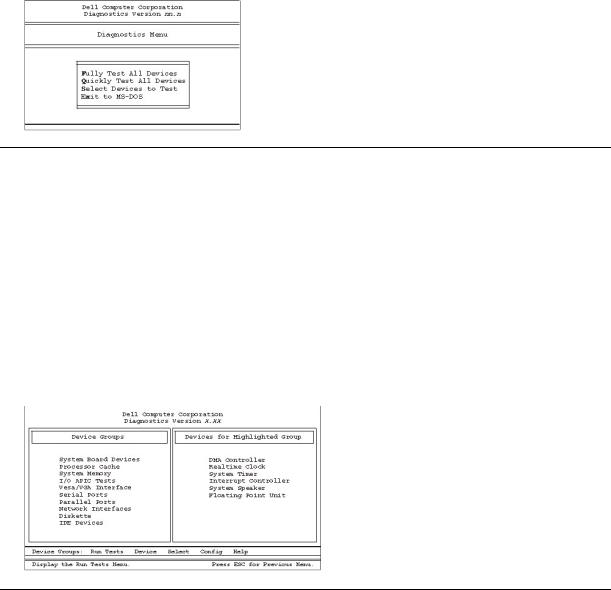
After the diagnostics loads, the Diagnostics Menu appears (see Figure 1). The menu allows you to run all or specific diagnostic tests or to exit to the MS-DOS® prompt.
For a quick check of your system, select the Quickly Test All Devices option. This option runs only the subtests that do not require user interaction and that do not take a long time to run. Dell recommends that you choose this option first to identify the source of the problem quickly. For a thorough check of your system, select the Fully Test All Devices option. To check a particular area of your system, select the Select Devices to Test option.
To select an option from this menu, highlight the option and press <Enter>, or press the key that corresponds to the highlighted letter in the option you choose.
Figure 1. Diagnostics Menu
Dell Diagnostics Main Screen Overview
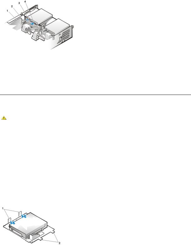
When you select Select Devices to Test from the Diagnostics Menu, the main screen of the diagnostics appears (see Figure 2). The main screen lists the diagnostic test device groups, lists the devices of the selected device group, and allows you to select categories from a menu. From this screen, you can access the main screens.
Information on the main screen of the diagnostics is presented in the following areas:
•Two lines at the top of the screen identify the version number of the Dell Diagnostics.
•On the left side of the screen, the Device Groups area lists the diagnostic test groups in the order they will run if you select All from the Run Tests menu category. Press the upor down-arrow key to highlight a test device group.
•On the right side of the screen, the Devices for Highlighted Group area lists the computer's currently detected hardware and some of the relevant settings.
•Two lines at the bottom of the screen make up the menu area. The first line lists the categories you can select; press the leftor right-arrow key to highlight a menu category. The second line gives information about the category currently highlighted.
Figure 2. Dell Diagnostics Main Screen
Confirming the System Configuration Information
When you boot your system from your diagnostics diskette, the diagnostics checks your system configuration information and displays it in the

Device Groups area on the main screen.
The following sources supply this configuration information for the diagnostics:
•The system configuration information settings (stored in nonvolatile random-access memory [NVRAM]) that you selected while using System Setup
•Identification tests of the microprocessor, the video controller, the keyboard controller, and other key components
•Basic input/output system (BIOS) configuration information temporarily saved in RAM
Do not be concerned if the Device Groups area does not list the names of all the components or devices you know are part of your computer system. For example, you may not see a printer listed, although you know one is attached to your computer. Instead, the printer is listed as a parallel port. The computer recognizes the parallel port as LPT1, which is an address that tells the computer where to send outgoing information and where to look for incoming information. Because your printer is a parallel communications device, the computer recognizes the printer by its LPT1 address and identifies it as a parallel port. You can test your printer connection in the Parallel Ports tests.
How to Use Dell Diagnostics
Six comprehensive, menu-driven, online help categories provide instructions on how to use the program and explain each menu item, test group, subtest, and test result. To enter the Help menu, perform the following steps:
1.Highlight Select Devices to Test in the Diagnostics Menu.
2.Press <Enter>.
3.Press <h>.
The six Help menu categories are Menu, Keys, Device Group, Device, Test, and Versions. The online help also provides detailed descriptions of the devices that you are testing. The Help menu categories are explained in the following subsections.
Menu Category
The Menu help category describes the main menu screen area, the device groups, and the different diagnostic menus and commands and instructs you on how to use them.
Keys Category
The Keys help category explains the functions of all keystrokes that you can use in the Dell Diagnostics.
Device Group Category
The Device Group help category describes the test group that is currently highlighted in the Device Groups list on the main menu screen. It also provides reasoning for using some tests.
Device Category
The Device help category is the educational section of online help. It describes the function and purpose of the highlighted device in the Device Groups. For example, the following information appears when you select the Device help category for Diskette in the Device Groups list:
Diskette drive A:
The diskette disk drive device reads and writes data to and from diskettes. Diskettes are flexible recording media, sometimes contained in hard shells. Diskette recording capacities are small and access times are slow relative to hard disk drives, but they provide a convenient means of storing and transferring data.
Test Category
The Test help category thoroughly explains the test procedure of each currently highlighted subtest. For example, the subtest Diskette Drive Seek Test of the Diskette device group lists the following information:
Diskette drive A: - Diskette Drive Seek Test
This test verifies the drive's ability to position its read/write heads. The test operates in two passes: first, seeking from the beginning to ending cylinders inclusively, and second, seeking alternately from the beginning to ending cylinders with convergence towards the middle.
Versions Category
The Versions help category lists the version numbers of the subtests that are used by your Dell Diagnostics program.
Back to Contents Page
Back to Contents Page
Diskette, Tape, and CD-ROM Drives: Dell™ OptiPlex™ GX110 System User's Guide
Installing a CD-ROM Drive in a Small-Form-Factor Chassis
Installing a Diskette, Tape, or CD-ROM Drive in a Low-Profile Chassis
Installing a Diskette, Tape, or CD-ROM Drive in a Midsize or Mini Tower Chassis
Connecting Drives
Installing a CD-ROM Drive in a Small-Form-Factor Chassis
To install a CD-ROM drive in the 5.25-inch drive bay in the small-form-factor chassis, perform the following steps.
CAUTION: To avoid the possibility of electric shock, turn off the computer and any peripherals, disconnect them from their electrical outlets, and then wait at least 5 seconds before you remove the computer cover. Also, before you install a drive, see the other precautions in "Safety First—For You and Your Computer."
1.Unpack the drive and prepare it for installation.
NOTICE: To avoid possibly damaging the drive by electromagnetic static (EMS), ground yourself by touching an unpainted metal surface on the back of the computer.
Check the documentation that accompanied the drive to verify that the drive is configured for your computer system. Change any settings necessary for your configuration.
2.Remove the computer cover as instructed in "Removing and Replacing the Computer Cover."
3.If a drive is already installed in the drive bay, remove it.
Disconnect the power cable and interface cable from the back of the drive. Push down on the drive release tab on the right side of the drive (see Figure 1), and slide the drive forward out of the chassis.
Figure 1. Removing a CD-ROM Drive From the Small-Form-Factor Chassis
1 Drive release tab
4. Install the new drive in the chassis.
Align the tabs along the bottom of the drive with the notches on the chassis, and slide the drive toward the back of the chassis until it snaps into place (see Figure 2).
Figure 2. Inserting a CD-ROM Drive in the Small-Form-Factor Chassis
1Tabs (2)
2Notches (2)
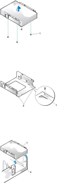
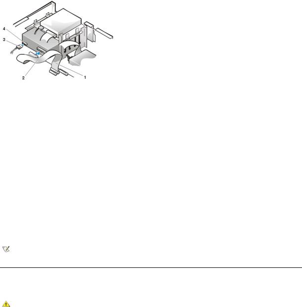
5. Connect a power cable and an interface cable to the appropriate connectors on the back of the drive (see Figure 3).
Figure 3. Attaching Cables to a CD-ROM Drive in the Small-Form-Factor Chassis
1Interface cable
2Power cable
3Power input connector
4Interface connector
Check all cable connections. Fold cables out of the way to provide airflow for the fan and cooling vents.
6.Replace the computer cover; reconnect your computer and peripherals to their electrical outlets, and turn them on.
7.Update your system configuration information.
Set the Drive 0 option under Drives: Secondary to Auto. See "Primary Drive n and Secondary Drive n" for more information.
8.Verify that your system works correctly by running the Dell Diagnostics.
Installing a Diskette, Tape, or CD-ROM Drive in a Low-Profile Chassis
To install a diskette, tape, or CD-ROM drive in a 5.25-inch drive bay in a low-profile chassis, perform the following steps.
CAUTION: To avoid the possibility of electric shock, turn off the computer and any peripherals, disconnect them from their electrical outlets, and then wait at least 5 seconds before you remove the computer cover. Also, before you install a drive, see the other precautions in "Safety First—For You and Your Computer."
1.Unpack the drive and prepare it for installation.
NOTICE: To avoid possibly damaging the drive by electromagnetic static (EMS), ground yourself by touching an unpainted metal surface on the back of the computer.
Check the documentation that accompanied the drive to verify that the drive is configured for your computer system. Change any settings necessary for your configuration.
If you are installing an enhanced integrated drive electronics (EIDE) drive, configure the drive for the cable select setting. You usually configure a drive for cable select by setting a jumper or switch, depending on the drive. For instructions on configuring the cable select setting, see the documentation that accompanied the drive.
2.Remove the computer cover as instructed in "Removing and Replacing the Computer Cover."
3.Remove the 3.5-inch diskette drive/bracket assembly.
Facing the front of the computer, press outward on the two tabs on the left side of the drive bay to disengage the bracket from the chassis (see Figure 4). Then rotate the bracket upward, and remove it from the chassis.
Figure 4. Removing the 3.5-Inch Diskette Drive/Bracket Assembly
1Tabs (2)
2Notches (2)
4. Lift the 5.25-inch drive bracket straight up and out of the chassis (see Figure 5).
If a drive is already installed in the bay and you are replacing it, be sure to disconnect the DC power cable and interface cable from the back of the drive before you remove the drive/bracket assembly. To remove the old drive from the bracket, turn the drive/bracket assembly upside down and unscrew the four screws that secure the drive to the bracket (see Figure 5).
Figure 5. Removing the 5.25-Inch Drive Bracket
1 Screws (4)
5. Attach the bracket to the new drive.
a.Turn the drive upside down, and locate the four screw holes around its perimeter. Fit the bracket over the drive so that the notched end aligns with the front of the drive. Use the score marks on the drive bracket to help align the screw holes on the drive with the screw holes on the bracket (see Figure 6).
Figure 6. Installing a Drive in the 5.25-Inch Drive Bracket
1Score mark
2Notches (2)
b.To further ensure proper positioning of the drive in the bracket, insert and tighten all four screws in the order in which the holes are numbered (the holes are marked "1" through "4").
6.Reinstall the 5.25-inch diskette drive/bracket assembly in the chassis.
Align the notches on the front of the drive bracket (see Figure 6) with the front of the computer. Hold the bracket level, and lower the assembly straight down into place (see Figure 7).
Figure 7. Inserting the Drive/Bracket Assembly Into the Drive Bay
1Bracket
2Notches (2)
7.If you are installing a drive that has its own controller card, install the controller card in an expansion slot.
8.Connect a DC power cable to the power input connector on the back of the drive (see Figure 8).
9. Connect the appropriate interface cable to the interface connector on the back of the drive (see Figure 8).
If your system came with an enhanced integrated drive electronics (EIDE) CD-ROM or tape drive, use the spare connector on the existing interface cable. Otherwise, use the EIDE interface cable provided in the drive kit.
Figure 8. Attaching Cables to a Drive in the 5.25-Inch Drive Bay
1Diskette/tape drive interface cable
2Interface connector
3DC power cable
4Power input connector
10. Connect the interface cable to the system board or a controller card, depending on the type of drive.
•For an EIDE tape drive or CD-ROM drive, connect the other end of the interface cable to the interface connector labeled "IDE2" on the system board (see Figure 7 in "Inside Your Computer").
•For a diskette drive or non-EIDE tape drive, connect the cable from the drive to the interface connector labeled "DSKT" on the system board (see Figure 7 in "Inside Your Computer").
•For a drive that comes with its own controller card, connect the other end of the interface cable to the controller card.
Check all cable connections. Fold cables out of the way to provide airflow for the fan and cooling vents.
11.If the 5.25-inch drive bay was previously empty, remove the front-panel insert from the front bezel.
12.Replace the computer cover; reconnect your computer and peripherals to their electrical outlets, and turn them on.
13.Update your system configuration information.
•For a diskette drive, enter System Setup and update the appropriate Diskette Drive A or Diskette Drive B option to reflect the size and capacity of your new diskette drive.
•If you installed a non-EIDE tape drive as the second drive, set the Diskette Drive B option to Not Installed.
•For EIDE CD-ROM and tape drives, set the appropriate Drive option (0 or 1) under Drives: Secondary to Auto. See "Primary Drive n and Secondary Drive n" for more information.
14.Verify that your system works correctly by running the Dell Diagnostics.
NOTE: Tape drives sold by Dell come with their own operating software and documentation. After you install a tape drive, refer to the documentation that came with the drive for instructions on installing and using the tape drive software.
Installing a Diskette, Tape, or CD-ROM Drive in a Midsize or Mini Tower Chassis
To install a diskette, tape, or CD-ROM drive in a 5.25-inch drive bay, perform the following steps.
CAUTION: To avoid the possibility of electric shock, turn off the computer and any peripherals, disconnect them from their electrical outlets, and then wait at least 5 seconds before you remove the computer cover. Also, before you install a drive, see the other precautions in "Safety First—For You and Your Computer."
1.Unpack the drive and prepare it for installation.
NOTICE: To avoid possibly damaging the drive by electromagnetic static (EMS), ground yourself by touching an unpainted metal surface on the back of the computer.
Check the documentation that accompanied the drive to verify that the drive is configured for your computer system. Change any settings necessary for your configuration.
If you are installing an enhanced integrated drive electronics (EIDE) drive, configure the drive for the cable select setting. The cable select setting is located on the drive. To configure the cable select setting, see the documentation that accompanied the drive.
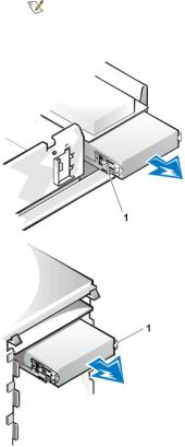
2.Remove the computer cover as instructed in "Removing and Replacing the Computer Cover."
3.Remove the front bezel (mini tower only) as instructed in "Removing and Replacing the Front Bezel."
4.Remove the drive bracket from the bay you want to use.
a.Squeeze the metal tabs that extend from each side of the drive bracket toward each other, and pull the bracket out of the bay (see Figure 9).
NOTE: For easier access inside the chassis, you may want to rotate the power supply out of the way temporarily.
Figure 9. Removing a Drive
1 Bracket tabs (2)
If a drive is already installed in the bay and you are replacing it, disconnect the DC power cable and interface cable from the back of the drive before you slide the bracket out of the bay.
b.To remove the installed drive from the bracket, turn the drive/bracket assembly upside down and unscrew the four screws that secure the drive to the bracket (see Figure 10).
5.Attach the bracket to the replacement drive.
a.Turn the drive upside down, and locate the four screw holes around its perimeter.
b.Fit the bracket over the drive, and then tilt the front of the drive up so that the bracket drops down into place.
c.To ensure proper installation, align all screw holes and ensure that the tabs on the front of the bracket are flush with the front of the drive (see Figure 10).
Figure 10. Attaching the Drive Bracket to the New Drive

15.25-inch drive
2Bracket tabs (2)
3Bracket
d.To further ensure proper positioning of the drive in the bracket, insert and tighten all four screws in the order in which the holes are numbered (the holes are labeled "1" through "4").
6.Slide the drive into the drive bay until the drive snaps securely into place (see Figure 11). Make sure that both bracket tabs snap into place in the drive bay.
Figure 11. Inserting the New Drive Into the Drive Bay
1 5.25-inch drive
7.Connect a DC power cable to the power input connector on the back of the drive (see Figure 12).
8.Connect the appropriate interface cable to the interface connector on the back of the drive (see Figure 12).
If your system came with an EIDE CD-ROM or tape drive, use the spare connector on the existing interface cable. Otherwise, use the EIDE interface cable provided in the drive kit.
NOTICE: You must match the colored strip on the cable with pin 1 on the drive's interface connector to avoid possible damage to your system.
Figure 12. Attaching Diskette Drive or Tape Drive Cables
1DC power cable
2Power input connector
3Interface connector
4Diskette/tape drive interface cable
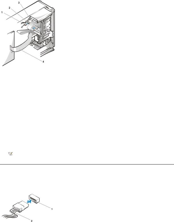
Connect the interface cable to the system board.
•For an EIDE tape drive or CD-ROM drive, connect the other end of the interface cable to the interface connector labeled "IDE2" on the system board (see Figure 9 in "Inside Your Computer").
•For a diskette drive, connect the cable from the drive to the interface connector labeled "DSKT" on the system board (see Figure 9 in "Inside Your Computer").
Check all cable connections. Fold cables out of the way to provide airflow for the fan and cooling vents.
10.If the 5.25-inch drive bay was previously empty, remove the front-panel insert from the front bezel.
11.Replace the front bezel (mini tower only).
12.Replace the computer cover, reconnect your computer and peripherals to their electrical outlets, and turn them on.
13.Update your system configuration information in System Setup.
•For a diskette drive, update the appropriate Diskette Drive option (A or B) to reflect the size and capacity of your new diskette drive.
•For EIDE CD-ROM and tape drives, set the appropriate Secondary Drive option (0 or 1) to Auto.
14.Verify that your system works correctly by running the Dell Diagnostics.
NOTE: Tape drives sold by Dell come with their own operating software and documentation. After you install a tape drive, refer to the documentation that came with the drive for instructions on installing and using the tape drive software.
Connecting Drives
When you install a drive, you connect two cables—a DC power cable and an interface cable—to the back of the drive. Your drive’s power input connector (to which you connect the DC power cable) resembles the connector shown in Figure 13.
Figure 13. Power Cable Connector
1Power input connector
2Power cable
The drive’s interface connector is a card-edge connector or a header connector, as shown in Figure 14.
Figure 14. Drive Interface Connectors
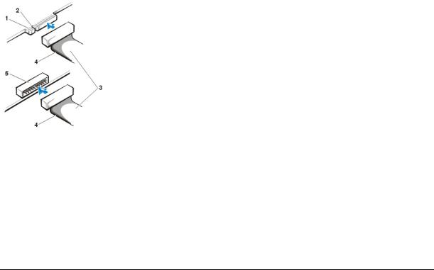
1Card-edge connector on drive
2Notch
3Interface cables
4Colored strip
5Header connector on drive
When you attach the interface cable to a drive, be sure to match the colored strip on the cable to pin 1 of the drive’s interface connector. For the location of pin 1 on the drive’s interface connector, see the documentation that came with the drive.
When you disconnect an interface cable from the system board, be sure to press in on the locking tabs on the cable connector before you disconnect the cable. When you attach an interface cable to the system board, be sure that the locking tabs snap into place so that the cable is firmly attached to the connector on the system board.
Most interface connectors are keyed for correct insertion; that is, a notch or a missing pin on one connector matches a tab or a filled-in hole on the other connector (see Figure 14). Keyed connectors ensure that the pin-1 wire in the cable (indicated by the colored strip along one edge of the cable) goes to the pin-1 end of the connector.
The pin-1 end of a connector on a board or a card is usually indicated by a silk-screened "1" printed directly on the board or card.
NOTICE: When you connect an interface cable, do not reverse the interface cable (do not place the colored strip away from pin 1 of the connector). Reversing the cable prevents the drive from operating and could damage the controller, the drive, or both.
Back to Contents Page

Back to Contents Page
Drivers and Utilities: Dell™ OptiPlex™ GX110 System User's Guide
Program Diskette Maker |
Intel INF Chipset Update Utility for Windows 95 or Windows 98 |
Video Drivers |
Mouse Drivers |
NIC Drivers |
System Utilities |
Bus-Mastering EIDE Driver for Windows NT 4.0 or Windows 98 |
|
|
|
Program Diskette Maker
Dell installed all the drivers for any integrated devices as well as the system utilities on your system's hard-disk drive. These drivers and utilities are provided in diskette image form, from which you can make backup diskettes using the Program Diskette Maker. Dell strongly urges that you make these backup diskettes as soon as you complete initial system setup in case you need to reinstall one of these drivers or utilities.
The Program Diskette Maker is located in the Dell Accessories program folder and contains complete online documentation on its use. To access the Program Diskette Maker, perform the following steps:
1.Start your operating system.
2.Click Start, and then click Programs.
3.Click Dell Accessories.
4.Click Program Disk Maker.
Video Drivers
To reinstall the video drivers, perform the following steps:
1.Use the Program Diskette Maker (located in the Dell Accessories program folder) to make a diskette copy of the video drivers installed on your hard-disk drive.
2.Insert the video driver diskette 1 into the diskette drive.
3.Click the Start button, click Run, type a:\setup in the Run window, and then click OK.
4.Follow the instructions that appear on your screen to complete the installation.
NIC Drivers
This section describes how to reinstall the network interface controller (NIC) driver for the following operating systems:
•Microsoft® Windows NT® 4.0
•Microsoft Windows® 98
•Microsoft Windows 95
Windows NT 4.0 NIC Driver
The Windows NT 4.0 operating system installed by Dell automatically detects and installs the NIC driver. To reinstall the driver, perform the following steps:
1.Use the Program Diskette Maker (located in the Dell Accessories program folder) to make a diskette copy of the NIC drivers installed on your hard-disk drive.
2.Connect the network cable to the back of your computer. See "Network Cable Requirements" for detailed instructions.
3.Verify that the NIC is enabled in System Setup.
See "Network Interface Controller" for more information.

4.Start the Windows NT operating system, and log on as an administrator or as a user with administrator privileges. For information on administrator privileges, see your Windows NT documentation.
5.Double-click the My Computer icon, double-click Control Panel, and then double-click the Network icon.
NOTE: If you are installing networking on your system for the first time, the Windows NT operating system displays a message asking if you want to install networking. Click Yes, and refer to your Windows NT documentation for instructions.
6.Click the Adapters tab in the Network Control Panel, and then click Update.
7.Insert the NIC driver diskette 1 into drive A, type a:\, and then click Continue.
8.When prompted, remove the NIC driver diskette 1 from the diskette drive and insert the NIC driver diskette 2.
9.Remove the diskette from drive A, and click Yes in the Network Settings Change window to restart your system.
Windows 98 NIC Driver
To install the NIC driver for Windows 98, perform the following steps:
1.Use the Program Diskette Maker (located in the Dell Accessories program folder) to make a diskette copy of the NIC drivers installed on your hard-disk drive.
2.Connect the network cable to the back of your computer. See "Network Cable Requirements" for detailed instructions.
3.Verify that the integrated NIC is enabled and connected to its network. See "Network Interface Controller" for more information.
4.Start the Windows 98 operating system.
5.Click the Start button, point to Settings, and click Control Panel. Then double-click the System icon.
6.In the System Properties window, click the Device Manager tab.
7.If you are updating or reinstalling the driver for a Dell-installed Windows 98 operating system, click Network Adapters, and then click 3Com 3C920 Integrated Fast Ethernet Controller (3C905C-TX Compatible).
If you are installing the driver for a new Windows 98 installation, click Other Devices, and then click PCI Ethernet Controller.
8.Click Properties.
9.Click the Driver tab.
10.Click the Update Driver button.
The Update Device Driver Wizard window appears.
11.Click Next.
12.Select Display a list of drivers in a specific location, so you can select the driver you want, and click Next.
If you are installing the driver for a new Windows 98 installation, select Network Adapters from the list of device types. Then click OK.
13.Click the Have Disk button.
14.Insert the NIC driver diskette 1 into drive A, verify that a:\ is specified as the target location, and click OK.
15.Verify that 3Com 3C920 Integrated Fast Ethernet Controller (3C905C-TX Compatible) is selected, and then click OK.
16.When the Update Device Driver Wizard asks where to install the driver, click Next.
17.When prompted, remove the NIC driver diskette 1 and insert the NIC driver diskette 2. Then click OK.
18.Click Finish.
19.When prompted to restart your system, remove the diskette from drive A, and click Yes.
Windows 95 NIC Driver
The Windows 95 operating system installed by Dell automatically detects and installs the NIC driver. This subsection provides instructions for
 Loading...