


Inspiron 15-5567
Table of contents
 Loading...
Inspiron 15 5000
Service Manual
Computer Model: Inspiron 15-5567
Regulatory Model: P66F
Regulatory Type: P66F001

Notes, cautions, and warnings
NOTE: A NOTE indicates important information that helps you make better
use of your product.
CAUTION: A CAUTION indicates either potential damage to hardware or loss
of data and tells you how to avoid the problem.
WARNING: A WARNING indicates a potential for property damage, personal
injury, or death.
© 2016 Dell Inc. All rights reserved. This product is protected by U.S. and international
copyright and intellectual property laws. Dell and the Dell logo are trademarks of Dell Inc. in
the United States and/or other jurisdictions. All other marks and names mentioned herein may
be trademarks of their respective companies.
2016 - 09
Rev. A01

Contents
Before working inside your computer.................................. 10
Before you begin .............................................................................................10
Safety instructions............................................................................................10
Recommended tools........................................................................................11
Screw list...........................................................................................................12
After working inside your computer......................................14
Removing the optical drive......................................................15
Procedure.........................................................................................................15
Replacing the optical drive......................................................18
Procedure.........................................................................................................18
Removing the base cover.........................................................19
Prerequisites.....................................................................................................19
Procedure........................................................................................................ 20
Replacing the base cover.........................................................23
Procedure.........................................................................................................23
Post-requisites................................................................................................. 23
Removing the memory modules............................................24
Prerequisites.....................................................................................................24
Procedure........................................................................................................ 24
Replacing the memory modules............................................ 26
Procedure........................................................................................................ 26
Post-requisites................................................................................................. 27
3

Removing the wireless card.................................................... 28
Prerequisites.................................................................................................... 28
Procedure........................................................................................................ 28
Replacing the wireless card.....................................................30
Procedure........................................................................................................ 30
Post-requisites................................................................................................. 31
Removing the optical-drive interposer.................................32
Prerequisites.....................................................................................................32
Procedure.........................................................................................................32
Replacing the optical-drive interposer.................................34
Procedure........................................................................................................ 34
Post-requisites.................................................................................................34
Removing the coin-cell battery..............................................35
Prerequisites.....................................................................................................35
Procedure.........................................................................................................35
Replacing the coin-cell battery.............................................. 37
Procedure.........................................................................................................37
Post-requisites................................................................................................. 37
Removing the I/O board.......................................................... 38
Prerequisites.....................................................................................................38
Procedure........................................................................................................ 38
Replacing the I/O board.......................................................... 40
Procedure........................................................................................................ 40
Post-requisites.................................................................................................40
4

Removing the hard drive..........................................................41
Prerequisites.....................................................................................................41
Procedure.........................................................................................................41
Replacing the hard drive..........................................................44
Procedure........................................................................................................ 44
Post-requisites.................................................................................................44
Removing the battery...............................................................45
Prerequisites.....................................................................................................45
Procedure........................................................................................................ 45
Replacing the battery............................................................... 48
Procedure........................................................................................................ 48
Post-requisites.................................................................................................48
Removing the status-light board........................................... 49
Prerequisites.................................................................................................... 49
Procedure........................................................................................................ 49
Replacing the status-light board............................................51
Procedure.........................................................................................................51
Post-requisites................................................................................................. 51
Removing the speakers............................................................ 52
Prerequisites.....................................................................................................52
Procedure.........................................................................................................52
Replacing the speakers............................................................ 54
Procedure........................................................................................................ 54
Post-requisites.................................................................................................54
5

Removing the system-board assembly................................. 55
Prerequisites.....................................................................................................55
Procedure.........................................................................................................55
Replacing the system-board assembly................................. 60
Procedure........................................................................................................ 60
Post-requisites................................................................................................. 61
Removing the heat-sink assembly......................................... 62
Prerequisites.....................................................................................................62
Procedure........................................................................................................ 62
Replacing the heat-sink assembly......................................... 64
Procedure........................................................................................................ 64
Post-requisites.................................................................................................64
Removing the touch pad......................................................... 66
Prerequisites.................................................................................................... 66
Procedure........................................................................................................ 66
Replacing the touch pad..........................................................70
Procedure........................................................................................................ 70
Post-requisites.................................................................................................70
Removing the display assembly..............................................72
Prerequisites.....................................................................................................72
Procedure.........................................................................................................72
Replacing the display assembly..............................................76
Procedure.........................................................................................................76
Post-requisites................................................................................................. 76
6

Removing the display bezel.....................................................77
Prerequisites.....................................................................................................77
Procedure.........................................................................................................77
Replacing the display bezel.....................................................79
Procedure.........................................................................................................79
Post-requisites................................................................................................. 79
Removing the camera.............................................................. 80
Prerequisites.................................................................................................... 80
Procedure........................................................................................................ 80
Replacing the camera...............................................................82
Procedure........................................................................................................ 82
Post-requisites.................................................................................................82
Removing the display panel.................................................... 83
Prerequisites.....................................................................................................83
Procedure........................................................................................................ 83
Replacing the display panel.................................................... 86
Procedure........................................................................................................ 86
Post-requisites.................................................................................................86
Removing the display hinges.................................................. 87
Prerequisites.....................................................................................................87
Procedure.........................................................................................................87
Replacing the display hinges.................................................. 89
Procedure........................................................................................................ 89
Post-requisites.................................................................................................89
7

Removing the display cable.................................................... 90
Prerequisites.................................................................................................... 90
Procedure........................................................................................................ 90
Replacing the display cable.....................................................92
Procedure........................................................................................................ 92
Post-requisites.................................................................................................92
Removing the display back-cover and antenna
assembly......................................................................................93
Prerequisites.....................................................................................................93
Procedure........................................................................................................ 93
Replacing the display back-cover and antenna
assembly......................................................................................95
Procedure........................................................................................................ 95
Post-requisites.................................................................................................95
Removing the power-button module...................................96
Prerequisites.................................................................................................... 96
Procedure........................................................................................................ 96
Replacing the power-button module................................... 98
Procedure........................................................................................................ 98
Post-requisites.................................................................................................98
Removing the power-adapter port........................................99
Prerequisites.................................................................................................... 99
Procedure........................................................................................................ 99
Replacing the power-adapter port...................................... 101
Procedure.......................................................................................................101
Post-requisites............................................................................................... 101
8

Removing the palm rest and keyboard assembly............. 102
Prerequisites...................................................................................................102
Procedure...................................................................................................... 102
Replacing the palm rest and keyboard assembly..............104
Procedure...................................................................................................... 104
Post-requisites...............................................................................................104
Diagnostics............................................................................... 105
Getting help and contacting Dell.........................................107
Self-help resources........................................................................................107
Contacting Dell..............................................................................................107
9
Before working inside your
computer
NOTE: The images in this document may differ from your computer
depending on the configuration you ordered.
Before you begin
1 Save and close all open files and exit all open applications.
2 Shut down your computer. Click Start → Power → Shut down.
NOTE: If you are using a different operating system, see the
documentation of your operating system for shut-down
instructions.
3 Disconnect your computer and all attached devices from their electrical
outlets.
4 Disconnect all cables such as telephone cables and network cables, from
your computer.
5 Disconnect all attached devices and peripherals, such as keyboard,
mouse, and monitor, from your computer.
6 Remove any media card and optical disc from your computer, if
applicable.
7 Close the display and turn the computer over.
Safety instructions
Use the following safety guidelines to protect your computer from potential
damage and ensure your personal safety.
WARNING: Before working inside your computer, read the safety
information that shipped with your computer. For more safety best
practices, see the Regulatory Compliance home page at
www.dell.com/regulatory_compliance.
10

WARNING: Disconnect all power sources before opening the
computer cover or panels. After you finish working inside the
computer, replace all covers, panels, and screws before connecting to
the electrical outlet.
CAUTION: To avoid damaging the computer, ensure that the work
surface is flat and clean.
CAUTION: To avoid damaging the components and cards, handle
them by their edges, and avoid touching pins and contacts.
CAUTION: You should only perform troubleshooting and repairs as
authorized or directed by the Dell technical assistance team. Damage
due to servicing that is not authorized by Dell is not covered by your
warranty. See the safety instructions that shipped with the product or
at www.dell.com/regulatory_compliance.
CAUTION: Before touching anything inside your computer, ground
yourself by touching an unpainted metal surface, such as the metal at
the back of the computer. While you work, periodically touch an
unpainted metal surface to dissipate static electricity, which could
harm internal components.
CAUTION: When you disconnect a cable, pull on its connector or on
its pull tab, not on the cable itself. Some cables have connectors with
locking tabs or thumb-screws that you must disengage before
disconnecting the cable. When disconnecting cables, keep them
evenly aligned to avoid bending any connector pins. When connecting
cables, ensure that the ports and connectors are correctly oriented
and aligned.
CAUTION: Press and eject any installed card from the media-card
reader.
Recommended tools
The procedures in this document may require the following tools:
• Phillips screwdriver
• Plastic scribe
11

Screw list
Component Secured to Screw type Quantity Screw
image
Base cover Palm rest and
keyboard
assembly
M2x2 Big
Head
3
Base cover Palm rest and
keyboard
assembly
M2x4 2
Base cover Palm rest and
keyboard
assembly
M2.5x8 13
Battery Palm rest and
keyboard
assembly
M2.5x5 1
Fan Palm rest and
keyboard
assembly
M2.5x5 1
Hard drive Hard-drive
bracket
M3x3 4
Hard-drive
bracket
Palm rest and
keyboard
assembly
M2.5x5 3
Heat-sink
assembly
System board M2x3 3
Hinge brackets Display back-
cover and
antenna
assembly
M2.5x3 6
Hinge brackets Palm rest and
keyboard
assembly
M2.5x5 4
Hinge (LCD
side)
Display back-
cover and
antenna
assembly
M2x3 2
12

Component Secured to Screw type Quantity Screw
image
I/O board Palm rest and
keyboard
assembly
M2.5x5 1
Optical-drive
bracket
Optical drive M2x3 2
Optical-drive
interposer
Palm rest and
keyboard
assembly
M2x2 Big
Head
2
Palm rest and
keyboard
assembly
bridge
Palm rest and
keyboard
assembly
M2.5x5 2
Panel Palm rest and
keyboard
assembly
M2x3 4
Power-
adapter port
Palm rest and
keyboard
assembly
M2x3 1
Power-button
board
Palm rest and
keyboard
assembly
M2x2 Big
Head
1
System board Palm rest and
keyboard
assembly
M2.5x5 1
Touch pad Palm rest and
keyboard
assembly
M2x2 4
Touch-pad
bracket
Palm rest and
keyboard
assembly
M2x2 3
Wireless-card
bracket
System board M2x3 1
13

After working inside your
computer
CAUTION: Leaving stray or loose screws inside your computer may
severely damage your computer.
1 Replace all screws and ensure that no stray screws remain inside your
computer.
2 Connect any external devices, peripherals, or cables you removed before
working on your computer.
3 Replace any media cards, discs, or any other parts that you removed
before working on your computer.
4 Connect your computer and all attached devices to their electrical
outlets.
5 Turn on your computer.
14

Removing the optical drive
WARNING: Before working inside your computer, read the safety
information that shipped with your computer and follow the steps in
Before working inside your computer. After working inside your
computer, follow the instructions in After working inside your
computer. For more safety best practices, see the Regulatory
Compliance home page at
www.dell.com/regulatory_compliance.
Procedure
1 Remove the screw that secures the optical-drive assembly to the base
cover.
2 Using a plastic scribe, push the optical drive through the screw hole to
release the optical-drive assembly.
15

3 Slide the optical-drive assembly out of the optical-drive bay.
1 optical-drive assembly 2 M2x4 screw
3 plastic scribe 4 base cover
4 Remove the screws that secure the optical-drive bracket to the optical
drive.
16

5 Remove the optical-drive bracket.
1 optical drive 2 M2x3 screws (2)
3 optical-drive bracket
6 Pull the optical-drive bezel carefully to remove it from the optical drive.
1 optical-drive bezel 2 optical drive
3 tabs (3)
17

Replacing the optical drive
WARNING: Before working inside your computer, read the safety
information that shipped with your computer and follow the steps in
Before working inside your computer. After working inside your
computer, follow the instructions in After working inside your
computer. For more safety best practices, see the Regulatory
Compliance home page at
www.dell.com/regulatory_compliance.
Procedure
1 Align the tabs on the optical-drive bezel with the slots on the optical
drive and snap the optical-drive bezel into place.
2 Align the screw holes on the optical-drive bracket with the screw holes
on the optical drive.
3 Replace the screws that secure the optical-drive bracket to the optical
drive.
4 Slide the optical-drive assembly into the optical-drive bay.
5 Align the screw hole on the optical-drive bracket with the screw hole on
the base cover.
6 Replace the screw that secures the optical-drive assembly to the base
cover.
18

Removing the base cover
WARNING: Before working inside your computer, read the safety
information that shipped with your computer and follow the steps in
Before working inside your computer. After working inside your
computer, follow the instructions in After working inside your
computer. For more safety best practices, see the Regulatory
Compliance home page at
www.dell.com/regulatory_compliance.
Prerequisites
Remove the optical drive.
19

Procedure
1 Remove the screws that secure the base cover to the palm rest and
keyboard assembly.
1 M2.5x8 screws (13) 2 M2x2 screws (3)
3 M2x4 screw 4 base cover
2 Using a plastic scribe, pry the base cover starting from the top-left corner
of the computer base.
20

3 Lift the base cover off the palm rest and keyboard assembly at an angle.
1 palm rest and keyboard
assembly
2 plastic scribe
3 base cover
NOTE: Follow step 4 and 5 only if you want to further remove any
component from the computer.
21
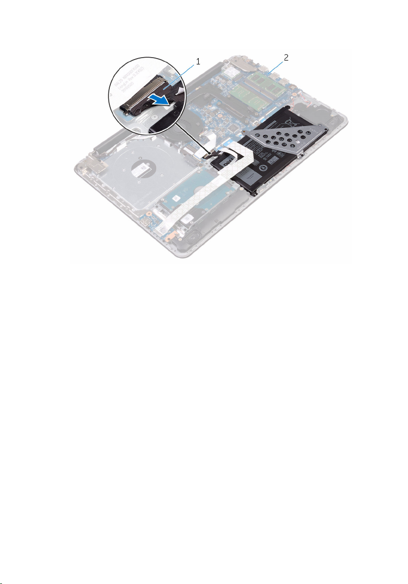
4 Disconnect the battery cable from the system board.
1 battery cable 2 system board
5 Press and hold the power button for 5 seconds to ground the system
board.
22

Replacing the base cover
WARNING: Before working inside your computer, read the safety
information that shipped with your computer and follow the steps in
Before working inside your computer. After working inside your
computer, follow the instructions in After working inside your
computer. For more safety best practices, see the Regulatory
Compliance home page at
www.dell.com/regulatory_compliance.
Procedure
1 Connect the battery cable to the system board, if applicable.
2 Place the base cover on the palm rest and keyboard assembly and snap
the base cover into place.
3 Replace the screws that secure the base cover to the palm rest and
keyboard assembly.
Post-requisites
Replace the optical drive.
23

Removing the memory
modules
WARNING: Before working inside your computer, read the safety
information that shipped with your computer and follow the steps in
Before working inside your computer. After working inside your
computer, follow the instructions in After working inside your
computer. For more safety best practices, see the Regulatory
Compliance home page at www.dell.com/regulatory_compliance.
Prerequisites
1 Remove the optical drive.
2 Remove the base cover.
Procedure
1 Use your fingertips to carefully spread apart the securing-clips on each
end of the memory-module slot until the memory module pops up.
24

2 Remove the memory module from the memory-module slot.
1 securing clips (2) 2 memory module
3 memory-module slot
25

Replacing the memory
modules
WARNING: Before working inside your computer, read the safety
information that shipped with your computer and follow the steps in
Before working inside your computer. After working inside your
computer, follow the instructions in After working inside your
computer. For more safety best practices, see the Regulatory
Compliance home page at www.dell.com/regulatory_compliance.
Procedure
1 Align the notch on the memory module with the tab on the memory-
module slot.
26
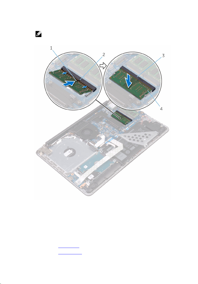
2 Slide the memory module firmly into the slot at an angle and press the
memory module down until it clicks into place.
NOTE: If you do not hear the click, remove the memory module
and reinstall it.
1 notch 2 tab
3 memory-module slot 4 memory module
3 Connect the battery cable to the system board.
Post-requisites
1 Replace the base cover.
2 Replace the optical drive.
27

Removing the wireless card
WARNING: Before working inside your computer, read the safety
information that shipped with your computer and follow the steps in
Before working inside your computer. After working inside your
computer, follow the instructions in After working inside your
computer. For more safety best practices, see the Regulatory
Compliance home page at
www.dell.com/regulatory_compliance.
Prerequisites
1 Remove the optical drive.
2 Remove the base cover.
Procedure
1 Remove the screw that secures the wireless-card bracket to the system
board.
2 Slide and remove the wireless-card bracket and disconnect the antenna
cables from the wireless card.
28
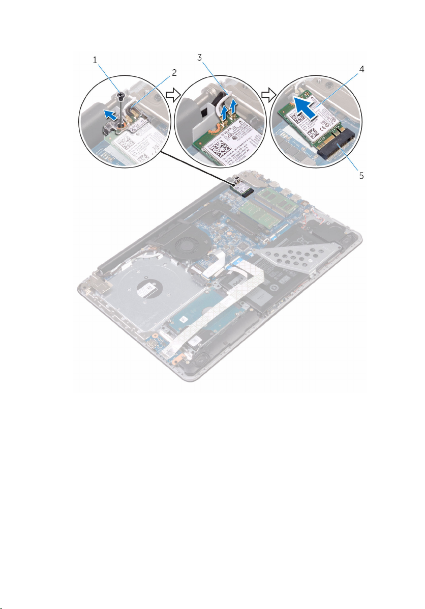
3 Slide and remove the wireless card from the wireless-card slot.
1 M2x3 screw 2 wireless-card bracket
3 antenna cables (2) 4 wireless card
5 wireless-card slot
29
Replacing the wireless card
WARNING: Before working inside your computer, read the safety
information that shipped with your computer and follow the steps in
Before working inside your computer. After working inside your
computer, follow the instructions in After working inside your
computer. For more safety best practices, see the Regulatory
Compliance home page at
www.dell.com/regulatory_compliance.
Procedure
CAUTION: To avoid damage to the wireless card, do not place any
cables under it.
1 Align the notch on the wireless card with the tab on the wireless-card
slot.
2 Insert the wireless card at an angle into the wireless-card slot.
3 Connect the antenna cables to the wireless card.
The following table provides the antenna-cable color scheme for the
wireless card supported by your computer.
Connectors on the wireless card Antenna-cable color
Main (white triangle) White
Auxiliary (black triangle) Black
4 Slide and replace the wireless-card bracket on the wireless-card slot.
5 Align the screw hole on the wireless-card bracket with the screw hole on
the wireless card and the palm rest and keyboard assembly.
30
Loading...