


 Loading...
'HOOŠ 2SWL3OH[Š *;574 6\VWHPV
86(5·6 *8,'(
®
Information in this document is subject to change without notice. © 1991–1996 Dell Computer Corporation. All rights reserved.
Reproduction in any manner whatsoever without the written permission of Dell Computer Corporation is strictly forbidden.
Trademarks used in this text: Dell, the DELL logo, and OptiPlex are registered trademarks and DellWare is a registered service mark of Dell Computer Corporation; Intel and Pentium are registered trademarks and Intel486, Intel386, IntelDX2, and IntelDX4 are trademarks of Intel Corporation; Windows for Workgroups is a trademark and Microsoft, MS-DOS, Windows, and Windows NT are registered trademarks of Microsoft Corporation; IBM and OS/2 are registered trademarks of International Business Machines Corporation; UNIX is a registered trademark of UNIX System Laboratories, Inc., a wholly owned subsidiary of Novell, Inc.; Novell and NetWare are registered trademarks of Novell, Inc.; VESA is a registered trademark and VL-Bus is a trademark of Video Electronics Standards Association; 3Com is a registered trademark of 3Com Corporation.
Other trademarks and trade names may be used in this document to refer to either the entities claiming the marks and names or their products. Dell Computer Corporation disclaims any proprietary interest in trademarks and trade names other than its own.
September 1996 P/N 99153 Rev. A02

Safety Instructions
Use the following safety guidelines to help protect your computer’s system from potential damage and to ensure your own personal safety.
When Using Your Computer System
As you use your computer system, observe the following safety guidelines:
•To help avoid damaging your computer, be sure the voltage selection switch on the power supply is set to match the alternating current (AC) power available at your location:
—115 volts (V)/60 hertz (Hz) in most of North and South America and some Far Eastern countries such as Japan, South Korea, and Taiwan
—230 V/50 Hz in most of Europe, the Middle
East, and the Far East
Also be sure your monitor and attached peripherals are electrically rated to operate with the AC power available in your location.
•To help avoid possible damage to the system board, wait five seconds after turning off the system before removing a component from the system board or disconnecting a peripheral device from the computer.
•To help prevent electric shock, plug the computer and peripheral power cables into properly grounded power sources. These cables are equipped with 3- prong plugs to ensure proper grounding. Do not use adapter plugs or remove the grounding prong from a cable. If you must use an extension cable, use a 3- wire cable with properly grounded plugs.
•To help protect your computer system from sudden, transient increases and decreases in electrical power, use a surge suppressor, line conditioner, or uninterruptible power supply.
•Be sure nothing rests on your computer system’s cables and that the cables are not located where they can be stepped on or tripped over.
•Do not spill food or liquids on your computer. If the computer gets wet, consult your Diagnostics and Troubleshooting Guide.
•Do not push any objects into the openings of your computer. Doing so can cause fire or electric shock by shorting out interior components.
•Keep your computer away from radiators and heat sources. Also, do not block cooling vents. Avoid placing loose papers underneath your computer; do not place your computer in a closed-in wall unit or on a bed, sofa, or rug.
Ergonomic Computing Habits
WARNING: Improper or prolonged keyboard use may result in injury.
For comfort and efficiency, observe the following ergonomic guidelines when setting up and using your computer system:
•Position your system so that the monitor and keyboard are directly in front of you as you work. Special shelves are available (from Dell and other sources) to help you correctly position your keyboard.
•Set the monitor at a comfortable viewing distance (usually 510 to 610 millimeters [20 to 24 inches] from your eyes).
•Make sure the monitor screen is at eye level or slightly lower when you are sitting in front of the monitor.
v

•Adjust the tilt of the monitor, its contrast and brightness settings, and the lighting around you (such as overhead lights, desk lamps, and the curtains or blinds on nearby windows) to minimize reflections and glare on the monitor screen.
•Use a chair that provides good lower back support.
•Keep your forearms horizontal with your wrists in a neutral, comfortable position while using the keyboard or mouse.
•Always leave space to rest your hands while using the keyboard or mouse.
•Let your upper arms hang naturally at your sides.
•Sit erect, with your feet resting on the floor and your thighs level.
•When sitting, make sure the weight of your legs is on your feet and not on the front of your chair seat. Adjust your chair’s height or use a footrest, if necessary, to maintain proper posture.
•Vary your work activities. Try to organize your work so that you do not have to type for extended periods of time. When you stop typing, try to do things that use both hands.
monitor screen at or below eye level
wrists relaxed and flat
monitor and keyboard positioned directly
in front of user
arms at desk level
feet flat on the floor
vi

When Working Inside Your Computer
Before you remove the computer cover, perform the following steps in the sequence indicated:
CAUTIONS: Do not attempt to service the computer system yourself, except as explained in this guide and elsewhere in Dell documentation. Always follow installation and servicing instructions closely.
To help avoid possible damage to the system board, wait five seconds after turning off the system before removing a component from the system board or disconnecting a peripheral device from the computer.
1.Turn off your computer and any peripherals.
2.Disconnect your computer and peripherals from their power sources. Also disconnect any telephone or telecommunication lines from the computer.
Doing so reduces the potential for personal injury or shock.
3.Touch an unpainted metal surface on the chassis, such as the metal around the card-slot openings at the back of the computer, before touching anything inside your computer.
While you work, periodically touch an unpainted metal surface on the computer chassis to dissipate any static electricity that might harm internal components.
In addition, take note of these safety guidelines when appropriate:
•When you disconnect a cable, pull on its connector or on its strain-relief loop, not on the cable itself. Some cables have a connector with locking tabs; if you are disconnecting this type of cable, press in on the locking tabs before disconnecting the cable. As you pull connectors apart, keep them evenly aligned to avoid bending any connector pins. Also, before you connect a cable, make sure both connectors are correctly oriented and aligned.
•Handle components and cards with care. Don’t touch the components or contacts on a card. Hold a card by its edges or by its metal mounting bracket. Hold a component such as a microprocessor chip by its edges, not by its pins.
Protecting Against Electrostatic
Discharge
Static electricity can harm delicate components inside your computer. To prevent static damage, discharge static electricity from your body before you touch any of your computer’s electronic components, such as the microprocessor. You can do so by touching an unpainted metal surface on the computer chassis.
As you continue to work inside the computer, periodically touch an unpainted metal surface to remove any static charge your body may have accumulated.
In addition to the preceding precautions, you can also take the following steps to prevent damage from electrostatic discharge (ESD):
•When unpacking a static-sensitive component from its shipping carton, do not remove the component’s antistatic packing material until you are ready to install the component in your computer. Just before unwrapping the antistatic packaging, be sure to discharge static electricity from your body.
•When transporting a sensitive component, first place it in an antistatic container or packaging.
•Handle all sensitive components in a static-safe area. If possible, use antistatic floor pads and workbench pads.
The following caution may appear throughout this document to remind you of these precautions:
CAUTION: See “Protecting Against Electrostatic Discharge” in the safety instructions at the front of this guide.
vii
viii
Preface
About This Guide
This guide is intended for anyone who uses a Dell OptiPlex GXpro computer system. It can be used by both first-time and experienced computer users who want to learn about the features and operation of the systems or who want to upgrade their computers. The chapters and appendixes are summarized as follows:
•Everyone should read Chapter 1, “Introduction,” for an overview of the system features, a description of the controls and indicators on the front panel, and a general discussion of connecting external devices to the back panel of the computer.
•Everyone should read the first few sections of Chapter 2, “Using the Software Support Utilities,” to find out which Dell utilities and bus-mastering integrated drive electronics (IDE) drivers have been included with the system. Only users who want to use one of the utilities or bus-mastering drivers need to read the rest of Chapter 2.
•Everyone should read the first several sections of Chapter 3, “Using the System Setup Program,” to familiarize themselves with this important program. Only users who want to make configuration changes to their system or who want to use the password features need to read the rest of Chapter 3.
•Users who add or remove an Industry-Standard Architecture (ISA) expansion card should read Chapter 4, “Using the ISA Configuration Utility.”
•Users who want to connect their system to a network should read Chapter 5, “Using the Network Interface Controller.” This chapter provides information on connecting the system to a network, configuring the network interface controller (NIC), installing drivers for the NIC, and running the NIC diagnostics.
•Users who need information on the integrated sound features of the computer system should read Chapter 6, “Using the Integrated Audio Controller.” Chapter 6 provides information on connecting audio equipment to your computer, installing audio drivers, and reconfiguring the integrated audio controller.
•Chapter 7, “Working Inside Your Computer,” Chapter 8, “Installing System Board Options,” and Chapter 9, “Installing Drives,” are intended for users who want to install or remove options inside the computer, such as dual in-line memory modules (DIMMs), expansion cards, or drives.
•Appendix A, “Technical Specifications,” and Appendix B, “Hardware Configuration Features,” are intended primarily as reference material for users interested in learning more about the details of the system. Users who add internal options may need to refer to Appendix B to change jumper or switch settings.
•Appendix C, “ISA Configuration Utility Messages,” describes error messages generated by the ISA Configuration Utility (ICU), possible causes, and corrective actions.
•Appendix D, “Maintaining the System,” describes preventive maintenance procedures that you should perform regularly to keep your computer system in top operating condition.
•Appendix E, “Regulatory Notices,” is for users who are interested in which regulatory agencies have tested and approved the Dell OptiPlex GXpro systems.
•Appendix F, “Warranties and Return Policy,” describes the warranty for your Dell system and the “Total Satisfaction” Return Policy.
ix

•The Glossary provides definitions of terms, acronyms, and abbreviations used in this guide.
Warranty and Return Policy
Information
Dell Computer Corporation (“Dell”) manufactures its hardware products from parts and components that are new or equivalent to new in accordance with industrystandard practices. For information about the Dell warranty for your system, see Appendix F, “Warranties and Return Policy.”
Other Documents You May Need
Besides this User’s Guide, the following documentation is included with your system:
•The Getting Started sheet provides step-by-step instructions for setting up your computer system.
•The Frequently Asked Questions cards provide detailed answers to questions that are often asked by Dell computer users. Be sure to read these cards before calling Dell for technical assistance.
•The Diagnostics and Troubleshooting Guide includes troubleshooting procedures and instructions for using the diskette-based diagnostics to test your computer system.
•The Dell Integrated Audio User’s Guide provides instructions for using the application programs that take advantage of the computer’s integrated sound feature. These programs are installed on your harddisk drive.
•Video card documentation from the card manufacturer describes the video drivers included with the system. Only users who want to use or change a video driver need to read this documentation in detail.
You may also have one or more of the following documents.
NOTE: Documentation updates are sometimes included with your system to describe changes to your system or software. Always read these updates before consulting any
other documentation because the updates often contain the latest information.
•Operating system documentation is included if you ordered your operating system software from Dell. This documentation describes how to install (if necessary), configure, and use your operating system software.
•Documentation is included with any options you purchase separately from your system. This documentation includes information that you need to configure and install these options in your Dell computer. Installation instructions for the options are included in this User’s Guide .
•Technical information files—sometimes called “readme” files—may be installed on your hard-disk drive to provide last-minute updates about technical changes to your system or advanced technical reference material intended for experienced users or technicians.
Notational Conventions
The following subsections list notational conventions used in this document.
Warnings, Cautions, and Notes
Throughout this guide, there may be blocks of text printed in bold type within boxes or in italic type. These blocks are warnings, cautions, and notes, and they are used as follows:
WARNING: A WARNING indicates the potential for bodily harm and tells you how to avoid the problem.
CAUTION: A CAUTION indicates either potential damage to hardware or loss of data and tells you how to avoid the problem.
NOTE: A NOTE indicates important information that helps you make better use of your computer system.
x
Typographical Conventions
The following list defines (where appropriate) and illustrates typographical conventions used as visual cues for specific elements of text throughout this document:
•Keycaps, the labeling that appears on the keys on a keyboard, are presented in uppercase and enclosed in angle brackets.
Example: <ENTER>
•Key combinations are series of keys to be pressed simultaneously (unless otherwise indicated) to perform a single function.
Example: <CTRL><ALT><ENTER>
•All items on a menu screen are presented in the HELVETICA font and in uppercase bold.
Example: SETUP PASSWORD category
•Commands presented in lowercase bold are for reference purposes only and are not intended to be typed at that particular point in the discussion.
Example: “Use the format command to . . . .”
In contrast, commands presented in the Courier font are intended to be typed as part of an instruction.
Example: “Type format a: to format the diskette in drive A.”
•Filenames and directory names are presented in lowercase bold.
Examples: autoexec.bat and c:\windows
•Syntax lines consist of a command and all its possible parameters. Commands are displayed in lowercase bold; variable parameters (those for which you substitute a value) are displayed in lowercase italics; constant parameters are displayed in lowercase bold. The brackets indicate items that are optional.
Example: del [drive:] [path]filename [/p]
•Command lines consist of a command and may include one or more of the command’s possible parameters. Command lines are presented in the Courier font.
Example: del c:\myfile.doc
•Screen text is text that appears on the screen of your monitor or display. It can be a system message, for example, or it can be text that you are instructed to type as part of a command (referred to as a command line). Screen text is presented in the Courier font.
Example: “Type md c:\dos, and then press <ENTER>.”
Example: The following message appears on your screen:
No boot device available
•Variables are placeholders for which you substitute a value. They are presented in italics.
Example: DIMM n (where n represents the DIMM socket designation)
xi
xii
Contents
Chapter 1 |
|
Introduction . . . . . . . . . . . . . . . . . . . . . . . . . . . . . . . . . . . . . . . . . . . |
1-1 |
System Features. . . . . . . . . . . . . . . . . . . . . . . . . . . . . . . . . . . . . . . . . . . . . . . . . . . . . . 1-1 Important Note to Windows 95 Users . . . . . . . . . . . . . . . . . . . . . . . . . . . . . . . . . . . . . 1-3 Using the Floor Stand . . . . . . . . . . . . . . . . . . . . . . . . . . . . . . . . . . . . . . . . . . . . . . . . . 1-3 Front Panel . . . . . . . . . . . . . . . . . . . . . . . . . . . . . . . . . . . . . . . . . . . . . . . . . . . . . . . . . 1-4 Back Panel . . . . . . . . . . . . . . . . . . . . . . . . . . . . . . . . . . . . . . . . . . . . . . . . . . . . . . . . . . 1-5
Connecting External Devices . . . . . . . . . . . . . . . . . . . . . . . . . . . . . . . . . . . . . . . . 1-5
Security Cable Slot. . . . . . . . . . . . . . . . . . . . . . . . . . . . . . . . . . . . . . . . . . . . . . . . 1-5
Getting Help . . . . . . . . . . . . . . . . . . . . . . . . . . . . . . . . . . . . . . . . . . . . . . . . . . . . . . . . 1-6
Chapter 2
Using the Software Support Utilities . . . . . . . . . . . . . . . . . . . . . . . 2-1
Software Support Utilities on Diskette . . . . . . . . . . . . . . . . . . . . . . . . . . . . . . . . . . . . 2-1 Dell-Installed Software Support Utilities . . . . . . . . . . . . . . . . . . . . . . . . . . . . . . . . . . 2-1 Backing Up the Software Support Utilities . . . . . . . . . . . . . . . . . . . . . . . . . . . . . . . . . 2-2 System Utilities and Services . . . . . . . . . . . . . . . . . . . . . . . . . . . . . . . . . . . . . . . . . . . 2-2 Asset Tag Utility . . . . . . . . . . . . . . . . . . . . . . . . . . . . . . . . . . . . . . . . . . . . . . . . . 2-2 Installing the Asset Tag Utility . . . . . . . . . . . . . . . . . . . . . . . . . . . . . . . . . . . 2-2 Using the Asset Tag Utility. . . . . . . . . . . . . . . . . . . . . . . . . . . . . . . . . . . . . . 2-2 Auto Power On Utility . . . . . . . . . . . . . . . . . . . . . . . . . . . . . . . . . . . . . . . . . . . . . 2-3 Installing the Auto Power On Utility . . . . . . . . . . . . . . . . . . . . . . . . . . . . . . 2-3 Dell AutoShutdown Service. . . . . . . . . . . . . . . . . . . . . . . . . . . . . . . . . . . . . . . . . 2-3 How AutoShutdown Works . . . . . . . . . . . . . . . . . . . . . . . . . . . . . . . . . . . . . 2-3 If Your Operating System Locks Up . . . . . . . . . . . . . . . . . . . . . . . . . . . . . . 2-4
Dell Thermal Shutdown Service . . . . . . . . . . . . . . . . . . . . . . . . . . . . . . . . . . . . . 2-4 How Thermal Shutdown Works . . . . . . . . . . . . . . . . . . . . . . . . . . . . . . . . . . 2-4 Installing the Dell AutoShutdown and Thermal Shutdown Services. . . . . . . . . . 2-4 Removing a Service . . . . . . . . . . . . . . . . . . . . . . . . . . . . . . . . . . . . . . . . . . . 2-4
xiii
Dell Energy Manager . . . . . . . . . . . . . . . . . . . . . . . . . . . . . . . . . . . . . . . . . . . . . . . . . 2-5
Installing the Dell Energy Manager . . . . . . . . . . . . . . . . . . . . . . . . . . . . . . . . . . 2-5
Bus-Mastering IDE Drivers . . . . . . . . . . . . . . . . . . . . . . . . . . . . . . . . . . . . . . . . . . . . 2-5
Windows NT 3.5x . . . . . . . . . . . . . . . . . . . . . . . . . . . . . . . . . . . . . . . . . . . . . . . . 2-5
OS/2. . . . . . . . . . . . . . . . . . . . . . . . . . . . . . . . . . . . . . . . . . . . . . . . . . . . . . . . . . . 2-6
Chapter 3 |
|
Using the System Setup Program . . . . . . . . . . . . . . . . . . . . . . . . . |
3-1 |
Entering the System Setup Program. . . . . . . . . . . . . . . . . . . . . . . . . . . . . . . . . . . . . . 3-1 System Setup Screens. . . . . . . . . . . . . . . . . . . . . . . . . . . . . . . . . . . . . . . . . . . . . . . . . 3-2 Using the System Setup Program . . . . . . . . . . . . . . . . . . . . . . . . . . . . . . . . . . . . . . . . 3-2 System Setup Categories . . . . . . . . . . . . . . . . . . . . . . . . . . . . . . . . . . . . . . . . . . . . . . 3-4 Time . . . . . . . . . . . . . . . . . . . . . . . . . . . . . . . . . . . . . . . . . . . . . . . . . . . . . . . . . . 3-4 Date . . . . . . . . . . . . . . . . . . . . . . . . . . . . . . . . . . . . . . . . . . . . . . . . . . . . . . . . . . . 3-4 Diskette Drive A and Diskette Drive B. . . . . . . . . . . . . . . . . . . . . . . . . . . . . . . . 3-4 Drive A Location. . . . . . . . . . . . . . . . . . . . . . . . . . . . . . . . . . . . . . . . . . . . . . . . . 3-4 Drives: Primary and Secondary. . . . . . . . . . . . . . . . . . . . . . . . . . . . . . . . . . . . . . 3-4 EIDE Devices Other Than Hard-Disk Drives . . . . . . . . . . . . . . . . . . . . . . . 3-5 EIDE Hard-Disk Drives . . . . . . . . . . . . . . . . . . . . . . . . . . . . . . . . . . . . . . . . 3-5 If You Have a Problem . . . . . . . . . . . . . . . . . . . . . . . . . . . . . . . . . . . . . . . . 3-5
Base Memory . . . . . . . . . . . . . . . . . . . . . . . . . . . . . . . . . . . . . . . . . . . . . . . . . . . 3-5
Extended Memory . . . . . . . . . . . . . . . . . . . . . . . . . . . . . . . . . . . . . . . . . . . . . . . . 3-6
Reserved Memory . . . . . . . . . . . . . . . . . . . . . . . . . . . . . . . . . . . . . . . . . . . . . . . . 3-6
Fast Video BIOS . . . . . . . . . . . . . . . . . . . . . . . . . . . . . . . . . . . . . . . . . . . . . . . . . 3-6
CPU Speed . . . . . . . . . . . . . . . . . . . . . . . . . . . . . . . . . . . . . . . . . . . . . . . . . . . . . 3-6
Num Lock . . . . . . . . . . . . . . . . . . . . . . . . . . . . . . . . . . . . . . . . . . . . . . . . . . . . . . 3-6
Keyboard Errors . . . . . . . . . . . . . . . . . . . . . . . . . . . . . . . . . . . . . . . . . . . . . . . . . 3-6
System Password. . . . . . . . . . . . . . . . . . . . . . . . . . . . . . . . . . . . . . . . . . . . . . . . . 3-7
Password Status. . . . . . . . . . . . . . . . . . . . . . . . . . . . . . . . . . . . . . . . . . . . . . . . . . 3-7
Boot Sequence . . . . . . . . . . . . . . . . . . . . . . . . . . . . . . . . . . . . . . . . . . . . . . . . . . . 3-7
Setup Password . . . . . . . . . . . . . . . . . . . . . . . . . . . . . . . . . . . . . . . . . . . . . . . . . . 3-7
Auto Power On . . . . . . . . . . . . . . . . . . . . . . . . . . . . . . . . . . . . . . . . . . . . . . . . . . 3-8
Power Management. . . . . . . . . . . . . . . . . . . . . . . . . . . . . . . . . . . . . . . . . . . . . . . 3-8
Saving Monitor Power . . . . . . . . . . . . . . . . . . . . . . . . . . . . . . . . . . . . . . . . . 3-8
Saving EIDE Hard-Disk Drive Power . . . . . . . . . . . . . . . . . . . . . . . . . . . . . 3-8
Sound. . . . . . . . . . . . . . . . . . . . . . . . . . . . . . . . . . . . . . . . . . . . . . . . . . . . . . . . . . 3-9
NIC . . . . . . . . . . . . . . . . . . . . . . . . . . . . . . . . . . . . . . . . . . . . . . . . . . . . . . . . . . . 3-9
Mouse . . . . . . . . . . . . . . . . . . . . . . . . . . . . . . . . . . . . . . . . . . . . . . . . . . . . . . . . . 3-9
Serial Port 1 and Serial Port 2 . . . . . . . . . . . . . . . . . . . . . . . . . . . . . . . . . . . . . . . 3-9
xiv
Parallel Port . . . . . . . . . . . . . . . . . . . . . . . . . . . . . . . . . . . . . . . . . . . . . . . . . . . . . 3-9
Parallel Mode . . . . . . . . . . . . . . . . . . . . . . . . . . . . . . . . . . . . . . . . . . . . . . . . . . . . 3-9
IDE Hard Disk . . . . . . . . . . . . . . . . . . . . . . . . . . . . . . . . . . . . . . . . . . . . . . . . . . 3-10
Diskette . . . . . . . . . . . . . . . . . . . . . . . . . . . . . . . . . . . . . . . . . . . . . . . . . . . . . . . 3-10
Speaker . . . . . . . . . . . . . . . . . . . . . . . . . . . . . . . . . . . . . . . . . . . . . . . . . . . . . . . . 3-10
System Data Categories . . . . . . . . . . . . . . . . . . . . . . . . . . . . . . . . . . . . . . . . . . . 3-10
Using the System Password Feature . . . . . . . . . . . . . . . . . . . . . . . . . . . . . . . . . . . . . 3-10 Assigning a System Password . . . . . . . . . . . . . . . . . . . . . . . . . . . . . . . . . . . . . . 3-11 Using Your System Password to Secure Your System . . . . . . . . . . . . . . . . . . . 3-12 Deleting or Changing an Existing System Password . . . . . . . . . . . . . . . . . . . . . 3-12 Using the Setup Password Feature . . . . . . . . . . . . . . . . . . . . . . . . . . . . . . . . . . . . . . 3-13 Assigning a Setup Password . . . . . . . . . . . . . . . . . . . . . . . . . . . . . . . . . . . . . . . 3-13 Operating With a Setup Password Enabled . . . . . . . . . . . . . . . . . . . . . . . . . . . . 3-13 Deleting or Changing an Existing Setup Password . . . . . . . . . . . . . . . . . . . . . . 3-13 Disabling a Forgotten Password . . . . . . . . . . . . . . . . . . . . . . . . . . . . . . . . . . . . . . . . 3-14 Responding to Error Messages . . . . . . . . . . . . . . . . . . . . . . . . . . . . . . . . . . . . . . . . . 3-14
Chapter 4 |
|
Using the ISA Configuration Utility . . . . . . . . . . . . . . . . . . . . . . . . |
4-1 |
Quick Start. . . . . . . . . . . . . . . . . . . . . . . . . . . . . . . . . . . . . . . . . . . . . . . . . . . . . . . . . . 4-1 About the ICU . . . . . . . . . . . . . . . . . . . . . . . . . . . . . . . . . . . . . . . . . . . . . . . . . . . . . . . 4-2 ISA Database . . . . . . . . . . . . . . . . . . . . . . . . . . . . . . . . . . . . . . . . . . . . . . . . . . . . 4-2 When to Run the ICU . . . . . . . . . . . . . . . . . . . . . . . . . . . . . . . . . . . . . . . . . . . . . . . . . 4-2 Preparing to Use the ICU . . . . . . . . . . . . . . . . . . . . . . . . . . . . . . . . . . . . . . . . . . . . . . 4-3 Backing Up the ISA Configuration Utility Diskette . . . . . . . . . . . . . . . . . . . . . . 4-3 Starting the ICU. . . . . . . . . . . . . . . . . . . . . . . . . . . . . . . . . . . . . . . . . . . . . . . . . . . . . . 4-3 Accessing Help. . . . . . . . . . . . . . . . . . . . . . . . . . . . . . . . . . . . . . . . . . . . . . . . . . . 4-4 Making Selections in the ICU . . . . . . . . . . . . . . . . . . . . . . . . . . . . . . . . . . . . . . . 4-4 Adding a Listed Card . . . . . . . . . . . . . . . . . . . . . . . . . . . . . . . . . . . . . . . . . . . . . . . . . 4-4 Adding an Unlisted Card . . . . . . . . . . . . . . . . . . . . . . . . . . . . . . . . . . . . . . . . . . . . . . . 4-6 Modifying a Card . . . . . . . . . . . . . . . . . . . . . . . . . . . . . . . . . . . . . . . . . . . . . . . . . . . . 4-7 Removing a Card. . . . . . . . . . . . . . . . . . . . . . . . . . . . . . . . . . . . . . . . . . . . . . . . . . . . . 4-8 Viewing Resources . . . . . . . . . . . . . . . . . . . . . . . . . . . . . . . . . . . . . . . . . . . . . . . . . . . 4-9 Saving the System Configuration . . . . . . . . . . . . . . . . . . . . . . . . . . . . . . . . . . . . . . . . 4-9 Exiting From the ICU . . . . . . . . . . . . . . . . . . . . . . . . . . . . . . . . . . . . . . . . . . . . . . . . 4-10 Advanced Features of the ICU . . . . . . . . . . . . . . . . . . . . . . . . . . . . . . . . . . . . . . . . . 4-10 Locking and Unlocking Cards . . . . . . . . . . . . . . . . . . . . . . . . . . . . . . . . . . . . . . 4-10 Locking and Unlocking All Resources . . . . . . . . . . . . . . . . . . . . . . . . . . . . 4-10 Locking and Unlocking Configuration Resources . . . . . . . . . . . . . . . . . . . 4-11
xv
Modifying the Configuration Manager . . . . . . . . . . . . . . . . . . . . . . . . . . . . . . . 4-11 Using Image Files . . . . . . . . . . . . . . . . . . . . . . . . . . . . . . . . . . . . . . . . . . . . . . . 4-11 Loading an Image File . . . . . . . . . . . . . . . . . . . . . . . . . . . . . . . . . . . . . . . . 4-12 Saving an Image to a File. . . . . . . . . . . . . . . . . . . . . . . . . . . . . . . . . . . . . . 4-12
Chapter 5
Using the Network Interface Controller . . . . . . . . . . . . . . . . . . . . . 5-1
Connecting to a Network . . . . . . . . . . . . . . . . . . . . . . . . . . . . . . . . . . . . . . . . . . . . . . 5-1 Configuring the NIC. . . . . . . . . . . . . . . . . . . . . . . . . . . . . . . . . . . . . . . . . . . . . . . . . . 5-2 Using Install to Change Configuration Settings . . . . . . . . . . . . . . . . . . . . . . . . . 5-3 Installing Network Drivers . . . . . . . . . . . . . . . . . . . . . . . . . . . . . . . . . . . . . . . . . . . . . 5-3 Novell NetWare Drivers and Client Software . . . . . . . . . . . . . . . . . . . . . . . . . . . 5-3 Determining an Adapter’s Port Address . . . . . . . . . . . . . . . . . . . . . . . . . . . 5-3 Client Workstation With Built-In 3Com PCI Network Adapter Only. . . . . 5-3 Client Workstation With Multiple 3Com PCI Network Adapters . . . . . . . . 5-4 Server With Built-In 3Com PCI Network Adapter Only. . . . . . . . . . . . . . . 5-4 Server With Multiple 3Com PCI Network Adapters . . . . . . . . . . . . . . . . . . 5-5 Windows NT 3.51 Drivers . . . . . . . . . . . . . . . . . . . . . . . . . . . . . . . . . . . . . . . . . 5-6 Installing Drivers During Operating System Installation . . . . . . . . . . . . . . 5-6 Installing Drivers Subsequent to Operating System Installation . . . . . . . . . 5-6 Installing Other Drivers. . . . . . . . . . . . . . . . . . . . . . . . . . . . . . . . . . . . . . . . . . . . 5-7
Running the NIC Diagnostics. . . . . . . . . . . . . . . . . . . . . . . . . . . . . . . . . . . . . . . . . . . 5-7 Running the Group 1 Tests . . . . . . . . . . . . . . . . . . . . . . . . . . . . . . . . . . . . . . . . . 5-7 Running the Group 3 Test . . . . . . . . . . . . . . . . . . . . . . . . . . . . . . . . . . . . . . . . . . 5-8 Setting Up an Echo Server . . . . . . . . . . . . . . . . . . . . . . . . . . . . . . . . . . . . . . 5-8 Running the Diagnostic Tests . . . . . . . . . . . . . . . . . . . . . . . . . . . . . . . . . . . 5-8 Changing the Test Parameters . . . . . . . . . . . . . . . . . . . . . . . . . . . . . . . . . . . . . . . 5-8 What to Do If a Test Fails . . . . . . . . . . . . . . . . . . . . . . . . . . . . . . . . . . . . . . . . . . 5-9
Chapter 6
Using the Integrated Audio Controller. . . . . . . . . . . . . . . . . . . . . . 6-1
Using System Software . . . . . . . . . . . . . . . . . . . . . . . . . . . . . . . . . . . . . . . . . . . . . . . 6-1
Reverting to an Earlier BIOS Version. . . . . . . . . . . . . . . . . . . . . . . . . . . . . . . . . 6-1
Connecting Audio Devices. . . . . . . . . . . . . . . . . . . . . . . . . . . . . . . . . . . . . . . . . . . . . 6-2
Speakers . . . . . . . . . . . . . . . . . . . . . . . . . . . . . . . . . . . . . . . . . . . . . . . . . . . . . . . 6-2
Microphones . . . . . . . . . . . . . . . . . . . . . . . . . . . . . . . . . . . . . . . . . . . . . . . . . . . . 6-2
Record/Playback Devices . . . . . . . . . . . . . . . . . . . . . . . . . . . . . . . . . . . . . . . . . . 6-2
CD-ROM Drives . . . . . . . . . . . . . . . . . . . . . . . . . . . . . . . . . . . . . . . . . . . . . . . . . 6-2
xvi
Adjusting Volume . . . . . . . . . . . . . . . . . . . . . . . . . . . . . . . . . . . . . . . . . . . . . . . . . . . . 6-3 Adjusting Volume in Microsoft Windows NT 4.0 and Windows 95 . . . . . . . . . 6-3 Adjusting Volume in Microsoft Windows NT 3.51. . . . . . . . . . . . . . . . . . . . . . . 6-3 Adjusting Volume in Microsoft Windows . . . . . . . . . . . . . . . . . . . . . . . . . . . . . . 6-3 Adjusting Volume in MS-DOS . . . . . . . . . . . . . . . . . . . . . . . . . . . . . . . . . . . . . . 6-3
Using the Dell-Installed Audio Application Programs . . . . . . . . . . . . . . . . . . . . . . . . 6-4
Configuring the Integrated Audio Controller . . . . . . . . . . . . . . . . . . . . . . . . . . . . . . . 6-4
Installing Audio Drivers . . . . . . . . . . . . . . . . . . . . . . . . . . . . . . . . . . . . . . . . . . . . . . . 6-5
MS-DOS, Windows 3.1x, and Windows for Workgroups. . . . . . . . . . . . . . . . . . 6-6
Windows NT 3.51 and 4.0 . . . . . . . . . . . . . . . . . . . . . . . . . . . . . . . . . . . . . . . . . . 6-6
Chapter 7 |
|
Working Inside Your Computer . . . . . . . . . . . . . . . . . . . . . . . . . . . |
7-1 |
Before You Begin . . . . . . . . . . . . . . . . . . . . . . . . . . . . . . . . . . . . . . . . . . . . . . . . . . . . 7-1
Safety First—For You and Your Computer. . . . . . . . . . . . . . . . . . . . . . . . . . . . . 7-1
Removing the Computer Cover . . . . . . . . . . . . . . . . . . . . . . . . . . . . . . . . . . . . . . 7-2
Replacing the Computer Cover . . . . . . . . . . . . . . . . . . . . . . . . . . . . . . . . . . . . . . 7-2
Unpacking Your Hardware Option . . . . . . . . . . . . . . . . . . . . . . . . . . . . . . . . . . . 7-3
Inside Your Computer . . . . . . . . . . . . . . . . . . . . . . . . . . . . . . . . . . . . . . . . . . . . . . . . . 7-3 Removing and Replacing the Expansion-Card Cage . . . . . . . . . . . . . . . . . . . . . . . . . 7-5 Removing the Expansion-Card Cage . . . . . . . . . . . . . . . . . . . . . . . . . . . . . . . . . . 7-5 Replacing the Expansion-Card Cage . . . . . . . . . . . . . . . . . . . . . . . . . . . . . . . . . . 7-5 Rotating the Power Supply Away From the System Board . . . . . . . . . . . . . . . . . . . . 7-6
Chapter 8
Installing System Board Options . . . . . . . . . . . . . . . . . . . . . . . . . . 8-1
Expansion Cards . . . . . . . . . . . . . . . . . . . . . . . . . . . . . . . . . . . . . . . . . . . . . . . . . . . . . 8-2
Expansion Slots . . . . . . . . . . . . . . . . . . . . . . . . . . . . . . . . . . . . . . . . . . . . . . . . . . 8-2
Installing an Expansion Card . . . . . . . . . . . . . . . . . . . . . . . . . . . . . . . . . . . . . . . . 8-3
Removing an Expansion Card . . . . . . . . . . . . . . . . . . . . . . . . . . . . . . . . . . . . . . . 8-4
Adding Memory . . . . . . . . . . . . . . . . . . . . . . . . . . . . . . . . . . . . . . . . . . . . . . . . . . . . . 8-4
DIMM Installation Guidelines . . . . . . . . . . . . . . . . . . . . . . . . . . . . . . . . . . . . . . . 8-4
Performing a Memory Upgrade . . . . . . . . . . . . . . . . . . . . . . . . . . . . . . . . . . . . . . 8-5
Installing a DIMM . . . . . . . . . . . . . . . . . . . . . . . . . . . . . . . . . . . . . . . . . . . . 8-6
Removing a DIMM. . . . . . . . . . . . . . . . . . . . . . . . . . . . . . . . . . . . . . . . . . . . 8-6
Microprocessor Upgrades . . . . . . . . . . . . . . . . . . . . . . . . . . . . . . . . . . . . . . . . . . . . . . 8-6
Upgrading the System Board Microprocessor . . . . . . . . . . . . . . . . . . . . . . . . . . . 8-7
xvii
Adding a Secondary Microprocessor . . . . . . . . . . . . . . . . . . . . . . . . . . . . . . . . 8-11 Installing the Microprocessor Add-In Card . . . . . . . . . . . . . . . . . . . . . . . . 8-11 Upgrading the Secondary Microprocessor . . . . . . . . . . . . . . . . . . . . . . . . . . . . 8-12 Replacing the System Battery . . . . . . . . . . . . . . . . . . . . . . . . . . . . . . . . . . . . . . . . . 8-13
Chapter 9
Installing Drives . . . . . . . . . . . . . . . . . . . . . . . . . . . . . . . . . . . . . . . . 9-1
Determining the Boot Diskette Drive. . . . . . . . . . . . . . . . . . . . . . . . . . . . . . . . . . . . . 9-1
Configuring Your Drive . . . . . . . . . . . . . . . . . . . . . . . . . . . . . . . . . . . . . . . . . . . . . . . 9-2
Jumpers and Switches . . . . . . . . . . . . . . . . . . . . . . . . . . . . . . . . . . . . . . . . . . . . . 9-2
Removing and Replacing Front-Panel Inserts . . . . . . . . . . . . . . . . . . . . . . . . . . . . . . 9-2
Connecting Drives . . . . . . . . . . . . . . . . . . . . . . . . . . . . . . . . . . . . . . . . . . . . . . . . . . . 9-3
Installing Drives in the Drive Cage . . . . . . . . . . . . . . . . . . . . . . . . . . . . . . . . . . . . . . 9-3
Installing a Drive That Uses a Built-In Drive Interface in a
5.25-Inch Drive Bay . . . . . . . . . . . . . . . . . . . . . . . . . . . . . . . . . . . . . . . . . . . . . . 9-3 Installing a Diskette Drive on the 3.5-Inch Bracket . . . . . . . . . . . . . . . . . . . . . . 9-6 Installing an Internal Tape Drive or CD-ROM Drive
That Uses a Controller Card . . . . . . . . . . . . . . . . . . . . . . . . . . . . . . . . . . . . . . . . 9-7 Installing an External Tape Drive. . . . . . . . . . . . . . . . . . . . . . . . . . . . . . . . . . . . . . . . 9-8 Installing an EIDE Hard-Disk Drive . . . . . . . . . . . . . . . . . . . . . . . . . . . . . . . . . . . . . 9-9 EIDE Drive Addressing . . . . . . . . . . . . . . . . . . . . . . . . . . . . . . . . . . . . . . . . . . . 9-9 Installing an EIDE Hard-Disk Drive in the Hard-Disk Drive Bracket . . . 9-10 Partitioning and Logically Formatting Your EIDE Hard-Disk Drive. . . . . . . . 9-12 Installing SCSI Devices . . . . . . . . . . . . . . . . . . . . . . . . . . . . . . . . . . . . . . . . . . . . . . 9-12 SCSI Configuration Guidelines. . . . . . . . . . . . . . . . . . . . . . . . . . . . . . . . . . . . . 9-12 SCSI ID Numbers . . . . . . . . . . . . . . . . . . . . . . . . . . . . . . . . . . . . . . . . . . . 9-12 SCSI Cable and SCSI Terminators . . . . . . . . . . . . . . . . . . . . . . . . . . . . . . 9-13 General Procedure for Installing SCSI Devices . . . . . . . . . . . . . . . . . . . . . . . . 9-14 Partitioning and Formatting SCSI Hard-Disk Drives . . . . . . . . . . . . . . . . . . . . 9-15
Appendix A
Technical Specifications. . . . . . . . . . . . . . . . . . . . . . . . . . . . . . . . . A-1
xviii
Appendix B
Hardware Configuration Features . . . . . . . . . . . . . . . . . . . . . . . . . B-1
Jumpers and Switches—A General Explanation. . . . . . . . . . . . . . . . . . . . . . . . . . . . .B-1
Jumpers . . . . . . . . . . . . . . . . . . . . . . . . . . . . . . . . . . . . . . . . . . . . . . . . . . . . . . . .B-1
Switches . . . . . . . . . . . . . . . . . . . . . . . . . . . . . . . . . . . . . . . . . . . . . . . . . . . . . . . .B-1
System Board Labels. . . . . . . . . . . . . . . . . . . . . . . . . . . . . . . . . . . . . . . . . . . . . . . . . .B-3
I/O Ports and Connectors . . . . . . . . . . . . . . . . . . . . . . . . . . . . . . . . . . . . . . . . . . . . . .B-5
Serial and Parallel Ports . . . . . . . . . . . . . . . . . . . . . . . . . . . . . . . . . . . . . . . . . . . .B-5
Adding an Expansion Card Containing Serial or Parallel Ports . . . . . . . . . .B-5
Serial Port Connectors . . . . . . . . . . . . . . . . . . . . . . . . . . . . . . . . . . . . . . . . .B-6
Parallel Port Connector . . . . . . . . . . . . . . . . . . . . . . . . . . . . . . . . . . . . . . . . .B-6
Keyboard and Mouse Connectors . . . . . . . . . . . . . . . . . . . . . . . . . . . . . . . . . . . .B-7
Keyboard Connector . . . . . . . . . . . . . . . . . . . . . . . . . . . . . . . . . . . . . . . . . . .B-7
Mouse Connector . . . . . . . . . . . . . . . . . . . . . . . . . . . . . . . . . . . . . . . . . . . . .B-8
Video Connector . . . . . . . . . . . . . . . . . . . . . . . . . . . . . . . . . . . . . . . . . . . . . . . . .B-8
Interrupt Assignments . . . . . . . . . . . . . . . . . . . . . . . . . . . . . . . . . . . . . . . . . . . . . . . . .B-8
Memory Allocations . . . . . . . . . . . . . . . . . . . . . . . . . . . . . . . . . . . . . . . . . . . . . . . . . .B-9
Appendix C
Beep Codes and System Messages . . . . . . . . . . . . . . . . . . . . . . . . C-1
New Diagnostics Test . . . . . . . . . . . . . . . . . . . . . . . . . . . . . . . . . . . . . . . . . . . . . . . . .C-1
Beep Code Update. . . . . . . . . . . . . . . . . . . . . . . . . . . . . . . . . . . . . . . . . . . . . . . . . . . .C-1
Additional System Error Messages . . . . . . . . . . . . . . . . . . . . . . . . . . . . . . . . . . . . . . .C-1
ISA Configuration Utility Messages . . . . . . . . . . . . . . . . . . . . . . . . . . . . . . . . . . . . . .C-3
ICU Error Messages . . . . . . . . . . . . . . . . . . . . . . . . . . . . . . . . . . . . . . . . . . . . . . .C-3
Configuration Manager Messages . . . . . . . . . . . . . . . . . . . . . . . . . . . . . . . . . . . .C-9
Appendix D
Maintaining the System . . . . . . . . . . . . . . . . . . . . . . . . . . . . . . . . . . D-1
Data Preservation . . . . . . . . . . . . . . . . . . . . . . . . . . . . . . . . . . . . . . . . . . . . . . . . . . . .D-1
Scheduling Backups . . . . . . . . . . . . . . . . . . . . . . . . . . . . . . . . . . . . . . . . . . . . . . .D-1
Backup Devices . . . . . . . . . . . . . . . . . . . . . . . . . . . . . . . . . . . . . . . . . . . . . . . . . .D-1
Recovering Data . . . . . . . . . . . . . . . . . . . . . . . . . . . . . . . . . . . . . . . . . . . . . . . . . .D-1
Cleaning System Components. . . . . . . . . . . . . . . . . . . . . . . . . . . . . . . . . . . . . . . . . . .D-2
Recommended Tools and Accessories . . . . . . . . . . . . . . . . . . . . . . . . . . . . . . . . .D-2
Cleaning the Computer, Monitor, and Keyboard Exteriors . . . . . . . . . . . . . . . . .D-2
Cleaning Drives . . . . . . . . . . . . . . . . . . . . . . . . . . . . . . . . . . . . . . . . . . . . . . . . . .D-3
xix
Environmental Factors . . . . . . . . . . . . . . . . . . . . . . . . . . . . . . . . . . . . . . . . . . . . . . . . D-3
Temperature . . . . . . . . . . . . . . . . . . . . . . . . . . . . . . . . . . . . . . . . . . . . . . . . . . . . D-3
Humidity . . . . . . . . . . . . . . . . . . . . . . . . . . . . . . . . . . . . . . . . . . . . . . . . . . . . . . . D-3
Altitude . . . . . . . . . . . . . . . . . . . . . . . . . . . . . . . . . . . . . . . . . . . . . . . . . . . . . . . . D-3
Dust and Particles . . . . . . . . . . . . . . . . . . . . . . . . . . . . . . . . . . . . . . . . . . . . . . . . D-4
Corrosion . . . . . . . . . . . . . . . . . . . . . . . . . . . . . . . . . . . . . . . . . . . . . . . . . . . . . . . D-4
ESD . . . . . . . . . . . . . . . . . . . . . . . . . . . . . . . . . . . . . . . . . . . . . . . . . . . . . . . . . . . D-4
Electromagnetic and Radio Frequency Interference . . . . . . . . . . . . . . . . . . . . . . D-4
Magnetism . . . . . . . . . . . . . . . . . . . . . . . . . . . . . . . . . . . . . . . . . . . . . . . . . . . . . . D-5
Shock and Vibration . . . . . . . . . . . . . . . . . . . . . . . . . . . . . . . . . . . . . . . . . . . . . . D-5
Power Source Interruptions . . . . . . . . . . . . . . . . . . . . . . . . . . . . . . . . . . . . . . . . . D-5
Power Protection Devices. . . . . . . . . . . . . . . . . . . . . . . . . . . . . . . . . . . . . . . . . . . . . . D-6
Surge Protectors . . . . . . . . . . . . . . . . . . . . . . . . . . . . . . . . . . . . . . . . . . . . . . . . . D-6
Line Conditioners . . . . . . . . . . . . . . . . . . . . . . . . . . . . . . . . . . . . . . . . . . . . . . . . D-6
Uninterruptible Power Supply. . . . . . . . . . . . . . . . . . . . . . . . . . . . . . . . . . . . . . . D-6
Appendix E |
|
Regulatory Notices . . . . . . . . . . . . . . . . . . . . . . . . . . . . . . . . . . . . . |
E-1 |
FCC Notices (U.S. Only) . . . . . . . . . . . . . . . . . . . . . . . . . . . . . . . . . . . . . . . . . . . . . . E-1
Class A . . . . . . . . . . . . . . . . . . . . . . . . . . . . . . . . . . . . . . . . . . . . . . . . . . . . . . . . E-1
Class B. . . . . . . . . . . . . . . . . . . . . . . . . . . . . . . . . . . . . . . . . . . . . . . . . . . . . . . . . E-1
IC Notice (Canada Only) . . . . . . . . . . . . . . . . . . . . . . . . . . . . . . . . . . . . . . . . . . . . . . E-2
EN 55022 Compliance (Czech Republic Only) . . . . . . . . . . . . . . . . . . . . . . . . . . . . . E-2 CE Notice . . . . . . . . . . . . . . . . . . . . . . . . . . . . . . . . . . . . . . . . . . . . . . . . . . . . . . . . . . E-3 VCCI Notices (Japan Only) . . . . . . . . . . . . . . . . . . . . . . . . . . . . . . . . . . . . . . . . . . . . E-3 Class 1 Notice . . . . . . . . . . . . . . . . . . . . . . . . . . . . . . . . . . . . . . . . . . . . . . . . . . . E-3 Class 2 Notice . . . . . . . . . . . . . . . . . . . . . . . . . . . . . . . . . . . . . . . . . . . . . . . . . . . E-3 Korean Regulatory Notice . . . . . . . . . . . . . . . . . . . . . . . . . . . . . . . . . . . . . . . . . . . . . E-4 Class A Device . . . . . . . . . . . . . . . . . . . . . . . . . . . . . . . . . . . . . . . . . . . . . . . . . . E-4 Class B Device . . . . . . . . . . . . . . . . . . . . . . . . . . . . . . . . . . . . . . . . . . . . . . . . . . E-4 Polish Center for Testing and Certification Notice . . . . . . . . . . . . . . . . . . . . . . . . . . E-4
8ZNBHBOJB 1PMTLJFHP $FOUSVN #BEBË J $FSUZGJLBDKJ . . . . . . . . . . . . . . . . . . . . . . . . E-4
1P[PTUB•F JOTUSVLDKF CF[ QJFD[FËTUXB. . . . . . . . . . . . . . . . . . . . . . . . . . . . . . . . . . . . . E-4
xx
Appendix F
Warranties and Return Policy . . . . . . . . . . . . . . . . . . . . . . . . . . . . . F-1
Limited Three-Year Warranty (U.S. Only) . . . . . . . . . . . . . . . . . . . . . . . . . . . . . . . . . F-1
Coverage During Year One . . . . . . . . . . . . . . . . . . . . . . . . . . . . . . . . . . . . . . . . . F-1
Coverage During Years Two and Three . . . . . . . . . . . . . . . . . . . . . . . . . . . . . . . F-2
General . . . . . . . . . . . . . . . . . . . . . . . . . . . . . . . . . . . . . . . . . . . . . . . . . . . . . . . . . F-2
Limited Three-Year Warranty (Canada Only) . . . . . . . . . . . . . . . . . . . . . . . . . . . . . . F-2
Coverage During Year One . . . . . . . . . . . . . . . . . . . . . . . . . . . . . . . . . . . . . . . . . F-3
Coverage During Years Two and Three . . . . . . . . . . . . . . . . . . . . . . . . . . . . . . . F-3
General . . . . . . . . . . . . . . . . . . . . . . . . . . . . . . . . . . . . . . . . . . . . . . . . . . . . . . . . . F-3
“Total Satisfaction” Return Policy (U.S. and Canada Only) . . . . . . . . . . . . . . . . . . . F-4
Glossary
Index
Figures
Figure 1-1. Attaching the Floor Stand . . . . . . . . . . . . . . . . . . . . . . . . . . . . . . . . . . 1-4 Figure 1-2. Front Panel . . . . . . . . . . . . . . . . . . . . . . . . . . . . . . . . . . . . . . . . . . . . . 1-5 Figure 1-3. Security Cable Slot . . . . . . . . . . . . . . . . . . . . . . . . . . . . . . . . . . . . . . . 1-6 Figure 3-1. System Setup Screens . . . . . . . . . . . . . . . . . . . . . . . . . . . . . . . . . . . . . 3-3 Figure 4-1. ICU Window . . . . . . . . . . . . . . . . . . . . . . . . . . . . . . . . . . . . . . . . . . . . 4-4 Figure 4-2. Add Network Card Dialog Box . . . . . . . . . . . . . . . . . . . . . . . . . . . . . 4-5 Figure 4-3. Card Configuration Dialog Box . . . . . . . . . . . . . . . . . . . . . . . . . . . . . 4-5 Figure 4-4. Configuration Settings Dialog Box. . . . . . . . . . . . . . . . . . . . . . . . . . . 4-5 Figure 4-5. Available Settings List Box . . . . . . . . . . . . . . . . . . . . . . . . . . . . . . . . 4-6 Figure 4-6. Configuration Settings Dialog Box. . . . . . . . . . . . . . . . . . . . . . . . . . . 4-6 Figure 4-7. Specify Interrupt Dialog Box . . . . . . . . . . . . . . . . . . . . . . . . . . . . . . . 4-7 Figure 4-8. Specify Interrupt List Box . . . . . . . . . . . . . . . . . . . . . . . . . . . . . . . . . 4-7 Figure 4-9. Specify Memory Dialog Box . . . . . . . . . . . . . . . . . . . . . . . . . . . . . . . 4-7 Figure 4-10. System Resource Usage Dialog Box . . . . . . . . . . . . . . . . . . . . . . . . . 4-9 Figure 4-11. Card Resource Usage Dialog Box . . . . . . . . . . . . . . . . . . . . . . . . . . . 4-9 Figure 5-1. I/O Ports and Connectors . . . . . . . . . . . . . . . . . . . . . . . . . . . . . . . . . . 5-2 Figure 6-1. Audio Connectors . . . . . . . . . . . . . . . . . . . . . . . . . . . . . . . . . . . . . . . . 6-2 Figure 6-2. ICU Window . . . . . . . . . . . . . . . . . . . . . . . . . . . . . . . . . . . . . . . . . . . . 6-5 Figure 7-1. Padlock Installed. . . . . . . . . . . . . . . . . . . . . . . . . . . . . . . . . . . . . . . . . 7-2 Figure 7-2. Removing the Computer Cover . . . . . . . . . . . . . . . . . . . . . . . . . . . . . 7-2 Figure 7-3. Replacing the Computer Cover. . . . . . . . . . . . . . . . . . . . . . . . . . . . . . 7-3
xxi
Figure 7-4. Computer Orientation View. . . . . . . . . . . . . . . . . . . . . . . . . . . . . . . . 7-3 Figure 7-5. Inside the Chassis. . . . . . . . . . . . . . . . . . . . . . . . . . . . . . . . . . . . . . . . 7-4 Figure 7-6. Removing the Expansion-Card Cage . . . . . . . . . . . . . . . . . . . . . . . . . 7-5 Figure 7-7. Rotating the Power Supply . . . . . . . . . . . . . . . . . . . . . . . . . . . . . . . . 7-6 Figure 8-1. System Board Features . . . . . . . . . . . . . . . . . . . . . . . . . . . . . . . . . . . 8-1 Figure 8-2. Expansion Cards . . . . . . . . . . . . . . . . . . . . . . . . . . . . . . . . . . . . . . . . 8-2 Figure 8-3. Riser-Board Expansion-Card Connectors . . . . . . . . . . . . . . . . . . . . . 8-2 Figure 8-4. Removing the Filler Bracket . . . . . . . . . . . . . . . . . . . . . . . . . . . . . . . 8-3 Figure 8-5. Installing an Expansion Card . . . . . . . . . . . . . . . . . . . . . . . . . . . . . . . 8-3 Figure 8-6. DIMMs and DIMM Sockets . . . . . . . . . . . . . . . . . . . . . . . . . . . . . . . 8-4 Figure 8-7. Installing a DIMM . . . . . . . . . . . . . . . . . . . . . . . . . . . . . . . . . . . . . . . 8-6 Figure 8-8. Removing a DIMM . . . . . . . . . . . . . . . . . . . . . . . . . . . . . . . . . . . . . . 8-6 Figure 8-9. Microprocessor Securing Clip . . . . . . . . . . . . . . . . . . . . . . . . . . . . . . 8-8 Figure 8-10. Removing the Microprocessor . . . . . . . . . . . . . . . . . . . . . . . . . . . . . . 8-8 Figure 8-11. Pin-1 Identification . . . . . . . . . . . . . . . . . . . . . . . . . . . . . . . . . . . . . . 8-9 Figure 8-12. Installing the Microprocessor Chip . . . . . . . . . . . . . . . . . . . . . . . . . . 8-9 Figure 8-13. Installing the Heat Sink . . . . . . . . . . . . . . . . . . . . . . . . . . . . . . . . . . 8-10 Figure 8-14. Removing the Terminator Card . . . . . . . . . . . . . . . . . . . . . . . . . . . . 8-11 Figure 8-15. Installing the Secondary Microprocessor Card . . . . . . . . . . . . . . . . 8-12 Figure 8-16. System Battery and Battery Socket . . . . . . . . . . . . . . . . . . . . . . . . . 8-14 Figure 9-1. Drive Locations . . . . . . . . . . . . . . . . . . . . . . . . . . . . . . . . . . . . . . . . . 9-1 Figure 9-2. Removing a Front-Panel Insert . . . . . . . . . . . . . . . . . . . . . . . . . . . . . 9-2 Figure 9-3. DC Power Cable Connector. . . . . . . . . . . . . . . . . . . . . . . . . . . . . . . . 9-3 Figure 9-4. Drive Interface Connectors . . . . . . . . . . . . . . . . . . . . . . . . . . . . . . . . 9-3 Figure 9-5. Attaching Diskette Drive or Tape Drive Cables . . . . . . . . . . . . . . . . 9-5 Figure 9-6. Installing a Drive on the 3.5-Inch Bracket. . . . . . . . . . . . . . . . . . . . . 9-6 Figure 9-7. External Tape-Drive Cable Connections . . . . . . . . . . . . . . . . . . . . . . 9-8 Figure 9-8. Connecting the Y-Shaped Power Cable Extension . . . . . . . . . . . . . . 9-9 Figure 9-9. Removing the Hard-Disk Drive Bracket . . . . . . . . . . . . . . . . . . . . . 9-10 Figure 9-10. Attaching Hard-Disk Drive Cables . . . . . . . . . . . . . . . . . . . . . . . . . 9-11 Figure 9-11. Internal SCSI Cable . . . . . . . . . . . . . . . . . . . . . . . . . . . . . . . . . . . . . 9-13 Figure B-1. System Board Jumpers. . . . . . . . . . . . . . . . . . . . . . . . . . . . . . . . . . . . B-2 Figure B-2. I/O Ports and Connectors . . . . . . . . . . . . . . . . . . . . . . . . . . . . . . . . . . B-5 Figure B-3. Pin Numbers for the Serial Port Connectors . . . . . . . . . . . . . . . . . . . B-6 Figure B-4. Pin Numbers for the Parallel Port Connector . . . . . . . . . . . . . . . . . . B-7 Figure B-5. Pin Numbers for the Keyboard Connector. . . . . . . . . . . . . . . . . . . . . B-7 Figure B-6. Pin Numbers for the Mouse Connector . . . . . . . . . . . . . . . . . . . . . . . B-8
xxii
Tables
Table 2-1. Asset Tag Command-Line Options . . . . . . . . . . . . . . . . . . . . . . . . . . 2-3 Table 3-1. System-Setup Navigation Keys . . . . . . . . . . . . . . . . . . . . . . . . . . . . . 3-2 Table 3-2. Power Time-Out Periods . . . . . . . . . . . . . . . . . . . . . . . . . . . . . . . . . . 3-9 Table 4-1. ICU Keys . . . . . . . . . . . . . . . . . . . . . . . . . . . . . . . . . . . . . . . . . . . . . . 4-4 Table 8-1. Sample DIMM Configuration Options . . . . . . . . . . . . . . . . . . . . . . . . 8-5 Table A-1. Technical Specifications . . . . . . . . . . . . . . . . . . . . . . . . . . . . . . . . . . .A-1 Table B-1. System-Board Jumper Settings . . . . . . . . . . . . . . . . . . . . . . . . . . . . . .B-3 Table B-2. System Board and Riser Board Connectors and Sockets . . . . . . . . . .B-4 Table B-3. Pin Assignments for the Serial Port Connectors. . . . . . . . . . . . . . . . .B-6 Table B-4. Pin Assignments for the Parallel Port Connector . . . . . . . . . . . . . . . .B-7 Table B-5. Pin Assignments for the Keyboard Connector . . . . . . . . . . . . . . . . . .B-8 Table B-6. Pin Assignments for the Mouse Connector . . . . . . . . . . . . . . . . . . . .B-8 Table B-7. Interrupt Assignments. . . . . . . . . . . . . . . . . . . . . . . . . . . . . . . . . . . . .B-9 Table B-8. Conventional Memory Map . . . . . . . . . . . . . . . . . . . . . . . . . . . . . . .B-10 Table B-9. Upper Memory Map . . . . . . . . . . . . . . . . . . . . . . . . . . . . . . . . . . . . .B-10 Table C-1. System Error Messages. . . . . . . . . . . . . . . . . . . . . . . . . . . . . . . . . . . .C-2 Table C-2. Configuration Utility Messages . . . . . . . . . . . . . . . . . . . . . . . . . . . . .C-4 Table C-3. Configuration Manager Messages . . . . . . . . . . . . . . . . . . . . . . . . . . .C-9
xxiii
xxiv

Chapter 1
Introduction
Dell® OptiPlex® GXpro systems are high-speed, upgradable personal computers designed around Intel® Pentium® Pro microprocessors. Each system has an Industry-Standard Architecture (ISA) design that allows you to configure the computer system to your initial requirements and then upgrade it as necessary. These systems also support the high-performance Peripheral Component Interconnect (PCI) bus.
This chapter describes the major hardware and software features of your system, provides information about the indicators and controls on the computer’s front panel, and discusses connecting external devices to the computer.
System Features
Your system offers the following features:
•An Intel Pentium Pro microprocessor. The following microprocessor options are available:
—An Intel Pentium Pro microprocessor with an internal speed of 180 megahertz (MHz) and an external speed of 60 MHz
—An Intel Pentium Pro microprocessor with an internal speed of 200 MHz and an external speed of 66 MHz
The Pentium Pro microprocessor includes an internal math coprocessor and other advanced internal logic.
The microprocessor also incorporates both firstand second-level cache memory. First-level cache consists of an 8-kilobyte (KB) internal data cache and an 8-KB internal instruction cache. The integrated sec- ond-level cache, which eliminates the need for an add-in cache-memory chip or card, consists of a 256-KB (for the 180-MHz microprocessor) or a
256or 512-KB (for the 200-MHz microprocessor) data/instruction cache.
Cache memory enhances the speed of many microprocessor operations by storing the most recently accessed contents of system memory.
•Dual-processor capability. The system allows the installation of a microprocessor add-in card (operating at the same frequency and cache size as the installed microprocessor), which can be purchased from Dell. Dual processing improves performance
under operating systems that support multiprocessing, such as Microsoft® Windows NT® 3.51 or 4.0.
•A 16-bit integrated audio controller that provides all the sound functions of the Sound Blaster expansion card. See Chapter 6, “Using the Integrated Audio Controller,” for details.
•System memory that can be increased up to
512 megabytes (MB). Memory can be increased by installing 16-, 32-, 64-, or 128-MB extended-data out (EDO) and error correction code (ECC) dual in-line memory modules (DIMMs) in the four DIMM sockets on the system board. EDO DIMMs offer improved performance by using a shorter page-mode cycle time while accessing data within a single page of memory. See “Adding Memory” in Chapter 8 for details.
•The system’s basic input/output system (BIOS), which resides in flash memory and can be upgraded by diskette if required.
•Plug and Play capability, which greatly simplifies the installation of expansion cards. Plug and Play support included in the system BIOS allows you to install Plug and Play expansion cards without setting jumpers or switches or performing other configuration tasks. The ISA Configuration Utility (ICU) allows you to configure existing ISA expansion cards for conflict-free operation. Also, because the system BIOS is
Introduction 1-1
stored in flash memory, it can be updated to support future enhancements to the Plug and Play standard.
NOTE: The Windows NT 4.0 operating system does not provide full ISA Plug and Play support. Therefore, some ISA Plug and Play cards (such as modem, sound, and network cards) may not work with your Windows NT operating system.
•A modular computer chassis with a minimum number of screws for easy disassembly and improved serviceability.
•A chassis designed for both horizontal (desktop) and vertical (mini tower) use. Although optimized for horizontal positioning, the system is shipped with a floor stand that can be attached to make the system into a mini tower (for instructions on attaching the floor stand, see “Using the Floor Stand” found later in this chapter).
•A high-speed, high-resolution PCI video card. (Documentation from the video card manufacturer is included with your system.)
The system board includes the following built-in features:
•Three 32-bit PCI expansion slots and two shared PCI (32-bit)/ISA (16-bit) expansion slots on a riser board.
•Built-in support for two externally accessible devices (diskette drives and tape drives) connected to the computer’s built-in diskette/tape drive interface.
•Enhanced integrated drive electronics (EIDE) support. The primary and secondary interface are both located on the PCI bus to provide faster data throughput. Each interface supports extremely highcapacity EIDE drives, as well as devices such as EIDE CD-ROM drives and EIDE tape drives.
•Two high-performance serial ports and one bidirectional parallel port for connecting external devices.
•A Personal System/2 (PS/2)-style keyboard port and a PS/2-compatible mouse port.
•An integrated Ethernet network interface controller (NIC). The NIC is configured using software described in Chapter 5, “Using the Network Interface Controller.”
The following software is included with your Dell computer system:
•Utilities that safeguard your system and enhance the operation of its hardware features; for example, a thermal shutdown utility will perform an orderly shutdown if the system overheats. For more information on these utilities, see Chapter 2, “Using the Software Support Utilities.”
•A standard set of video drivers for Microsoft Windows NT 4.0 and Windows 95 installed on your
system, with the resolution set at 800 x 600 pixels. for Windows NT 3.51, Windows ® 3.x, and Windows for Workgroups™ the resolution is set at 640 x 480 pixels. All video graphics array (VGA) monitors and most application programs support this resolution. To change the resolution, check the documentation that came with your monitor to determine the resolutions and refresh rates supported by the monitor. Then check the documentation that came with your PCI video card for instructions on changing the resolution.
•The System Setup program for quickly viewing and changing the system configuration information for your system. For more information on this program, see Chapter 3, “Using the System Setup Program.”
•An Auto Power On utility that enables your system to perform routine tasks automatically in your absence. For more information on this utility, see Chapter 2, “Using the Software Support Utilities.”
•Enhanced security features available through the System Setup program (a setup password, a system password, a system password lock option, a writeprotect option for diskette drives, and automatic display of the system’s service tag number). In addition, a customer-definable asset tag number can be assigned via a software support utility and viewed on the System Setup screens. For more information, see Chapter 2, “Using the Software Support Utilities,” and Chapter 3, “Using the System Setup Program.”
•Advanced power management options that can reduce the energy consumption of your system. For more information, see Chapter 3, “Using the System Setup Program.”
1-2 Dell OptiPlex GXpro Systems User’s Guide
•The ICU, which tells you how to configure ISA expansion cards manually. After resources have been assigned to these cards, the system BIOS can assign resources to PCI and Plug and Play expansion cards for a conflict-free configuration. For more information, see Chapter 4, “Using the ISA Configuration Utility.”
•Dell diagnostics for evaluating the computer’s components and devices. For information on using the diagnostics, see the chapter titled “Running the Dis- kette-Based Diagnostics” in the Diagnostics and Troubleshooting Guide.
•Network device drivers for several network operating systems. These drivers are supplied with systems with the NIC and are described in Chapter 5, “Using the Network Interface Controller.”
•Desktop Management Interface (DMI) support, which enables the management of your computer system’s software and hardware. DMI defines the software, interfaces, and data files that enable your system to determine and report information about its components.
If your system has Dell-installed Microsoft Windows (except for Windows NT 4.0), DMI is already installed on your system’s hard-disk drive. You can enable DMI support by double-clicking the DMI icon in the Windows Control Panel (located in the Main program group). For instructions on enabling DMI support or for information about DMI, refer to the DMI online help. You can access the online help by double-clicking the DMI icon in the Control Panel. The DMI online help is also provided in the Dell Accessories program group.
•The Dell Inspector utility, which uses DMI support to display detailed information about the hardware and software configuration for your system. The Dell Inspector utility provides you with the information you may need if you call Dell for technical assistance. It also provides you with the information you may need when you install hardware or software in your system. The Dell Inspector utility is located in the Dell Accessories program group.
If you ordered Dell-installed software with your system, such as Microsoft Windows, Windows NT, Windows 95, or other programs, Dell provides a menu that allows you to make program diskette sets of your Dell-installed software. A program diskette set is an uninstalled version of a software
package that you can use to reinstall or reconfigure the software. You can use this same menu to remove diskette image files (individual files that correspond to each diskette in a program diskette set) to reclaim space on the computer’s hard-disk drive. For more information on making program diskette sets, see the online help provided in the Dell DiskMaker program, which is available in the Dell Accessories program group.
Important Note to Windows 95 Users
For the Microsoft Windows 95 operating system to work correctly on your computer system, you must use the version of Windows 95 that Dell installed on your computer.
Should you need to reinstall Windows 95 on an OptiPlex GXpro system for any reason, you must be sure to reinstall the correct version. Dell recommends performing a periodic tape backup of the system’s entire hard-disk drive, so that if necessary the operating system, drivers, and other software can be reinstalled as originally configured, with a minimum of downtime.
If you are unable to reinstall from a tape backup of the hard-disk drive, you can reinstall Windows 95 from the system’s Windows 95 backup media (CD or diskettes) that you received from Dell or created from the Dellinstalled software on your system. However, if you reinstall Windows 95 in this manner, the bus-mastering functionality of the Windows 95 integrated drive electronics (IDE) driver, which was operative in your original configuration, will be disabled. (Your system will operate without the bus-mastering functionality, with only a small degradation in performance. For information on the advantages of using bus-mastering drivers, see “Bus-Mastering IDE Drivers” in Chapter 2.)
NOTE to network system administrators: If you must download Windows 95 from a server to client systems, make sure that you have the Windows 95 backup media for the OptiPlex GXpro system on your server before downloading.
Using the Floor Stand
Included with your system is a floor stand that you can easily attach to give the computer a mini tower (vertical)
Introduction 1-3
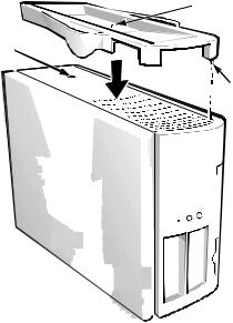
orientation. Although you can attach (and remove) the floor stand at any time with a minimum of system disruption, it is easiest to attach before you set up your computer and connect the back panel cables.
Attach the floor stand as follows:
1.Turn the computer onto its right side so that the drive bays are at the bottom.
2.Fit the floor stand onto what was the left side of the computer.
Position the floor stand as shown in Figure 1-1. Align the large round hole in the floor stand with the securing button on the side of the cover, and align the captive thumbscrew in the stand with the screw hole in the cover.
captive screw
securing button
locator pin
Figure 1-1. Attaching the Floor Stand
As you lower the stand into place, make sure the locator pin (see Figure 1-1) heads into the corner hole of the hole pattern as shown. When the stand is in place, tighten the thumbscrew.
3.Rotate the computer so that the floor stand is at the bottom and the drives are at the top.
To remove the floor stand, turn the computer over so the floor stand is at the top, loosen the screw and lift the floor
stand away, and place the computer in a horizontal position.
Front Panel
Your computer’s front panel contains the following indicators and controls (see Figure 1-2):
•The power button provides control of the system’s alternating current (AC) input power. The push-button switch operates as follows:
—When the computer is turned off, pressing the button turns the computer on.
—When the computer is turned on, pressing the button turns the computer off. However, a lowvoltage (standby) current is maintained from the power supply to the switch. To completely remove all power from the system, unplug the AC power cable from its source.
For systems running Microsoft Windows 95 or Windows NT with the Dell AutoShutdown service operational, pressing the power button causes the system to perform an orderly operating system shutdown before turning off. (For more information, see “Dell AutoShutdown Service” in Chapter 2.)
NOTE: A Display Power Management Signaling (DPMS) monitor does not begin warming up until the computer to which it is attached is turned on.
Thus, some DPMS monitors may not display a video image until several seconds after you turn on your computer.
•The green power indicator lights up when the computer is receiving power.
•The hard-disk drive access indicator lights up when a hard-disk drive is in use. (Drive access indicators for diskette drives and tape drives are located on the front of the drives.)
•The reset button reboots (restarts) your system without your having to turn the power off and then on again. Rebooting the system in this manner reduces stress on system components.
1-4 Dell OptiPlex GXpro Systems User’s Guide

power button 
power indicator
reset button
hard-disk drive access indicator
Figure 1-2. Front Panel
Back Panel
Your computer’s back panel contains various ports and connectors for attaching external devices and includes a security cable slot. These features are described in the following subsections.
Connecting External Devices
You can connect various external devices, such as a mouse and printer, to the input/output (I/O) ports and connectors on the computer’s back panel. The system BIOS detects the presence of most external devices when you boot or reboot your system. When connecting external devices to your computer, follow these guidelines:
•Check the documentation that accompanied the device for specific installation and configuration instructions.
For example, most devices must be connected to a particular I/O port or connector to operate properly. Also, external devices like a mouse or printer usually require you to load software files called device drivers into system memory before they will work. These software drivers help the computer recognize the external device and direct its operation.
Always attach external devices while your computer is turned off. Then turn the computer on before turning on any external devices, unless the documentation for the device specifies otherwise. (If the computer does not seem to recognize the device, try turning on the device before turning on the computer.)
CAUTION: When disconnecting external devices from the back of the computer, wait five seconds after turning off the computer before you disconnect the device to avoid possible damage to the system board.
For information about enabling, disabling, or configuring I/O ports and connectors, see Chapter 3, “Using the System Setup Program.” For detailed descriptions and illustrations of each port and connector on the back panel, see “I/O Ports and Connectors” in Appendix B.
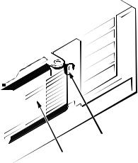
Security Cable Slot
To the right of the fan vent on the back of the computer is a security cable slot (see Figure 1-3) for attaching a commercially available antitheft device. Antitheft devices for personal computers usually include a segment of galvanized cable with an attached locking device and associated key. To prevent unauthorized removal of your computer, loop the cable around an immovable object, insert the locking device into the security cable slot on the back of your computer, and lock the device with its associated key. Complete instructions for installing this kind of antitheft device are usually included with the device.
NOTE: Antitheft devices are of differing designs. Before purchasing such a device, make sure it will work with the cable slot on your computer.
Introduction 1-5
Getting Help
If at any time you don’t understand a procedure described in this guide, or if your system does not perform as expected, Dell provides a number of tools to help you. For more information on these help tools, see the chapter titled “Getting Help” in your Diagnostics and Troubleshooting Guide.
cable slot
fan vent
Figure 1-3. Security Cable Slot
1-6 Dell OptiPlex GXpro Systems User’s Guide

Chapter 2
Using the Software Support Utilities
Your Dell system comes with software support utilities on diskette or on your computer’s hard-disk drive. These software support utilities include system utilities, system services, and bus-mastering integrated drive electronics (IDE) drivers, all of which are documented in this chapter.
NOTE: For information on the additional software support utilities you receive with your system, refer to the following places:
•Video drivers—see the documentation from the
video card manufacturer. (Video drivers support the video graphics requirements of a variety of monitors and application programs running Microsoft Win-
dows NT 3.51 or 4.0, Microsoft Windows 95, Microsoft Windows 3.x, or MS-DOS® operating systems.)
•Audio drivers—see Chapter 6, “Using the Integrated Audio Controller,” of this guide.
•Network interface drivers—see Chapter 5, “Using the Network Interface Controller,” of this guide.
System utilities and services can be used to safeguard your system and to explicitly control certain hardware features. Refer to “System Utilities and Services” found later in this chapter for information about these utilities.
Bus-mastering IDE drivers are provided for the Microsoft Windows 95, Windows NT 3.51, and OS/2® operating systems.
NOTE: Bus-Mastering IDE drivers are not yet available for use with the Windows NT 4.0 operating system.
These drivers can off-load certain functions from the system microprocessor, providing a performance improvement during multithreaded operations (instances where several application programs are running simultaneously). Refer to “Bus-Mastering IDE Drivers” found later in this chapter for information about these utilities.
NOTE: On each software support diskette set you receive, a readme.txt file may be included (on diskette 1 of the set) along with the software utilities or drivers. If included, the readme.txt file contains the latest updates to the information in this manual. Use the editor included with your operating system to view and/or print the contents of readme.txt files.
Software Support Utilities on Diskette
If software support diskettes are included with your Dell system, the Dell system utilities and bus-mastering IDE drivers are provided on these diskettes. To use one of these utilities or drivers, you must install the utility or driver as described later in this chapter.
Dell-Installed Software Support
Utilities
If no software support diskettes were shipped to you, the system utilities and bus-mastering IDE drivers are already installed on your hard-disk drive in two different forms: as working utilities, operative immediately, and as diskette images.
In case you later need to reinstall the files for any reason, you need to copy the diskette images to a backup diskette (see the next section, “Backing Up the Software Support Utilities”). From the backup diskette, you can install the desired file(s) to a directory on your hard-disk drive. Further instructions for installing the utilities and services are provided later in this chapter.
Using the Software Support Utilities |
2-1 |
Backing Up the Software Support
Utilities
Dell recommends that you create original diskette copies, or program diskette sets, of your Dell-installed software. You will need these diskettes if you ever want to reconfigure or reinstall your Dell-installed software. To create program diskettes, use the Dell DiskMaker program to create program diskette sets (available through the Dell Accessories program group or folder).
System Utilities and Services
The following utilities and services are included on your
Dell System Utilities diskette:
•The Asset Tag utility lets you enter a system asset tag number into nonvolatile random-access memory (NVRAM). Thereafter, you can display this number using the Asset Tag utility or the System Setup program.
•The Auto Power On utility enables you to create a batch file to carry out a series of commands when your system is powered on by the Auto Power On feature or by the power button.
•The Dell AutoShutdown service enhances the operation of the power button by providing for an orderly operating system shutdown when the computer system is turned off.
•The Dell Thermal Shutdown service provides mechanisms for protecting the microprocessor against overheating.
Asset Tag Utility
The Asset Tag utility allows you to enter an asset tag number for your computer. The default System Setup screens (see Figure 3-1) do not show the asset tag number unless you enter one using this utility.
NOTE: The Asset Tag utility works only on systems running MS-DOS and Windows 95.
Installing the Asset Tag Utility
The Asset Tag Utility is already installed on your harddisk drive. If you need to reinstall the Asset Tag Utility, perform the following steps:
1.If you have not already done so, use the Dell DiskMaker to make a diskette copy of the Dell System Utilities diskette image on your hard-disk drive.
The Dell DiskMaker is available through the Dell Accessories program group. For more information, refer to the online help provided in the Dell DiskMaker program.
2.With the backup diskette in drive A, copy the asset.com file from the diskette to the directory of your choice on your hard-disk drive.
If the path statement in your autoexec.bat file does not already contain the directory in which you reinstalled the Asset Tag utility, modify the path statement to include that directory. (See your MS-DOS reference documentation for information on modifying the autoexec.bat file.)
Using the Asset Tag Utility
After you reinstall the Asset Tag utility, you can use it to enter an asset tag number that you or your company assign to your computer; you can also use it to reenter the computer’s service tag number if that becomes necessary.
Use the asset command from the system prompt. To view existing asset tag and service tag numbers, type asset and
press <ENTER>. (You can also view the asset tag number using the System Setup program described in Chapter 3.)
Assigning and Deleting an Asset Tag Number
An asset tag number can have up to ten characters; any combination of characters excluding spaces is valid. To assign or change an asset tag number, type asset and a space followed by the new number; then press <ENTER>. For example, type the following command line and press <ENTER>:
asset 1234567890
When prompted to verify the asset tag number, type y and press <ENTER>. The system then displays the new or modified asset tag number and the service tag number.
To delete the asset tag number without assigning a new one, type asset /d and press <ENTER>.
2-2 Dell OptiPlex GXpro Systems User’s Guide
Loading...