


 Loading...
Copyright © 2004 - 2006 EqualLogic, Inc.
September 2006
EqualLogic is a registered trademark of EqualLogic, Inc.
All trademarks and registered trademarks mentioned herein are the property of their respective owners.
Possession, use, or copying of the documentation or the software described in this publication is authorized only under the license agreement.
EqualLogic, Inc. will not be held liable for technical or editorial errors or omissions contained herein. Information in this document is subject to change.
Part Number: 110-0003-R6
ii

Table of Contents
Preface .................................................................................................................. |
v |
Audience .......................................................................................................... |
v |
Organization ................................................................................................... |
vi |
Conventions .................................................................................................... |
vi |
Documentation and Technical Support ......................................................... |
vii |
Warranty Information .................................................................................. |
viii |
Restricted Access Requirement ................................................................... |
viii |
Regulatory Agency Notice and Notes ......................................................... |
viii |
1 Basic Array Information............................................................................... |
1-1 |
Front and Back Panels.................................................................................. |
1-1 |
Interpreting LEDs......................................................................................... |
1-2 |
Using an Electrostatic Wrist Strap ............................................................... |
1-5 |
Shutting Down and Restarting an Array ...................................................... |
1-6 |
2 Maintaining Disks.......................................................................................... |
2-1 |
Disk Handling Requirements ....................................................................... |
2-1 |
Identifying Failed Disks ............................................................................... |
2-2 |
Removing Disks ........................................................................................... |
2-2 |
Installing Disks............................................................................................. |
2-3 |
3 Maintaining Control Modules ...................................................................... |
3-1 |
Control Module Handling Requirements ..................................................... |
3-1 |
Identifying Control Module Failures............................................................ |
3-2 |
Understanding Failover Behavior ................................................................ |
3-2 |
Maintaining Control Module Firmware ....................................................... |
3-3 |
Connecting Network Cables......................................................................... |
3-4 |
Installing a Control Module ......................................................................... |
3-7 |
Removing a Control Module........................................................................ |
3-9 |
Replacing the Compact Flash Card ............................................................ |
3-11 |
Replacing the Cache Battery ...................................................................... |
3-12 |
Replacing the NVRAM Coin Cell Battery................................................. |
3-15 |
4 Maintaining Power Supplies......................................................................... |
4-1 |
Identifying Power Supply Failures............................................................... |
4-1 |
Identifying the Power Supply Model ........................................................... |
4-1 |
Removing a Power Supply ........................................................................... |
4-2 |
Installing a Power Supply............................................................................. |
4-3 |
iii
PS Series 50E to 400E Hardware Maintenance |
Table of Contents |
5 Maintaining Fan Trays.................................................................................. |
5-1 |
Identifying Fan Tray Failures....................................................................... |
5-1 |
Removing a Fan Tray ................................................................................... |
5-1 |
Installing a Fan Tray..................................................................................... |
5-2 |
A Environmental, Power, and Physical Requirements ................................. |
A-1 |
B Control Module Models................................................................................ |
B-1 |
Model Face Plates ........................................................................................ |
B-1 |
Model Differences........................................................................................ |
B-2 |
Setting Up a Serial Connection .................................................................... |
B-2 |
Index............................................................................................................ |
Index-1 |
iv

Preface
This manual describes how to maintain the hardware for EqualLogic PS Series 50E to 400E storage arrays. Each array contains hot-swappable fans and power supplies, up to fourteen RAID-protected disks, and single or dual hot-swappable control modules, each with three Gigabit Ethernet interfaces.
With one or more PS Series storage arrays, you can create a PS Series group—a self-managing, iSCSI storage area network (SAN) that is affordable and easy to use, regardless of scale. To install the array hardware and set up a group, see the PS Series 50E to 400E QuickStart.
Note: For PS Series 50E to 400E storage arrays, PS Series Firmware Version 2.2 and higher firmware versions support the Type II control module, which can be identified by a blue face plate and single serial port. The figures in this manual show arrays installed with Type II control modules. However—unless otherwise noted—the information herein also applies to the functionally equivalent Type I control module, which can be identified by a dark gray face plate and two serial ports.
Do not mix different control module models in an array. However, a PS Series group can include arrays with Type II control modules and
arrays with Type I control modules, if all the arrays are running compatible firmware, as described in the PS Series Release Notes.
Audience
This manual is designed for the administrators responsible for maintaining
PS Series 50E to 400E storage array hardware. Administrators are not required to have extensive network or storage system experience. However, it is useful to understand:
•Basic networking concepts
•Current network environment
•User disk storage requirements
•Disk storage management
•RAID configurations
Note: Although this manual provides examples of using PS Series storage arrays in some common network configurations, detailed information about setting up a network is beyond its scope.
v

PS Series 50E to 400E Hardware Maintenance |
Preface |
Organization
This manual is organized as follows:
•Chapter 1, Basic Array Information, describes the PS Series storage array front and back panels, how to interpret LEDs, how to use an electrostatic wrist strap, and how to shut down and restart an array.
•Chapter 2, Maintaining Disks, describes how to install and remove disks.
•Chapter 3, Maintaining Control Modules, describes how to install and maintain control modules and replace the cache battery, NVRAM coin cell battery, and compact flash card. It also describes the best way to connect network cables to control modules for high performance and availability.
•Chapter 5, Maintaining Fan Trays, describes how to install and remove fan trays in an array.
•Chapter 4, Maintaining Power Supplies, describes how to determine the type of power supply and how to install and remove a power supply in an array.
•Appendix A, Environmental, Power, and Physical Requirements, describes the requirements for an array.
•Appendix B, Control Module Models, explains the differences between a Type I control module and a Type II control module.
Conventions
Conventions used in the manual are shown in the following table.
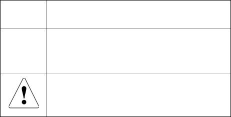
Convention Usage
When displayed, indicates that you must attach an electrostatic wrist strap to your wrist and a grounded device to prevent electrostatic discharge.
When displayed, indicates a potential personal injury hazard.
vi
PS Series 50E to 400E Hardware Maintenance |
Preface |
Documentation and Technical Support
For detailed information about PS Series storage arrays, groups, and volumes, see the following documentation:
•Release Notes. Provides the latest information about PS Series storage arrays.
•QuickStart. Describes how to set up PS Series 50E to 400E storage array hardware and create a PS Series group.
•Group Administration. Describes how to use the Group Manager graphical user interface (GUI) to manage a PS Series group. This manual provides comprehensive information about product concepts and procedures.
•CLI Reference. Describes how to use the Group Manager command line interface (CLI) to manage a PS Series group and individual arrays.
•Hardware Maintenance. Provides information about maintaining PS Series 50E to 400E storage array hardware.
The QuickStart and Hardware Maintenance manuals are printed and shipped with the product. They are also located on the documentation CD-ROM that is shipped with the product, along with the Group Administration and CLI Reference manuals and the Group Manager online help.
In addition, the Host Integration Tools for Windows® systems are available on the EqualLogic website and on a CD-ROM that is shipped with the product.
Technical support on EqualLogic products is available for customers with arrays under warranty and customers with a valid support contract. You can obtain technical support in the following ways:
•Visit the EqualLogic Customer Support website to download the latest documentation and firmware. Go to www.equallogic.com and log in to your customer support account. If you do not have an account, create one.
•In the United States, call 877-887-7337. International customers should call +00 1 919-767-5729. If the issue is urgent, ask to speak with a member of the EqualLogic Customer Support team.
•From the EqualLogic Customer Support website, you can submit a service request.
•Send e-mail to support@equallogic.com and clearly describe the issue or problem.
vii
PS Series 50E to 400E Hardware Maintenance |
Preface |
Warranty Information
The PS Series storage array warranty is included in the shipping box. For information about registering a warranty, visit the EqualLogic website,
www.equallogic.com.
Restricted Access Requirement
PS Series storage arrays must be installed in a restricted access location, which is an area that is intended only for qualified or trained personnel.
Regulatory Agency Notice and Notes
PS Series storage arrays have been tested and found to comply with the limits for a Class A digital device, pursuant to part 15 of the FCC rules and other international standards. These limits are designed to provide reasonable protection against harmful interference when the equipment is operated in a commercial environment.
This equipment generates, uses, and can radiate radio frequency energy and, if not installed and used in accordance with the instruction manual, may cause harmful interference to radio communications. Operation of this equipment in a residential area is likely to cause harmful interference, which the user will be required to correct at their own expense.
Regulatory Notes
Service Note A PS Series storage array has more than one power supply cord. Disconnect both power supply cords before servicing to avoid electric shock.
Warning When an approved SFP (small form factor pluggable) optical network connector is installed, a PS Series storage array is a Class 1 laser product. Using an unapproved SFP may void some safety certifications. See your PS Series array service provider for a list of approved SFPs, or purchase an SFP from EqualLogic.
There is a danger of explosion if a PS Series storage array control module cache battery is incorrectly replaced. Replace a battery only with the same or equivalent battery, as recommended by the manufacturer, and use the instructions in this document. Discard used batteries according to the manufacturer’s instructions.
viii

1 Basic Array Information
Basic information about PS Series 50E to 400E storage arrays include:
•Front and Back Panels on page 1-1
•Interpreting LEDs on page 1-2
•Using an Electrostatic Wrist Strap on page 1-5
•Shutting Down and Restarting an Array on page 1-6
Front and Back Panels
The front and back panels of a PS Series storage array are shown below.
Figure 1-1: PS Series 50E to 400E Storage Array Front Panel
Figure 1-2: PS Series 50E to 400E Storage Array Back Panel
1–1

PS Series 50E to 400E Hardware Maintenance |
Basic Array Information |
Note: The figures in this manual show Type II control modules (blue face plate), which are functionally equivalent to Type I control modules (dark gray face plate). See Appendix B, Control Module Models, for information.
Figure 1-3: Type II Control Module Details
Interpreting LEDs
The following figures and tables describe PS Series 50E to 400E storage array LEDs, which can alert you to errors and conditions that require your attention. Report serious errors to your PS Series array service provider.
Figure 1-4: Front Panel LEDs
Table 1-1: Front Panel LED Descriptions
Disk LEDs |
Color |
Description |
|
|
|
Left |
Off |
No power or error condition. |
|
|
|
|
Green |
Power. |
|
|
|
Right |
Off |
No power or normal condition. |
|
|
|
|
Red |
Error condition. |
|
|
|
|
Flashing green |
Disk activity. |
|
|
|
1–2
PS Series 50E to 400E Hardware Maintenance Basic Array Information
Table 1-1: Front Panel LED Descriptions (Continued)
Array LEDs |
Color |
Description |
|
|
|
PWR |
Off |
No power. |
|
Green |
Power. |
|
|
|
WARN |
Off |
No power or normal condition. |
|
Red |
One or more of the following has occurred: |
|
|
• RAIDset is degraded but still functioning. |
|
|
• RAIDset (volume) has lost blocks. |
|
|
• Temperature of a component is near upper limit. |
|
|
• Fan tray fan RPMs exceed upper or lower limit. |
|
|
• Power supply fan has failed. |
|
|
• Power supply is not installed or has no power. |
|
|
• Only one functioning control module. |
|
|
• Lock on secondary control module is open. |
|
|
• Active control module is syncing with secondary. |
|
|
• No communication between control modules. |
|
|
• No replication progress for 1 hour or more. |
|
|
• Installed spare disk does not have enough |
|
|
capacity to replace a disk in a RAIDset. |
|
|
• A non-critical hardware component has failed. |
|
|
|
ALRM |
Off |
No power or normal condition. |
|
Red |
One or more of the following has occurred: |
|
|
• RAIDset is not functioning. |
|
|
• Lost block table is full. |
|
|
• Array temperature exceeds upper limit. |
|
|
• Control module cache has lost data. |
|
|
• One or both fan trays are not installed. |
|
|
• Both fans on a fan tray have failed. |
|
|
• Cache battery has less than 72 hours of charge. |
|
|
• NVRAM coin cell battery has failed. |
|
|
• Cache contains data that does not belong to any |
|
|
of the installed disks. |
|
|
• More than one valid RAIDset exists in the array. |
|
|
• Control modules are different models. |
|
|
• A critical hardware component has failed. |
|
|
|
1–3

PS Series 50E to 400E Hardware Maintenance |
Basic Array Information |
Figure 1-5: Back Panel LEDs
Table 1-2: Back Panel LED Descriptions
Control Module LEDs |
Color |
Description |
|
|
|
PWR |
Off |
No power. |
|
Green |
Power. |
|
|
|
ERR |
Off |
No power or no error condition. |
|
Red |
Array is starting up or error condition. |
|
|
|
ACT |
Off |
No power. |
|
|
Secondary control module (only Type I). |
|
|
Secondary control module is not |
|
|
synchronized with active control module |
|
|
or error condition (only Type II). |
|
Green |
Active control module (serving network I/O). |
|
|
|
|
Orange |
Secondary control module is synchronized |
|
|
with active (only Type II). |
Network Interface LEDs |
Color |
Description |
|
|
|
LNK |
Off |
No power or not connected to network. |
|
Green |
Connected to network switch. |
|
|
|
TX |
Off |
No power or not transmitting. |
|
Green |
Transmitting. |
|
|
|
1–4
PS Series 50E to 400E Hardware Maintenance Basic Array Information
Table 1-2: Back Panel LEDs (Continued)
Fan Tray LED |
Color |
Description |
|
|
|
|
|
Outside edge of fan tray |
Off |
No power. |
|
|
|
|
|
|
Green |
Environmental Management Module (EMM) |
|
|
|
and fans on the fan tray are functioning. |
|
|
Red |
EMM or a fan on the fan tray has failed. |
|
|
|
The LED will be temporarily red when the |
|
|
|
array is first powered on or when the fan tray |
|
|
|
is installed. |
|
|
Flashing |
Fan RPMs exceed upper or lower limit. |
|
|
red |
|
|
Power Supply LEDs |
Color |
Description |
|
|
|
|
|
Left (LED location may |
Off |
No power or error condition. |
|
differ on some models) |
|
|
|
Orange |
Input power good (AC). |
||
|
|||
|
|
|
|
Right (LED location may |
Off |
No power or error condition. |
|
differ on some models) |
|
|
|
Green |
Output power good (DC). |
||
|
|||
|
|
|
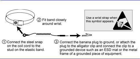
Using an Electrostatic Wrist Strap
When handling the storage array chassis, disks, or control modules, you must use an electrostatic protection device to prevent electrostatic discharge.
An electrostatic wrist strap is included in the shipping box.
Figure 1-6: Using an Electrostatic Wrist Strap
1–5

PS Series 50E to 400E Hardware Maintenance |
Basic Array Information |
Shutting Down and Restarting an Array
PS Series 50E to 400E storage arrays include redundant, hot-swappable disks, fan trays, power supplies, and control modules (if a dual control module array). You can remove a redundant component without affecting operation if a functioning component is available. Otherwise, it is recommended that you cleanly shut down the array and turn off power before removing a component.
Note: When an array is shut down, any volumes with data on the array will be set offline until the array is successfully restarted. This may affect initiators connected to the volumes.
To shut down an array, follow these steps:
1.Do one of the following:
–Use telnet or SSH to connect to a functioning IP address assigned to a network interface on the array. Do not connect to the group IP address.
–Use the null modem cable shipped with the array to connect Serial Port 0 on the active control module (LED labeled ACT is green) to a console or a computer running a terminal emulator. See Appendix B, Setting Up a Serial Connection for more information.
2.Log in to an account with read-write access, such as the grpadmin account.
3.Enter the shutdown command, as shown next.
Login: grpadmin
Password: xxxxxxx
Welcome to Group Manager Copyright 2001-2006 EqualLogic, Inc.
> shutdown
If you are using a serial connection to shut down an array, it is safe to turn off power when the “press any key” message appears. (Pressing any key will restart both control modules.)
If you are using a network connection, the session will be disconnected before the array is fully shut down. Confirm that the ACT LED on each control module is off (not lit) before turning off power to the array.
After performing array maintenance, you can turn on power to the array. When the array restart completes, the member and volumes will be set online.
1–6

2 Maintaining Disks
PS Series 50E to 400E storage arrays include up to 14 hot-swappable disks. Disk maintenance topics include:
•Disk Handling Requirements on page 2-1
•Identifying Failed Disks on page 2-2
•Removing Disks on page 2-2
•Installing Disks on page 2-3
Disk Handling Requirements
You must adhere to the following disk handling requirements:
•Store disks properly. When not installed in an array, store a disk in the antistatic bag and foam insert in which the disk was shipped. Do not stack disks or place anything on top of a disk.
•Protect disks from electrostatic discharge. Wear an electrostatic wrist strap when handling a disk, unless it is in an antistatic bag.
•Handle disks carefully. Hold a disk only by the sides of the plastic carrier or by the handle. Do not drop or jolt a disk or force a disk into an array disk slot.
•Warm disks to room temperature before installation. For example, let disks sit overnight before installing them in an array.
•Install disks after rack mounting the array. Do not install disks until the array is completely mounted in its final location. The array must not be moved once disks are installed.
•Do not leave disk slots empty. Each disk slot in an array must contain a disk drive assembly or a blank carrier. Operating an array with an empty disk slot will void your warranty and support contract.
•Do not remove a disk from its plastic carrier. This action will void your warranty and support contract.
•Keep shipping material for servicing. To obtain service for a disk, it must be returned in the antistatic bag and foam insert in which the disk was shipped. Shipping disks in unauthorized packaging may void your warranty. Obtain authorized packaging from your PS Series array service provider.
2–1
PS Series 50E to 400E Hardware Maintenance |
Maintaining Disks |
Identifying Failed Disks
Disks in PS Series 50E to 400E storage arrays are installed in slots numbered from 0 to 13 (from left to right). A disk failure is indicated by:
•The disk’s right LED is red and the left LED is off. See Interpreting LEDs on page 1-2.
•A message on the console, in the event log, or in the Group Manager GUI Alarms panel describes a disk failure.
•The GUI Member Disks window or the CLI member select show disks command shows a disk failure.
Handling Failed Disks
How an array handles a disk failure depends on whether a spare disk is available and whether the RAIDset containing the failed disk is degraded. For example:
•If a spare disk is available, it replaces the failed disk. Performance is normal.
•If a spare disk is not available and the failed disk is in a RAIDset with no previous disk failure, the RAIDset becomes degraded. Performance may be slightly impaired.
•If a spare disk is not available and the failed disk is in a RAIDset that is already degraded, data may be lost and must be recovered from a backup.
Removing Disks
Before removing a disk or blank carrier from an array, attach an electrostatic protection device, as described in Using an Electrostatic Wrist Strap on page 1-5.
Notes: Replace a failed disk as soon as possible to ensure the highest availability.
Do not remove a disk from a slot, unless you have another disk or a blank carrier to replace it. Each slot must contain a disk or blank carrier.
Do not remove a functioning disk from an array, unless the disk is a spare. If you remove a spare, replace the disk as soon as possible.
Before removing a disk, allow the disk to stop spinning and the heads to land. To do this, press and hold the disk locking latch. Then, pull out the handle and wait 10 seconds before removing the disk from the slot.
After removing a disk, store it in the antistatic bag and foam insert in which it was shipped.
2–2
Loading...