


 Loading...
Alienware Area-51
Service Manual
Computer Model: Alienware Area-51 R2
Regulatory Model: D03X
Regulatory Type: D03X001
Notes, Cautions, and Warnings
NOTE: A NOTE indicates important information that helps you make better use of your computer.
CAUTION: A CAUTION indicates either potential damage to hardware or loss of data and tells you how to avoid the problem.
WARNING: A WARNING indicates a potential for property damage, personal injury, or death.
Copyright © 2014 Dell Inc. All rights reserved. This product is protected by U.S. and international copyright and intellectual property laws. Dell™ and the Dell logo are trademarks of Dell Inc. in the United States and/or other jurisdictions. All other marks and names mentioned herein may be trademarks of their respective companies.
2014 - 10
Rev. A00
Contents |
|
Before Working Inside Your Computer |
...................... 10 |
Before You Begin .............................................................................................. |
10 |
Safety Instructions............................................................................................ |
10 |
Recommended Tools......................................................................................... |
12 |
After Working Inside Your Computer.......................... |
13 |
Technical Overview.............................................................. |
14 |
Inside View of Your Computer........................................................................... |
14 |
Right View.................................................................................................... |
15 |
Left View....................................................................................................... |
16 |
System-Board Components............................................................................... |
17 |
I/O Board Components...................................................................................... |
18 |
Lifting the Computer.......................................................... |
20 |
Procedure.......................................................................................................... |
20 |
Removing the Stability Foot........................................... |
22 |
Procedure.......................................................................................................... |
22 |
Replacing the Stability Foot........................................... |
25 |
Procedure.......................................................................................................... |
25 |
Removing the Side Panels............................................... |
26 |
Procedure.......................................................................................................... |
26 |
Replacing the Side Panels............................................... |
28 |
Procedure.......................................................................................................... |
28 |
Removing the Battery....................................................... |
29 |
Prerequisites..................................................................................................... |
29 |
Procedure.......................................................................................................... |
30 |
Replacing the Battery......................................................... |
31 |
Procedure........................................................................................................... |
31 |
Post-requisites.................................................................................................. |
32 |
Removing the Battery Case............................................ |
33 |
Prerequisites..................................................................................................... |
33 |
Procedure.......................................................................................................... |
33 |
Replacing the Battery Case............................................ |
36 |
Procedure.......................................................................................................... |
36 |
Post-requisites.................................................................................................. |
36 |
Removing the Hard Drive................................................. |
37 |
Prerequisites..................................................................................................... |
37 |
Procedure.......................................................................................................... |
37 |
Replacing the Hard Drive................................................. |
40 |
Procedure.......................................................................................................... |
40 |
Post-requisites................................................................................................. |
40 |
Removing the Optical Drive............................................. |
41 |
Prerequisites...................................................................................................... |
41 |
Procedure........................................................................................................... |
41 |
Replacing the Optical Drive............................................ |
44 |
Procedure.......................................................................................................... |
44 |
Post-requisites.................................................................................................. |
44 |
Removing the Right AlienFX Side-Panel |
|
Connector................................................................................ |
45 |
Prerequisites..................................................................................................... |
45 |
Procedure.......................................................................................................... |
45 |
Replacing the Right AlienFX Side-Panel |
|
Connector................................................................................ |
48 |
Procedure.......................................................................................................... |
48 |
Post-requisites................................................................................................. |
48 |
Removing the Left AlienFX Side-Panel |
|
Connector................................................................................ |
49 |
Prerequisites..................................................................................................... |
49 |
Procedure.......................................................................................................... |
49 |
Replacing the Left AlienFX Side-Panel |
|
Connector................................................................................ |
53 |
Procedure.......................................................................................................... |
53 |
Post-requisites.................................................................................................. |
53 |
Removing the I/O Board.................................................... |
54 |
Prerequisites..................................................................................................... |
54 |
Procedure.......................................................................................................... |
54 |
Replacing the I/O Board..................................................... |
57 |
Procedure.......................................................................................................... |
57 |
Post-requisites.................................................................................................. |
57 |
Removing the Drive-Bay Heat-Sensor....................... |
58 |
Prerequisites..................................................................................................... |
58 |
Procedure.......................................................................................................... |
58 |
Replacing the Drive-Bay Heat-Sensor........................ |
61 |
Procedure........................................................................................................... |
61 |
Post-requisites.................................................................................................. |
61 |
Removing the Memory Module(s)............................... |
62 |
Prerequisites..................................................................................................... |
62 |
Procedure.......................................................................................................... |
62 |
Replacing the Memory Module(s)................................ |
64 |
Procedure.......................................................................................................... |
64 |
Post-requisites.................................................................................................. |
65 |
Removing the Graphics Card.......................................... |
66 |
Prerequisites..................................................................................................... |
66 |
Procedure.......................................................................................................... |
66 |
Replacing the Graphics Card.......................................... |
69 |
Procedure.......................................................................................................... |
69 |
Post-requisites.................................................................................................. |
69 |
Removing the Multiple Graphics Cards..................... |
70 |
Prerequisites..................................................................................................... |
70 |
Procedure.......................................................................................................... |
70 |
Replacing the Multiple Graphics Cards...................... |
74 |
Procedure.......................................................................................................... |
74 |
Post-requisites.................................................................................................. |
74 |
Removing the Full-length Graphics Cards................ |
75 |
Prerequisites..................................................................................................... |
75 |
Procedure.......................................................................................................... |
75 |
Replacing the Full-length Graphics Cards................ |
79 |
Procedure.......................................................................................................... |
79 |
Post-requisites.................................................................................................. |
79 |
Removing the PCI Fan........................................................ |
80 |
Prerequisites.................................................................................................... |
80 |
Procedure.......................................................................................................... |
80 |
Replacing the PCI Fan........................................................ |
85 |
Procedure.......................................................................................................... |
85 |
Post-requisites................................................................................................. |
85 |
Removing the Front-bezel Heat-sensor................... |
86 |
Prerequisites..................................................................................................... |
86 |
Procedure.......................................................................................................... |
86 |
Replacing the Front-bezel Heat-sensor................... |
88 |
Procedure.......................................................................................................... |
88 |
Post-requisites................................................................................................. |
88 |
Removing the Memory Fan............................................. |
89 |
Prerequisites..................................................................................................... |
89 |
Procedure.......................................................................................................... |
89 |
Replacing the Memory Fan.............................................. |
91 |
Procedure........................................................................................................... |
91 |
Post-requisites.................................................................................................. |
91 |
Removing the Processor Cooling-Assembly.......... |
92 |
Prerequisites..................................................................................................... |
92 |
Procedure.......................................................................................................... |
92 |
Replacing the Processor Cooling Assembly |
........... 95 |
Procedure.......................................................................................................... |
95 |
Post-requisites.................................................................................................. |
96 |
Removing the Processor.................................................. |
97 |
Prerequisites..................................................................................................... |
97 |
Procedure.......................................................................................................... |
97 |
Replacing the Processor.................................................. |
99 |
Procedure.......................................................................................................... |
99 |
Post-requisites................................................................................................ |
100 |
Removing the Power-Supply Unit............................... |
101 |
Prerequisites.................................................................................................... |
101 |
Procedure......................................................................................................... |
101 |
Replacing the Power-Supply Unit.............................. |
104 |
Procedure........................................................................................................ |
105 |
Post-requisites................................................................................................ |
106 |
Removing the Coin-Cell Battery.................................. |
107 |
Prerequisites.................................................................................................... |
107 |
Procedure......................................................................................................... |
107 |
Replacing the Coin-Cell Battery.................................. |
109 |
Procedure........................................................................................................ |
109 |
Post-requisites................................................................................................ |
109 |
Removing the Wireless Card......................................... |
110 |
Prerequisites.................................................................................................... |
110 |
Procedure......................................................................................................... |
110 |
Replacing the Wireless Card.......................................... |
112 |
Procedure......................................................................................................... |
112 |
Post-requisites................................................................................................. |
112 |
Removing the Logo Board.............................................. |
113 |
Prerequisites.................................................................................................... |
113 |
Procedure......................................................................................................... |
113 |
Replacing the Logo Board............................................... |
116 |
Procedure......................................................................................................... |
116 |
Post-requisites................................................................................................. |
116 |
Removing the System Board......................................... |
117 |
Prerequisites..................................................................................................... |
117 |
Procedure......................................................................................................... |
118 |
Replacing the System Board......................................... |
119 |
Procedure......................................................................................................... |
119 |
Post-requisites................................................................................................. |
119 |
System Setup........................................................................ |
121 |
Overview .......................................................................................................... |
121 |
Entering System Setup ................................................................................... |
121 |
System Setup Options..................................................................................... |
121 |
Clearing Forgotten Passwords........................................................................ |
130 |
Clearing CMOS Settings................................................................................... |
131 |
Flashing the BIOS............................................................................................ |
132 |

Before Working Inside Your
Computer
CAUTION: To avoid damaging the components and cards, handle them by their edges and avoid touching pins and contacts.
NOTE: The images in this document may differ from your computer depending on the configuration you ordered.
Before You Begin
1Save and close all open files and exit all open applications.
2Shut down your computer.
–Windows 8.1: On the Start screen, click or tap the power icon  →
→
Shut down.
–Windows 7: Click or tap Start → Shut down.
NOTE: If you are using a different operating system, see the documentation of your operating system for shut-down instructions.
3Disconnect your computer and all attached devices from their electrical outlets.
4Disconnect all cables such as telephone cables, network cables and so on, from your computer.
5Disconnect all attached devices and peripherals, such as keyboard, mouse, monitor, and so on, from your computer.
6Remove any media card and optical disc from your computer, if applicable.
7After the computer is unplugged, press and hold the power button for 5 seconds to ground the system board.
Safety Instructions
Use the following safety guidelines to protect your computer from potential damage and ensure your personal safety.
10
WARNING: Before working inside your computer, read the safety information that shipped with your computer. For more safety best practices, see the Regulatory Compliance home page at dell.com/regulatory_compliance.
WARNING: Disconnect all power sources before opening the computer cover or panels. After you finish working inside the computer, replace all covers, panels, and screws before connecting to the power source.
CAUTION: To avoid damaging the computer, make sure that the work surface is flat and clean.
CAUTION: To avoid damaging the components and cards, handle them by their edges and avoid touching pins and contacts.
CAUTION: Only a certified service technician is authorized to remove the computer cover and access any of the components inside the computer. See the safety instructions for complete information about safety precautions, working inside your computer, and protecting against electrostatic discharge.
CAUTION: Before touching anything inside your computer, ground yourself by touching an unpainted metal surface, such as the metal at the back of the computer. While you work, periodically touch an unpainted metal surface to dissipate static electricity, which could harm internal components.
CAUTION: When you disconnect a cable, pull on its connector or on its pull-tab, not on the cable itself. Some cables have connectors with locking tabs or thumb-screws that you must disengage before disconnecting the cable. When disconnecting cables, keep them evenly aligned to avoid bending any connector pins. When connecting cables, make sure that the ports and connectors are correctly oriented and aligned.
CAUTION: To disconnect a network cable, first unplug the cable from your computer and then unplug the cable from the network device.
11

CAUTION: Press and eject any installed card from the mediacard reader.
Recommended Tools
The procedures in this document may require the following tools:
•Philips screwdriver
•Flat-head screwdriver
•Plastic scribe
12

After Working Inside Your
Computer
CAUTION: Leaving stray or loose screws inside your computer may severely damage your computer.
1Replace all screws and make sure that no stray screws remain inside your computer.
2Connect any external devices, peripherals, and cables you removed before working on your computer.
3Replace any media cards, discs, and any other part(s) that you removed before working on your computer.
4 Connect your computer and all attached devices to their electrical outlets.
5Turn on your computer.
13

Technical Overview
WARNING: Before working inside your computer, read the safety information that shipped with your computer and follow the steps in Before Working Inside Your Computer.
After working inside your computer, follow the instructions in After Working Inside Your Computer. For more safety best practices, see the Regulatory Compliance home page at dell.com/regulatory_compliance.
Inside View of Your Computer
To view the different components installed in your computer. See “Right View” and “Left View”.
14
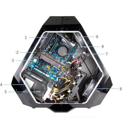
Right View
1 |
processor liquid-cooling |
2 |
graphics card |
|
assembly-fan |
|
|
3 |
system board |
4 |
power-supply |
5 |
AlienFX side-panel connector |
6 |
PCI fan |
7 |
processor liquid-cooling assembly 8 |
memory modules |
|
|
pump |
|
|
9memory fan (top fan)
15

Left View
1 |
optical drive (ODD) |
2 |
I/O board (IO BRD) |
3 |
drive-bay heat-sensor |
4 |
2.5 inch drive bracket (HDD4/ |
|
|
|
HDD5) |
5 |
AlienFX side-panel connector |
6 |
rear I/O accessibility lighting |
|
|
|
batteries |
7 |
3.5 inch drive bracket (HDD1) |
8 |
3.5 inch drive bracket (HDD2) |
93.5 inch drive bracket (HDD3)
16

System-Board Components
1 |
processor liquid cooling-assembly 2 |
audio connector (AUDIO101) |
|
|
fan (LCM_FAN1) |
|
|
3 |
PCI-Express x16 slot (SLOT1) |
4 |
low pin count debug header |
|
|
|
(LPC1) |
5 |
password reset jumper |
6 |
PCI-Express x1 slot (SLOT2) |
|
(PASSWORD1) |
|
|
17

7 |
PCI-Express x16 slot (SLOT3) |
8 |
M.2 connector (wireless card) |
9 |
coin-cell battery socket (BAT1) |
10 |
CMOS reset jumper (CLEAR |
|
|
|
CMOS1) |
11 |
PCI-Express x4 slot (SLOT4) |
12 |
Thunderbolt connector (TBT1) |
13 |
PCI-Express x16 slot (SLOT5) |
14 |
Serial Peripheral Interface |
|
|
|
connector (SP11) |
15 |
PCI-fan connector (SIDE_FAN1) |
16 |
drive-bay heat-sensor |
|
|
|
connector (SENSOR1) |
17 |
chassis heat-sensor connector |
18 |
PCI-Express power connector |
|
(SENSOR2) |
|
(PCIE_PWR1) |
19 |
PCI-Express fan 1 connector |
20 |
SATA drive connectors |
|
(PCI_FAN1) |
|
|
21 |
USB connector (USB1) |
22 |
LED Power Switch (PANEL1) |
23 |
USB connector (USB3_MB1) |
24 |
Advanced Technology xTended |
|
|
|
(ATX) power connector (ATX |
|
|
|
PWR1) |
25 |
processor socket (CPU1) |
26 |
memory-module slot (DIMM3) |
27 |
memory-module slot (DIMM4) |
28 |
processor liquid-cooling |
|
|
|
assembly fan connector |
|
|
|
(MID_FAN1) |
29 |
memory fan connector |
30 |
processor-power connector |
|
(TOP_FAN1) |
|
(CPU PWR1) |
31 |
processor liquid-cooling assembly 32 |
memory-module slot (DIMM2) |
|
|
pump-fan connector |
|
|
|
(PUMP_FAN1) |
|
|
33 |
memory-module slot (DIMM1) |
|
|
I/O Board Components
NOTE: The location of the connectors may vary based on the selections you made at the time of purchase.
18
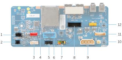
1 |
rear I/O accessibility lighting |
2 |
rear I/O accessibility lighting |
|
battery connector (VBAT1) |
|
connector (PORCH_LIGHT1) |
3 |
left theater-lighting connector |
4 |
right theater-lighting connector |
|
(POGO_IN_L1) |
|
(POGO_IN_R1) |
5 |
USB connector (USB1) |
6 |
debug connector (DEBUG1) |
7 |
front I/O control connector |
8 |
front I/O connector (USB3_FIO1) |
|
(FIO_PWR1) |
|
|
9 |
main-power connector (PWR1) |
10 |
optical drive power connector |
|
|
|
(ODD1) |
11 |
logo board connector (LOGO1) |
12 |
audio connector (AUDIOIO1) |
19

Lifting the Computer
Procedure
1With both hands, hold the handle on top of the computer.
20
2Lift the computer.
1 handle |
2 computer |
21

Removing the Stability Foot
WARNING: Before working inside your computer, read the safety information that shipped with your computer and follow the steps in Before Working Inside Your Computer.
After working inside your computer, follow the instructions in After Working Inside Your Computer. For more safety best practices, see the Regulatory Compliance home page at dell.com/regulatory_compliance.
Procedure
1Tilt the computer towards the front until the base is facing up.
2Remove the screws that secure the stability foot to the computer.
22

3Lift the stability foot off the computer.
1 |
stability foot |
2 screws (2) |
3computer
23

4Tilt the computer back to the upright position.
24

Replacing the Stability Foot
WARNING: Before working inside your computer, read the safety information that shipped with your computer and follow the steps in Before Working Inside Your Computer.
After working inside your computer, follow the instructions in After Working Inside Your Computer. For more safety best practices, see the Regulatory Compliance home page at dell.com/regulatory_compliance.
Procedure
1Tilt the computer towards the front until the base is facing up.
2Align the screw holes on the stability foot with the screw holes on the base of the computer and replace the screws.
3Tilt the computer back to the upright position.
25

Removing the Side Panels
WARNING: Before working inside your computer, read the safety information that shipped with your computer and follow the steps in Before Working Inside Your Computer.
After working inside your computer, follow the instructions in After Working Inside Your Computer. For more safety best practices, see the Regulatory Compliance home page at dell.com/regulatory_compliance.
Procedure
NOTE: Make sure that you remove the security cable from the security cable slot (if applicable).
1Remove the screw that secures the security-cable slot latch. The security-cable slot slides to the unlocked position.
2Lift the release panel to open the right side-panel.
26
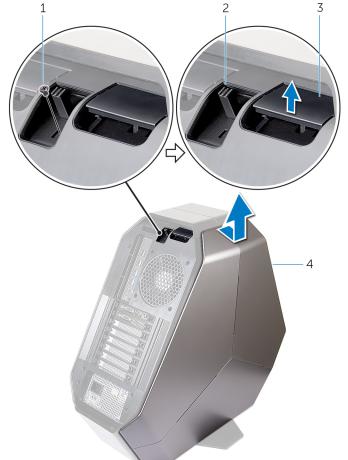
3Pull and lift the right side-panel away from the chassis.
1 |
screw |
2 |
security-cable slot latch |
3 |
release panel |
4 |
right side-panel |
4Repeat the procedure from step 2 to step 3 on the left side-panel.
27

Replacing the Side Panels
WARNING: Before working inside your computer, read the safety information that shipped with your computer and follow the steps in Before Working Inside Your Computer.
After working inside your computer, follow the instructions in After Working Inside Your Computer. For more safety best practices, see the Regulatory Compliance home page at dell.com/regulatory_compliance.
Procedure
1Align the tabs on the right side-panel with the slots on the right side of the computer and snap the panel to lock it in place.
2Repeat step 1 to replace the left side-panel.
3Slide and hold the security-cable slot latch in the locked position.
4Replace the screw that secures the security-cable slot latch.
28

Removing the Battery
WARNING: Before working inside your computer, read the safety information that shipped with your computer and follow the steps in Before Working Inside Your Computer.
After working inside your computer, follow the instructions in After Working Inside Your Computer. For more safety best practices, see the Regulatory Compliance home page at dell.com/regulatory_compliance.
Prerequisites
Remove the right side-panel. See “Removing the Side Panels”.
29

Procedure
Slide and open the battery-case door and remove the batteries from the battery-case.
1 |
battery-case door |
2 AA batteries (2) |
30
Loading...