


 Loading...
Alienware 17 R4
Service Manual
Computer Model: Alienware 17 R4
Regulatory Model: P31E
Regulatory Type: P31E001
Notes, cautions, and warnings
NOTE: A NOTE indicates important information that helps you make better use of your product.
CAUTION: A CAUTION indicates either potential damage to hardware or loss of data and tells you how to avoid the problem.
WARNING: A WARNING indicates a potential for property damage, personal injury, or death.
Copyright © 2016 Dell Inc. or its subsidiaries. All rights reserved. Dell, EMC, and other trademarks are trademarks of Dell Inc. or its subsidiaries. Other trademarks may be trademarks of their respective owners.
2016 - 12
Rev. A01
Contents |
|
Before working inside your computer |
.........................11 |
Before you begin ............................................................................ |
11 |
Safety instructions............................................................................ |
11 |
Recommended tools........................................................................ |
12 |
Screw list........................................................................................ |
13 |
After working inside your computer.......................... |
15 |
Removing the base cover............................................. |
16 |
Procedure....................................................................................... |
16 |
Replacing the base cover............................................. |
19 |
Procedure....................................................................................... |
19 |
Removing the hard drive............................................. |
20 |
Prerequisites.................................................................................. |
20 |
Procedure...................................................................................... |
20 |
Replacing the hard drive............................................. |
23 |
Procedure...................................................................................... |
23 |
Post-requisites................................................................................ |
23 |
Removing the wireless card........................................ |
24 |
Prerequisites.................................................................................. |
24 |
Procedure...................................................................................... |
24 |
3
Replacing the wireless card........................................ |
26 |
Procedure...................................................................................... |
26 |
Post-requisites................................................................................ |
27 |
Removing the solid-state drive................................... |
28 |
Prerequisites................................................................................... |
28 |
Procedure...................................................................................... |
28 |
Replacing the solid-state drive................................... |
30 |
Procedure...................................................................................... |
30 |
Post-requisites................................................................................ |
31 |
Removing the memory modules.................................. |
32 |
Prerequisites................................................................................... |
32 |
Procedure...................................................................................... |
32 |
Replacing the memory modules.................................. |
34 |
Procedure...................................................................................... |
34 |
Post-requisites................................................................................ |
35 |
Removing the rear-I/O cover..................................... |
36 |
Prerequisites.................................................................................. |
36 |
Procedure...................................................................................... |
36 |
Replacing the rear-I/O cover..................................... |
38 |
Procedure...................................................................................... |
38 |
Post-requisites................................................................................ |
38 |
Removing the computer base...................................... |
39 |
Prerequisites.................................................................................. |
39 |
Procedure...................................................................................... |
39 |
4
Replacing the computer base...................................... |
43 |
Procedure...................................................................................... |
43 |
Post-requisites................................................................................ |
43 |
Removing the coin-cell battery................................... |
44 |
Prerequisites.................................................................................. |
44 |
Procedure...................................................................................... |
44 |
Replacing the coin-cell battery................................... |
46 |
Procedure...................................................................................... |
46 |
Post-requisites............................................................................... |
46 |
Removing the speakers............................................... |
47 |
Prerequisites................................................................................... |
47 |
Procedure...................................................................................... |
47 |
Replacing the speakers............................................... |
49 |
Procedure...................................................................................... |
49 |
Post-requisites............................................................................... |
49 |
Removing the I/O board............................................ |
50 |
Prerequisites.................................................................................. |
50 |
Procedure...................................................................................... |
50 |
Replacing the I/O board............................................. |
53 |
Procedure...................................................................................... |
53 |
Post-requisites................................................................................ |
53 |
Removing the subwoofer............................................ |
54 |
Prerequisites.................................................................................. |
54 |
Procedure...................................................................................... |
54 |
5
Replacing the subwoofer............................................ |
56 |
Procedure...................................................................................... |
56 |
Post-requisites............................................................................... |
56 |
Removing the system-board assembly....................... |
57 |
Prerequisites................................................................................... |
57 |
Procedure...................................................................................... |
57 |
Replacing the system board........................................ |
63 |
Procedure...................................................................................... |
63 |
Post-requisites............................................................................... |
64 |
Removing the heat-sink assembly.............................. |
65 |
Prerequisites.................................................................................. |
65 |
Procedure...................................................................................... |
65 |
Replacing the heat-sink assembly.............................. |
68 |
Procedure...................................................................................... |
68 |
Post-requisites................................................................................ |
68 |
Removing the power-adapter port............................. |
70 |
Prerequisites.................................................................................. |
70 |
Procedure...................................................................................... |
70 |
Replacing the power-adapter port............................. |
72 |
Procedure...................................................................................... |
72 |
Post-requisites................................................................................ |
72 |
Removing the power-button board............................ |
73 |
Prerequisites................................................................................... |
73 |
Procedure...................................................................................... |
73 |
6
Replacing the power-button board............................ |
75 |
Procedure...................................................................................... |
75 |
Post-requisites................................................................................ |
75 |
Removing the display assembly.................................. |
76 |
Prerequisites................................................................................... |
76 |
Procedure...................................................................................... |
76 |
Replacing the display assembly.................................. |
78 |
Procedure...................................................................................... |
78 |
Post-requisites................................................................................ |
78 |
Removing the battery.................................................. |
79 |
Prerequisites................................................................................... |
79 |
Procedure...................................................................................... |
79 |
Replacing the battery.................................................. |
81 |
Procedure....................................................................................... |
81 |
Post-requisites................................................................................ |
81 |
Removing the touch pad............................................. |
82 |
Prerequisites................................................................................... |
82 |
Procedure...................................................................................... |
82 |
Replacing the touch pad............................................. |
85 |
Procedure...................................................................................... |
85 |
Post-requisites................................................................................ |
85 |
Removing the keyboard.............................................. |
86 |
Prerequisites.................................................................................. |
86 |
Procedure...................................................................................... |
86 |
7
Replacing the keyboard.............................................. |
89 |
Procedure...................................................................................... |
89 |
Post-requisites................................................................................ |
89 |
Removing the palm rest.............................................. |
90 |
Prerequisites.................................................................................. |
90 |
Procedure....................................................................................... |
91 |
Replacing the palm rest............................................... |
92 |
Procedure...................................................................................... |
92 |
Post-requisites............................................................................... |
92 |
Removing the display bezel........................................ |
93 |
Prerequisites.................................................................................. |
93 |
Procedure...................................................................................... |
93 |
Replacing the display bezel........................................ |
96 |
Procedure...................................................................................... |
96 |
Post-requisites............................................................................... |
96 |
Removing the tobii eye-tracker module..................... |
97 |
Prerequisites................................................................................... |
97 |
Procedure...................................................................................... |
97 |
Replacing the tobii eye-tracker module..................... |
99 |
Procedure...................................................................................... |
99 |
Post-requisites............................................................................... |
99 |
Removing the logo board.......................................... |
100 |
Prerequisites................................................................................ |
100 |
Procedure.................................................................................... |
100 |
8
Replacing the logo board.......................................... |
103 |
Procedure.................................................................................... |
103 |
Post-requisites.............................................................................. |
103 |
Removing the display panel...................................... |
104 |
Prerequisites................................................................................ |
104 |
Procedure.................................................................................... |
104 |
Replacing the display panel...................................... |
107 |
Procedure.................................................................................... |
107 |
Post-requisites.............................................................................. |
107 |
Removing the camera................................................ |
108 |
Prerequisites................................................................................. |
108 |
Procedure.................................................................................... |
108 |
Replacing the camera................................................. |
110 |
Procedure..................................................................................... |
110 |
Post-requisites.............................................................................. |
110 |
Removing the display hinges..................................... |
111 |
Prerequisites.................................................................................. |
111 |
Procedure..................................................................................... |
112 |
Replacing the display hinges..................................... |
115 |
Procedure..................................................................................... |
115 |
Post-requisites.............................................................................. |
115 |
Removing the display back-cover and antenna |
|
assembly..................................................................... |
117 |
Prerequisites.................................................................................. |
117 |
Procedure..................................................................................... |
118 |
9
Replacing the display back-cover and antenna |
|
assembly..................................................................... |
120 |
Procedure.................................................................................... |
120 |
Post-requisites.............................................................................. |
120 |
BIOS overview........................................................... |
122 |
Entering the BIOS setup program.................................................. |
122 |
Timing key sequences.................................................................... |
122 |
System Setup Options................................................................... |
122 |
Clearing forgotten passwords........................................................ |
128 |
Clearing CMOS settings................................................................ |
128 |
Flashing the BIOS......................................................................... |
129 |
Boot menu.................................................................................... |
129 |
Boot menu enhancements............................................................. |
129 |
Diagnostics................................................................. |
130 |
Getting help and contacting Alienware................... |
132 |
Self-help resources....................................................................... |
132 |
Contacting Alienware................................................................... |
133 |
10
Before working inside your computer
NOTE: The images in this document may differ from your computer depending on the configuration you ordered.
Before you begin
1Save and close all open files and exit all open applications.
2Shut down your computer. Click Start →  Power → Shut down.
NOTE: If you are using a different operating system, see the documentation of your operating system for shut-down instructions.
3Disconnect your computer and all attached devices from their electrical outlets.
4Disconnect all attached network devices and peripherals, such as keyboard, mouse, and monitor from your computer.
5 Remove any media card and optical disc from your computer, if applicable.
6Close the display and turn the computer over.
Safety instructions
Use the following safety guidelines to protect your computer from potential damage and ensure your personal safety.
WARNING: Before working inside your computer, read the safety information that shipped with your computer. For more safety best practices, see the Regulatory Compliance home page at www.dell.com/ regulatory_compliance.
WARNING: Disconnect all power sources before opening the computer cover or panels. After you finish working inside the computer, replace all covers, panels, and screws before connecting to the electrical outlet.
11

CAUTION: To avoid damaging the computer, ensure that the work surface is flat and clean.
CAUTION: To avoid damaging the components and cards, handle them by their edges, and avoid touching pins and contacts.
CAUTION: You should only perform troubleshooting and repairs as authorized or directed by the Dell technical assistance team. Damage due to servicing that is not authorized by Dell is not covered by your warranty. See the safety instructions that shipped with the product or at www.dell.com/regulatory_compliance.
CAUTION: Before touching anything inside your computer, ground yourself by touching an unpainted metal surface, such as the metal at the back of the computer. While you work, periodically touch an unpainted metal surface to dissipate static electricity, which could harm internal components.
CAUTION: When you disconnect a cable, pull on its connector or on its pull tab, not on the cable itself. Some cables have connectors with locking tabs or thumb-screws that you must disengage before disconnecting the cable. When disconnecting cables, keep them evenly aligned to avoid bending any connector pins. When connecting cables, ensure that the ports and connectors are correctly oriented and aligned.
CAUTION: Press and eject any installed card from the media-card reader.
Recommended tools
The procedures in this document may require the following tools:
•Phillips screwdriver
•Plastic scribe
12
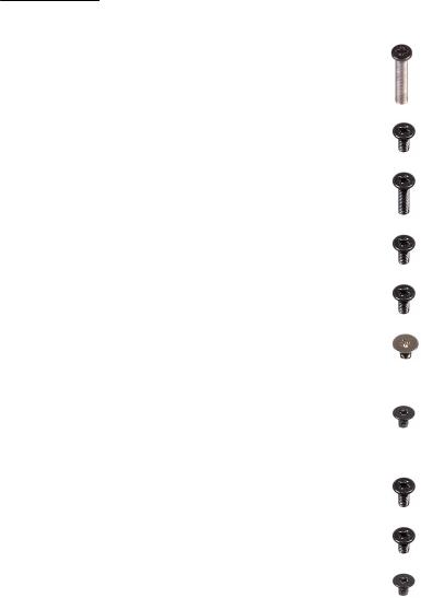
Screw list
Table 1. Screw list
Component |
Secured to |
Screw type |
Quantity |
Screw |
|
|
|
|
image |
Base cover |
Palm-rest |
M2.5x13 |
6 |
|
|
assembly |
|
|
|
Battery |
Palm-rest |
M2.5x5 |
4 |
|
|
assembly |
|
|
|
Computer base |
Palm-rest |
M2.5x8 |
14 |
|
|
assembly |
|
|
|
Computer base |
Palm-rest |
M2.5x5 |
2 |
|
|
assembly |
|
|
|
Display |
Palm-rest |
M2.5x5 |
6 |
|
assembly |
assembly |
|
|
|
Display hinges |
Display back- |
M2.5x3 |
12 |
|
|
cover and |
|
|
|
|
antenna |
|
|
|
|
assembly |
|
|
|
Display panel |
Display back- |
M2x3 |
4 |
|
|
cover and |
|
|
|
|
antenna |
|
|
|
|
assembly |
|
|
|
Hard-drive |
Computer base |
M2.5x5 |
4 |
|
assembly |
|
|
|
|
Hard-drive |
Hard-drive |
M3x3 |
4 |
|
bracket |
assembly |
|
|
|
Heat-sink |
System board |
M2x3 |
7 |
|
assembly |
|
|
|
|
13
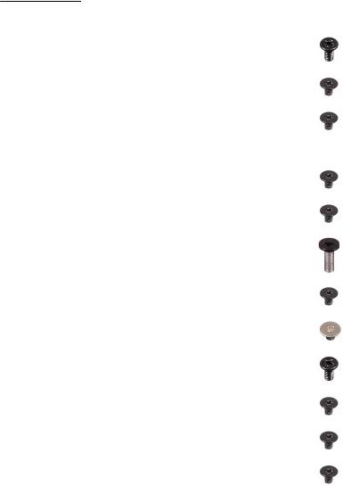
Component |
Secured to |
Screw type |
Quantity |
Screw |
|
|
|
|
image |
I/O board |
Palm-rest |
M2.5x5 |
2 |
|
|
assembly |
|
|
|
Keyboard |
Palm-rest |
M2x3 |
17 |
|
bracket |
assembly |
|
|
|
Logo board |
Display back- |
M2x3 |
2 |
|
|
cover and |
|
|
|
|
antenna |
|
|
|
|
assembly |
|
|
|
Power-adapter |
Palm-rest |
M2x3 |
1 |
|
port bracket |
assembly |
|
|
|
Power-button |
Palm-rest |
M2x3 |
2 |
|
board |
assembly |
|
|
|
Rear-I/O cover |
Computer base |
M2.5x7 |
2 |
|
Solid-state |
Computer base |
M2x3 |
1 |
|
drive |
|
|
|
|
Subwoofer |
Palm-rest |
M2x2 |
2 |
|
|
assembly |
|
|
|
System-board |
Palm-rest |
M2.5x5 |
7 |
|
assembly |
assembly |
|
|
|
Touch-pad |
Palm-rest |
M2x3 |
5 |
|
bracket |
assembly |
|
|
|
Tron-light |
Computer base |
M2x3 |
2 |
|
holder |
|
|
|
|
Wireless-card |
Computer base |
M2x3 |
1 |
|
bracket |
|
|
|
|
14

After working inside your computer
CAUTION: Leaving stray or loose screws inside your computer may severely damage your computer.
1Replace all screws and ensure that no stray screws remain inside your computer.
2Connect any external devices, peripherals, or cables you removed before working on your computer.
3Replace any media cards, discs, or any other parts that you removed before working on your computer.
4 Connect your computer and all attached devices to their electrical outlets.
5Turn on your computer.
15

Removing the base cover
WARNING: Before working inside your computer, read the safety information that shipped with your computer and follow the steps in Before working inside your computer. After working inside your computer, follow the instructions in After working inside your computer. For more safety best practices, see the Regulatory Compliance home page at www.dell.com/regulatory_compliance.
Procedure
1Remove the six screws (M2.5x13) that secure the base cover to the computer base.
2Loosen the captive screw that secures the base cover to the computer base.
16
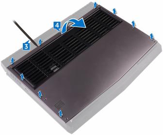
3Using a plastic scribe, gently pry the base cover to release the tabs on the base cover from the slots on the computer base.
4Lift the base cover off the computer base.
17

5Disconnect the battery cable from the system board.
6Press and hold the power button for five seconds to ground the system board.
18

Replacing the base cover
WARNING: Before working inside your computer, read the safety information that shipped with your computer and follow the steps in Before working inside your computer. After working inside your computer, follow the instructions in After working inside your computer. For more safety best practices, see the Regulatory Compliance home page at www.dell.com/regulatory_compliance.
Procedure
1Connect the battery cable to the system board.
2Slide the tabs on the base cover into the slots on the computer base and snap the base cover into place.
3Tighten the captive screw that secures the base cover to the computer base.
4Replace the six screws (M2.5x13) that secure the base cover to the computer base.
19

Removing the hard drive
WARNING: Before working inside your computer, read the safety information that shipped with your computer and follow the steps in Before working inside your computer. After working inside your computer, follow the instructions in After working inside your computer. For more safety best practices, see the Regulatory Compliance home page at www.dell.com/regulatory_compliance.
CAUTION: Hard drives are fragile. Exercise care when handling the hard drive.
CAUTION: To avoid data loss, do not remove the hard drive while the computer is in sleep or on state.
Prerequisites
Remove the base cover.
Procedure
1Using the pull-tab, disconnect the hard-drive cable from the system board.
2Remove the hard-drive cable from the routing guides on the computer base.
3Remove the four screws (M2.5x5) that secure the hard-drive assembly to the computer base.
20

4Lift the hard-drive assembly along with its cable off the computer base.
5Remove the four screws (M3x3) that secure the hard-drive bracket to the hard-drive assembly.
6Lift the hard-drive bracket off the hard-drive assembly.
21
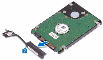
7Disconnect the interposer from the hard drive.
22

Replacing the hard drive
WARNING: Before working inside your computer, read the safety information that shipped with your computer and follow the steps in Before working inside your computer. After working inside your computer, follow the instructions in After working inside your computer. For more safety best practices, see the Regulatory Compliance home page at www.dell.com/regulatory_compliance.
CAUTION: Hard drives are fragile. Exercise care when handling the hard drive.
Procedure
1Connect the interposer to the hard drive.
2Align the screw holes on the hard-drive bracket with the screw holes on the hard-drive assembly.
3Replace the four screws (M3x3) that secure the hard-drive bracket to the hard-drive assembly.
4Align the screw holes on the hard-drive assembly with the screw holes on the computer base.
5Replace the four screws (M2.5x5) that secure the hard-drive assembly to the computer base.
6 Route the hard-drive cable through the routing guides on the computer base.
7Connect the hard-drive cable to the system board.
Post-requisites
Replace the base cover.
23

Removing the wireless card
WARNING: Before working inside your computer, read the safety information that shipped with your computer and follow the steps in Before working inside your computer. After working inside your computer, follow the instructions in After working inside your computer. For more safety best practices, see the Regulatory Compliance home page at www.dell.com/regulatory_compliance.
Prerequisites
Remove the base cover.
Procedure
1Remove the screw (M2x3) that secures the wireless-card bracket to the computer base.
2 Slide and remove the wireless-card bracket from the wireless card.
3Disconnect the antenna cables from the wireless card.
24
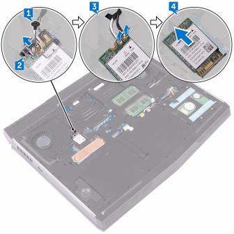
4Slide the wireless card out of the wireless-card slot.
25

Replacing the wireless card
WARNING: Before working inside your computer, read the safety information that shipped with your computer and follow the steps in Before working inside your computer. After working inside your computer, follow the instructions in After working inside your computer. For more safety best practices, see the Regulatory Compliance home page at www.dell.com/regulatory_compliance.
Procedure
CAUTION: To avoid damaging the wireless card, do not place any cables under it.
1 Align the notch on the wireless card with the tab on the wireless-card slot.
2Slide the wireless card at an angle into the wireless-card slot.
3Connect the antenna cables to the wireless card.
The following table provides the antenna-cable color scheme for the wireless card supported by your computer.
Table 2. Antenna-cable color scheme
Connectors on the wireless card |
Antenna cable color |
|
|
Auxiliary (black triangle) |
Black |
Main (white triangle) |
White |
4Slide the wireless card bracket on to the wireless card, and align the screw hole on the wireless-card bracket with the screw hole on the wireless card and the computer base.
26
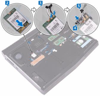
5Press the other end of the wireless card and replace the screw (M2x3) that secures the wireless-card bracket to the computer base.
Post-requisites
Replace the base cover.
27

Removing the solid-state drive
WARNING: Before working inside your computer, read the safety information that shipped with your computer and follow the steps in Before working inside your computer. After working inside your computer, follow the instructions in After working inside your computer. For more safety best practices, see the Regulatory Compliance home page at www.dell.com/regulatory_compliance.
CAUTION: Solid-state drives are fragile. Exercise care when handling the solid-state drive.
CAUTION: To avoid data loss, do not remove the solid-state drive while the computer is in sleep or on state.
Prerequisites
Remove the base cover.
Procedure
1Remove the screw (M2x3) that secures the solid-state drive shield and solidstate drive to the computer base.
2Peel off the solid-state drive shield from the solid-state drive.
NOTE: Solid-state drive shield is applicable to computers that are shipped with 1 TB solid-state drive.
28
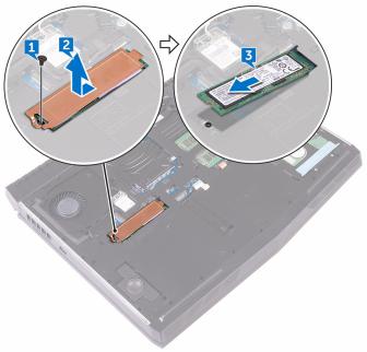
3Slide and remove the solid-state drive from the solid-state drive slot.
29
Replacing the solid-state drive
WARNING: Before working inside your computer, read the safety information that shipped with your computer and follow the steps in Before working inside your computer. After working inside your computer, follow the instructions in After working inside your computer. For more safety best practices, see the Regulatory Compliance home page at www.dell.com/regulatory_compliance.
CAUTION: Solid-state drives are fragile. Exercise care when handling the solid-state drive.
Procedure
1Align the notch on the solid-state drive with the tab on the solid-state drive slot.
2Slide the solid-state drive into the solid-state drive slot.
3Slide and adhere the solid-state drive shield on the solid-state drive.
4Align the screw hole on the solid-state drive and solid-state drive shield with the screw hole on the computer base.
30
Loading...